EP0796991A1 - Druckregelventil mit Anschlussverbindung - Google Patents
Druckregelventil mit Anschlussverbindung Download PDFInfo
- Publication number
- EP0796991A1 EP0796991A1 EP96118678A EP96118678A EP0796991A1 EP 0796991 A1 EP0796991 A1 EP 0796991A1 EP 96118678 A EP96118678 A EP 96118678A EP 96118678 A EP96118678 A EP 96118678A EP 0796991 A1 EP0796991 A1 EP 0796991A1
- Authority
- EP
- European Patent Office
- Prior art keywords
- coupling part
- valve
- pressure control
- connection
- control valve
- Prior art date
- Legal status (The legal status is an assumption and is not a legal conclusion. Google has not performed a legal analysis and makes no representation as to the accuracy of the status listed.)
- Granted
Links
- 230000001105 regulatory effect Effects 0.000 title abstract description 8
- 230000008878 coupling Effects 0.000 claims abstract description 53
- 238000010168 coupling process Methods 0.000 claims abstract description 53
- 238000005859 coupling reaction Methods 0.000 claims abstract description 53
- 239000012530 fluid Substances 0.000 claims abstract description 26
- 239000012528 membrane Substances 0.000 claims abstract description 9
- 239000000446 fuel Substances 0.000 claims description 11
- 238000007789 sealing Methods 0.000 claims description 9
- 238000002485 combustion reaction Methods 0.000 claims description 5
- 210000000078 claw Anatomy 0.000 description 19
- 238000003780 insertion Methods 0.000 description 5
- 230000037431 insertion Effects 0.000 description 5
- 238000004519 manufacturing process Methods 0.000 description 3
- 238000005452 bending Methods 0.000 description 2
- 230000007704 transition Effects 0.000 description 2
- 230000004323 axial length Effects 0.000 description 1
- 230000005540 biological transmission Effects 0.000 description 1
- 238000011161 development Methods 0.000 description 1
- 230000018109 developmental process Effects 0.000 description 1
- 230000000694 effects Effects 0.000 description 1
- 229920001971 elastomer Polymers 0.000 description 1
- 239000000806 elastomer Substances 0.000 description 1
- 230000002349 favourable effect Effects 0.000 description 1
- 239000002828 fuel tank Substances 0.000 description 1
- 239000000463 material Substances 0.000 description 1
Images

Classifications
-
- F—MECHANICAL ENGINEERING; LIGHTING; HEATING; WEAPONS; BLASTING
- F02—COMBUSTION ENGINES; HOT-GAS OR COMBUSTION-PRODUCT ENGINE PLANTS
- F02M—SUPPLYING COMBUSTION ENGINES IN GENERAL WITH COMBUSTIBLE MIXTURES OR CONSTITUENTS THEREOF
- F02M69/00—Low-pressure fuel-injection apparatus ; Apparatus with both continuous and intermittent injection; Apparatus injecting different types of fuel
- F02M69/46—Details, component parts or accessories not provided for in, or of interest apart from, the apparatus covered by groups F02M69/02 - F02M69/44
- F02M69/54—Arrangement of fuel pressure regulators
-
- F—MECHANICAL ENGINEERING; LIGHTING; HEATING; WEAPONS; BLASTING
- F16—ENGINEERING ELEMENTS AND UNITS; GENERAL MEASURES FOR PRODUCING AND MAINTAINING EFFECTIVE FUNCTIONING OF MACHINES OR INSTALLATIONS; THERMAL INSULATION IN GENERAL
- F16L—PIPES; JOINTS OR FITTINGS FOR PIPES; SUPPORTS FOR PIPES, CABLES OR PROTECTIVE TUBING; MEANS FOR THERMAL INSULATION IN GENERAL
- F16L37/00—Couplings of the quick-acting type
- F16L37/08—Couplings of the quick-acting type in which the connection between abutting or axially overlapping ends is maintained by locking members
- F16L37/084—Couplings of the quick-acting type in which the connection between abutting or axially overlapping ends is maintained by locking members combined with automatic locking
- F16L37/088—Couplings of the quick-acting type in which the connection between abutting or axially overlapping ends is maintained by locking members combined with automatic locking by means of a split elastic ring
-
- F—MECHANICAL ENGINEERING; LIGHTING; HEATING; WEAPONS; BLASTING
- F16—ENGINEERING ELEMENTS AND UNITS; GENERAL MEASURES FOR PRODUCING AND MAINTAINING EFFECTIVE FUNCTIONING OF MACHINES OR INSTALLATIONS; THERMAL INSULATION IN GENERAL
- F16L—PIPES; JOINTS OR FITTINGS FOR PIPES; SUPPORTS FOR PIPES, CABLES OR PROTECTIVE TUBING; MEANS FOR THERMAL INSULATION IN GENERAL
- F16L37/00—Couplings of the quick-acting type
- F16L37/08—Couplings of the quick-acting type in which the connection between abutting or axially overlapping ends is maintained by locking members
- F16L37/084—Couplings of the quick-acting type in which the connection between abutting or axially overlapping ends is maintained by locking members combined with automatic locking
- F16L37/098—Couplings of the quick-acting type in which the connection between abutting or axially overlapping ends is maintained by locking members combined with automatic locking by means of flexible hooks
-
- G—PHYSICS
- G05—CONTROLLING; REGULATING
- G05D—SYSTEMS FOR CONTROLLING OR REGULATING NON-ELECTRIC VARIABLES
- G05D16/00—Control of fluid pressure
- G05D16/04—Control of fluid pressure without auxiliary power
- G05D16/06—Control of fluid pressure without auxiliary power the sensing element being a flexible membrane, yielding to pressure, e.g. diaphragm, bellows, capsule
- G05D16/063—Control of fluid pressure without auxiliary power the sensing element being a flexible membrane, yielding to pressure, e.g. diaphragm, bellows, capsule the sensing element being a membrane
- G05D16/0644—Control of fluid pressure without auxiliary power the sensing element being a flexible membrane, yielding to pressure, e.g. diaphragm, bellows, capsule the sensing element being a membrane the membrane acting directly on the obturator
- G05D16/0655—Control of fluid pressure without auxiliary power the sensing element being a flexible membrane, yielding to pressure, e.g. diaphragm, bellows, capsule the sensing element being a membrane the membrane acting directly on the obturator using one spring-loaded membrane
Definitions
- the invention relates to a pressure control valve according to the preamble of claim 1.
- a pressure control valve is usually used to regulate the pressure in a fuel supply system of an internal combustion engine.
- the pressure control valve is located on the pressure side of the fuel pump. The excess amount of fuel not required by the internal combustion engine is returned to a fuel reservoir via the pressure control valve.
- the pressure control valve regulates the pressure on the pressure side of the fuel pump.
- Known pressure control valves usually have an inlet connection and a return connection for the fuel.
- the European patent application EP-A-0 392 313 and the American patent US 4,928,729 show such a pressure control valve.
- a further line can be connected to the return connection.
- the outgoing lines have different diameters and / or the shape of the
- the return connection for connecting the further lines must be different depending on the vehicle type and / or depending on the vehicle type, the return connection of the pressure control valve must be straight or angled, whereby the required angle can vary depending on the vehicle type. This results in a large number of embodiments of the pressure control valve.
- the large number of embodiments leads to expensive storage of different pressure regulating valves and leads to high manufacturing costs because only a relatively small number of pieces can be produced from each embodiment.
- the pressure control valve according to the invention with a connection with the characterizing features of claim 1 has the advantage that regardless of the type of line to be connected to the pressure control valve, a uniformly designed pressure control valve can be manufactured and stored. This results in high quantities per production lot, which has a favorable effect on the manufacturing costs of the pressure control valve.
- the snap connection which ensures that an area of the pressure control valve is in engagement with the coupling part in the assembled state, advantageously ensures a secure connection between the pressure control valve and the coupling part.
- the snap connection ensures that the coupling part can be connected to the pressure control valve without great effort.
- the sealing ring advantageously ensures a reliable seal between the coupling part and the pressure control valve.
- the regulator nozzle with the plug opening can advantageously be essentially completely integrated into the valve housing of the pressure regulating valve, which has the advantage that the overall dimensions of the pressure regulating valve are small and that the pressure regulating valve can be produced inexpensively, and furthermore the regulator nozzle with the plug opening is installed at a protected location .
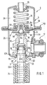
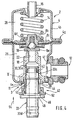
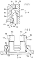
- FIGS. 1 and 4 show different exemplary embodiments and FIGS. 2, 3, 5 and 6 exemplify some details of the exemplary embodiments.
- the pressure control valve according to the invention with connection connection serves to control a pressure of a fluid, preferably fuel, in a fluid space.
- the pressure regulating valve can preferably be used in internal combustion engines in which a pressure of the fuel is to be regulated in the fuel supply system.
- FIG. 1 shows, based on a first exemplary embodiment, a cross section through a particularly advantageous pressure control valve 2, which has been selected for the description and is particularly advantageous, with a connection 3.
- the pressure control valve 2 comprises a valve housing 4, a membrane 6, a closing body 8, a regulator nozzle 10, a first fluid connection 11, a second fluid connection 12, a closing spring 14 and a connection 16.
- the valve housing 4 is composed of a lower housing part 4a and an upper housing part 4b.
- the membrane 6 is clamped between the lower housing part 4a and the upper housing part 4b along its circumference.
- the closing body 8 comprises, for example, a ball 8a, a holding element 8b, a spring plate 8c, a spring guide 8d, a closing disk 8e and a retaining disk 8f.
- the membrane 6 has a central recess and is clamped on the circumference of this recess in the closing body 8 between the holding element 8b and the spring plate 8c.
- the closing disc 8e is firmly connected to the ball 8a.
- the holding disc 8f holds the ball 8a on the holding element 8b of the closing body 8.
- the regulator nozzle 10 has an inner end facing the closing body 8 with a first end face, on which there is a valve seat 18, and an outer end leading away from the valve body 4, facing away from the closing body 8, with a second end face, which is subsequently called the outer end face 20 of the Regulator nozzle 10 is called.
- a connection opening 22 runs through the regulator nozzle 10. The connection opening 22 leads from the valve seat 18 to the outer end face 20.
- the regulator nozzle 10 is made in one piece. However, it should be mentioned that the regulator nozzle 10 also consists of two, can consist of firmly joined parts by means of a press fit.
- the second fluid connection 12 serves as an inlet connection.
- a pump not shown, for example a fuel pump
- a line not shown, leads to the fluid connection 12.
- a fluid line 24 leads, for example, to a storage container or fuel tank, not shown. In FIG. 1, only the end of the fluid line 24 facing the pressure control valve 2 is shown.
- the membrane 6 separates a fluid chamber 26 from a valve chamber 28.
- the valve chamber 28 is connected via the connection 16 via a line, not shown, for example to an intake pipe of the internal combustion engine, not shown.
- the fluid connection 12 serves as an inlet connection and the fluid connection 11 serves as a return connection.
- the pressure in the valve chamber 28 and the force of the closing spring 14 result in a closing force.
- the closing body 8 lifts against the closing force from the valve seat 18, and the fluid can pass from the fluid connection 12 through the fluid space 26, through one between the closing disc 8e and the valve seat 18 forming gap, flow through the connection opening 22, via the fluid connection 11 into the fluid line 24.
- the regulator nozzle 10 protrudes through the housing recess 4e.
- the regulator nozzle 10 is installed in the housing recess 4e in such a way that the clearly predominant part of the regulator nozzle 10 is located within the valve housing 4. Essentially, only the outer end face 20 projects out of the valve housing 4 from the regulator nozzle 10.
- the regulator nozzle 10 is tightly and firmly connected to the valve housing 4 in the region of its outer end face 20 on the outer circumference. This connection between the regulator nozzle 10 and the valve housing 4 can take place, for example, by flanging.
- the lower housing part 4a is firmly and tightly connected to the upper housing part 4b via a flange connection 4g.
- the flange connection 4g is designed such that the membrane 6 is also held on its outer circumference in the flange connection 4g.
- the lower housing part 4a is dimensioned in the axial direction in such a way that there is sufficient space between the second fluid connection 12 and the flange connection 4g for the tool for processing the flange connection 4g. Because of the space required between the flare connection 4g and the fluid connection 12, the lower housing part 4a has to be dimensioned sufficiently long, the regulator nozzle 10 can be essentially completely integrated into the valve housing 4 without requiring additional space.
- a plug opening 30 is provided in the regulator nozzle 10.
- the plug opening 30 runs in continuation to the connection opening 22.
- a coupling part 33 designed as a plug is inserted into the plug opening 30.
- the connector 3 essentially includes the plug opening 30 provided on the valve housing 4 and the coupling part 33 provided on the fluid line 24
- Coupling part 33 has a through bore 33d, which is shown in dashed lines and connects the connection opening 22 to the fluid line 24.
- a snap connection 40 is provided to hold the coupling part 33 on the valve housing 4 of the pressure control valve 2.
- the snap connection 40 essentially consists of a housing stop 40g belonging to the valve housing 4 and a plug stop 40s belonging to the coupling part 33.
- the snap connection 40 also includes a mounting bevel 40m (FIG. 3) and a resilient ring 40r with a slot 40u (FIG. 2).
- a sealing ring 42 serves to seal between the outer periphery of the coupling part 33 and the plug opening 30 of the regulator nozzle 10.
- regulator nozzle 10 and part of the coupling part 33 are shown again in individual figures with a changed scale as a single part.
- FIG. 2 essentially shows the regulator nozzle 10.
- the plug opening 30 for receiving the coupling part 33 has a cylindrical, stepped inner surface with a smaller diameter 30a, a larger diameter 30b and an insertion bevel 30e (FIG. 2).
- a recess 30f is provided in the region of the larger diameter 30b of the plug opening 30.
- the resilient ring 40r is located in the recess 30f.
- the resilient ring 40r is dimensioned so that it is held in the recess 30f.
- the resilient ring 40r is circumferential, but interrupted at one point by the slot 40u.
- the resilient ring 40r has a transverse side facing away from the outer end face 20.
- the housing stop 40g is located on this transverse side.
- FIG. 3 shows a section of the coupling part 33.
- the coupling part 33 has a cylindrical, stepped outer surface with a smaller diameter 33a, a larger diameter 33b and an insertion bevel 33e.
- a mounting slope 40m At the transition between the smaller diameter 33a and the larger diameter 33b, there is a mounting slope 40m.
- the mounting slope 40m is inclined approximately 45 degrees with respect to the longitudinal axis of the coupling part 33.
- the diameter 33c is dimensionally the same as the diameter 33a.
- the plug stop 40s is located on the coupling part 33.
- the plug stop 40s runs at right angles to the longitudinal direction of the coupling part 33.
- the sealing ring 42 is held on the coupling part 33 in the region of the smaller diameter 33a.
- a sealing ring recess 42a is provided on the outer circumference of the coupling part 33 in the region of the smaller diameter 33a.
- the resilient ring 40r When the coupling part 33 is inserted into the plug opening 30 provided in the regulator nozzle 10, as soon as the mounting bevel 40m meets the resilient ring 40r, the resilient ring 40r is expanded radially until the larger diameter 33b of the coupling part 33 is pushed through the resilient ring 40r.
- the resilient radial movement of the resilient ring 40r is made possible by the slot 40u and the fact that the diameter of the recess 30f holding the resilient ring 40r is larger than the outer diameter of the resilient ring 40r.
- the coupling part 33 is held in the plug opening 30 in that the connector stop 40s provided on the coupling part 33 is held by the housing stop 40g provided on the resilient ring 40r.
- the resilient ring 40r in turn is held by the recess 30f in relation to the valve housing 4.
- the resilient ring 40r can alternatively also be arranged in a recess provided on the outer circumference of the coupling part 33.
- the sealing ring recess 42a for holding the sealing ring 42 can alternatively also be provided in the regulator nozzle 10 as an interruption of the smaller diameter 30a of the plug opening 30.
- the snap connection 40 is designed so that an easy connection of the coupling part 33 to the valve housing 4 is possible and that the coupling part 33 is securely coupled to the valve housing 4. A simple disassembly of the coupling part 33 from the valve housing 4 is not provided in the embodiment according to FIG. 1.
- FIG. 4 shows a further, particularly selected, advantageous exemplary embodiment.
- a securing collar 44, a shoulder 46 and a projection 48 on the coupling part 33 There is a securing collar 44, a shoulder 46 and a projection 48 on the coupling part 33.
- a circumferential retaining element 50 is installed between the securing collar 44 and the shoulder 46.
- a disassembly aid 52 is provided.
- a circumferential, radially inwardly projecting projection 4v is provided on the valve housing 4 or on the regulator nozzle 10 in the region of the outer end face 20.
- the plug opening 30, the projection 4v, the housing stop 40g (FIG. 5), the coupling part 33, the holding element 50, the plug stop 40s (FIG. 5), and the removal aid 52 belong to the connection connection 3rd
- FIG. 5 shows a detail from FIG. 4.
- the area around the securing collar 44, the projection 4v and the area of the holding element 50 which is in engagement with the projection 4v is again shown in FIG. 5 with a changed scale for the sake of clarity reproduced.
- the area shown in FIG. 5 is indicated in FIG. 4 by a circle denoted by V.
- FIG. 6 again shows the holding element 50 and the dismantling aid 52 with a changed scale, the remaining components not being shown in FIG. 6 for the sake of clarity.
- FIGS. 1-10 For better understanding of the following description, an arrow 54 pointing in the same direction in all figures is shown in FIGS.
- the holding element 50 has a front area 50a and a rear area 50b (FIG. 6).
- the front area 50a is slotted in the longitudinal direction, so that there are several, for example four, claws 50c on the holding element 50.
- the holding claws 50c are circumferentially connected to one another.
- the front area 50a there are on the holding claws 50c radially outward projections on which the plug stop 40s is located.
- FIG. 6 shows the holding claws 50c in the inwardly pressed position with dashed lines. If the holding claws 50c, as shown in dashed lines in FIG. 6, are pressed inwards, then the plug stop 40s of the holding element 50 is disengaged from the housing stop 40g of the valve housing 4 (FIG. 5).
- the coupling part 33 together with the holding element 50 can be easily removed from the plug opening 30 (FIG. 4) against the arrow 54.
- the projection 48 is provided on the coupling part 33. With the aid of the projection 48, the holding claws 50c can be pressed radially inward by simply axially pressing the disassembly aid 52 and the projection 48 against one another.
- the dismantling aid 52 is pressed axially against the projection 48, the rear region 50b is supported of the holding element 50 at the end on the shoulder 46, which enables the force transmission between the two bevels 50d and 52d (FIG. 6).
- the securing collar 44 is provided as an additional measure, so that the coupling part 33 cannot inadvertently slip out of the plug-in opening 30 in the assembled state.
- a safety stop 44s on the safety collar 44 and a safety stop 50s (FIG. 5) running around with interruptions is provided on the front area 50a of the holding element 50.
- the safety stops 44s, 50s are inclined approximately 45 ° with respect to the axial direction.
- the coupling part 33 is pressed or pulled against arrow 54, the securing stop 44s on the coupling part 33 presses on the securing stop 50s of the holding element 50 and provides a force acting radially outward on the holding claws 50c.
- the holding claws 50c are pressed against the housing-side projection 4v, and it is ensured that the plug stop 40s remains in engagement with the housing stop 40g. If the force on the coupling part 33 increases, in the opposite direction of the arrow 54, then the force also increases, which serves to secure the engagement of the plug stop 40s relative to the housing stop 40g.
- the insertion bevels 4h and 50h are matched to one another in such a way that when the coupling part 33 is inserted in the direction of arrow 54 into the plug opening 30, the holding claws 50c of the holding element 50 are pressed elastically radially inward until the plug stop 40s provided on the holding claws 50c snaps over the projection 4v is and the holding claws 50c have come into active engagement with the housing stop 40g because of the elastically radially outward bias.
- the axial length of the holding element 50, which is held between the securing collar 44 and the shoulder 46, is dimensioned such that the holding element 50 has axial play between the securing collar 44 and the shoulder 46. Because of this axial play, when the coupling part 33 is inserted into the plug opening 30, the securing stop 44s (FIG. 5) lifts off the securing stop 50s, so that the radially inward movement of the holding claws 50c, which is elastic in the radial direction, is not hindered during assembly.
- the coupling part 33 In the assembled state, if the coupling part 33 is loaded against arrow 54, for example by the hydraulic pressure in the connection opening 22 or by a mechanical force, then the holding claws 50c are supported on the one hand on the housing stop 40g of the valve housing 4 and on the other hand on that provided on the coupling part 33 Fuse stop from 44s.
- the tension between the housing stop 40g, the holding claws 50c and the securing stop 44s can be released by slightly moving the coupling part 33 in the direction of arrow 54 and radially by simultaneously slightly bending the holding claws 50c the coupling part 33 can be removed inwardly from the valve housing 4 without great effort.
- the proposed disassembly aid 52 facilitates the radial bending of the holding claws 50c during the disassembly.
- the snap connection 40 essentially comprises the housing stop 40g assigned to the valve housing 4 (FIG. 5) and the holding element 50 supported on the securing collar 44 with the plug stop 40s assigned to the coupling part 33 (FIG. 5).
- the snap connection 40 is designed such that an easy connection of the coupling part 33 to the valve housing 4 is possible, the coupling part 33 is securely coupled to the valve housing 4 and, in addition, a simple disassembly of the coupling part 33 from the valve housing 4 is nevertheless possible.
Landscapes
- Engineering & Computer Science (AREA)
- General Engineering & Computer Science (AREA)
- Mechanical Engineering (AREA)
- Chemical & Material Sciences (AREA)
- Combustion & Propulsion (AREA)
- Physics & Mathematics (AREA)
- Fluid Mechanics (AREA)
- General Physics & Mathematics (AREA)
- Automation & Control Theory (AREA)
- Safety Valves (AREA)
- Fuel-Injection Apparatus (AREA)
- Control Of Fluid Pressure (AREA)
- Valve Housings (AREA)
Abstract
Description
- Die Erfindung geht aus von einem Druckregelventil nach der Gattung des Anspruchs 1.
- Zum Regeln des Drucks in einer Kraftstoffversorgungsanlage einer Brennkraftmaschine wird üblicherweise ein Druckregelventil verwendet. Das Druckregelventil befindet sich auf der Druckseite der Kraftstoffpumpe. Die von der Brennkraftmaschine nicht benötigte überschüssige Menge des Kraftstoffs wird über das Druckregelventil zu einem Kraftstoffvorratsbehälter zurückgeleitet. Dabei regelt das Druckregelventil den Druck auf der Druckseite der Kraftstoffpumpe.
- Bekannte Druckregelventile haben üblicherweise einen Zulaufanschluß und einen Rücklaufanschluß für den Kraftstoff. Die europäische Offenlegungsschrift EP-A-0 392 313 bzw. die amerikanische Patentschrift US 4,928,729 zeigen ein derartiges Druckregelventil. Bei diesem bekannten Druckregelventil kann an den Rücklaufanschluß eine weiterführende Leitung angeschlossen werden. Je nach Fahrzeugtyp haben die weiterführenden Leitungen unterschiedliche Durchmesser und/oder die Form des Rücklaufanschlusses zum Anschließen der weiterführenden Leitungen muß je nach Fahrzeugtyp unterschiedlich sein und/oder je nach Fahrzeugtyp muß der Rücklaufanschluß des Druckregelventils gerade oder abgewinkelt sein, wobei der erforderliche Winkel je nach Fahrzeugtyp unterschiedlich sein kann. Dadurch ergibt sich eine Vielzahl von Ausführungsformen des Druckregelventils. Die Vielzahl der Ausführungsformen führt zu einer kostspieligen Lagerhaltung unterschiedlicher Druckregelventile und führt zu hohen Herstellkosten, weil von jeder Ausführungsform nur eine relativ kleine Stückzahl gefertigt werden kann.
- Das erfindungsgemäße Druckregelventil mit Anschlußverbindung mit den kennzeichnenden Merkmalen des Anspruchs 1 hat demgegenüber den Vorteil, daß unabhängig von der Art der an das Druckregelventil anzuschließenden Leitung ein einheitlich ausgeführtes Druckregelventil hergestellt und bevorratet werden kann. Dadurch ergeben sich hohe Stückzahlen je Fertigungslos, was sich günstig auf die Herstellkosten des Druckregelventils auswirkt.
- Durch die in den Unteransprüchen aufgeführten Maßnahmen sind vorteilhafte Weiterbildungen und Verbesserungen des im Hauptanspruch angegebenen Druckregelventils möglich.
- Die Schnappverbindung, die dafür sorgt, daß im montierten Zustand ein Bereich des Druckregelventils in Eingriff mit dem Kupplungsteil steht, sorgt vorteilhafterweise für eine sichere Verbindung zwischen dem Druckregelventil und dem Kupplungsteil. Zusätzlich sorgt die Schnappverbindung dafür, daß das Kupplungsteil ohne großen Aufwand mit dem Druckregelventil verbunden werden kann.
- Ist die Schnappverbindung lösbar, so bietet dies den Vorteil, daß das Druckregelventil und/oder die an das Druckregelventil angeschlossene Leitung problemlos ausgewechselt werden kann.
- Der Dichtring sorgt vorteilhafterweise für eine zuverlässige Abdichtung zwischen dem Kupplungsteil und dem Druckregelventil.
- Die Reglerdüse mit der Stecköffnung kann vorteilhafterweise im wesentlichen vollständig in das Ventilgehäuse des Druckregelventils integriert sein, was den Vorteil hat, daß die Gesamtabmessungen des Druckregelventils klein sind und das Druckregelventil kostengünstig hergestellt werden kann, und ferner ist die Reglerdüse mit der Stecköffnung an geschützter Stelle eingebaut.
- Ausgewählte, besonders vorteilhafte Ausführungsbeispiele der Erfindung sind in der Zeichnung vereinfacht dargestellt und in der nachfolgenden Beschreibung näher erläutert. Es zeigen die Figuren 1 und 4 unterschiedliche Ausführungsbeispiele und die Figuren 2, 3, 5 und 6 beispielhaft einige Einzelheiten der Ausführungsbeispiele.
- Das erfindungsgemäße Druckregelventil mit Anschlußverbindung dient zum Regeln eines Drucks eines Fluids, vorzugsweise Kraftstoff, in einem Fluidraum. Das Druckregelventil kann vorzugsweise bei Brennkraftmaschinen verwendet werden, bei denen in der Kraftstoffversorgungsanlage ein Druck des Kraftstoffs geregelt werden soll.
- Die Figur 1 zeigt anhand eines ersten Ausführungsbeispiels einen Querschnitt durch ein für die Beschreibung bevorzugt ausgewähltes, beispielhaft ausgeführtes, besonders vorteilhaftes Druckregelventil 2 mit einer Anschlußverbindung 3.
- Das Druckregelventil 2 umfaßt ein Ventilgehäuse 4, eine Membran 6, einen Schließkörper 8, eine Reglerdüse 10, einen ersten Fluidanschluß 11, einen zweiten Fluidanschluß 12, eine Schließfeder 14 und einen Anschluß 16. Das Ventilgehäuse 4 ist zusammengesetzt aus einem Gehäuseunterteil 4a und einem Gehäuseoberteil 4b. Die Membran 6 ist zwischen dem Gehäuseunterteil 4a und dem Gehäuseoberteil 4b entlang ihres Umfangs eingespannt.
- Der Schließkörper 8 umfaßt beispielsweise eine Kugel 8a, ein Halteelement 8b, einen Federteller 8c, eine Federführung 8d, eine Schließscheibe 8e und eine Haltescheibe 8f. Die Membran 6 hat eine mittige Aussparung und ist am Umfang dieser Aussparung im Schließkörper 8 zwischen dem Halteelement 8b und dem Federteller 8c eingespannt. Die Schließscheibe 8e ist mit der Kugel 8a fest verbunden. Die Haltescheibe 8f hält die Kugel 8a am Halteelement 8b des Schließkörpers 8.
- Die Reglerdüse 10 hat ein dem Schließkörper 8 zugewandtes inneres Ende mit einer ersten Stirnseite, an der sich ein Ventilsitz 18 befindet, und ein aus dem Ventilgehäuse 4 führendes äußeres, dem Schließkörper 8 abgewandtes Ende mit einer zweiten Stirnseite, die nachfolgend als äußere Stirnseite 20 der Reglerdüse 10 bezeichnet wird. Durch die Reglerdüse 10 verläuft eine Anschlußöffnung 22. Die Anschlußöffnung 22 führt von dem Ventilsitz 18 zur äußeren Stirnseite 20. Bei dem dargestellten Ausführungsbeispiel ist die Reglerdüse 10 einstückig ausgeführt. Es sei aber erwähnt, daß die Reglerdüse 10 beispielsweise auch aus zwei, mittels eines Preßsitzes fest zusammengefügten Teilen bestehen kann.
- Bei dem für die Zeichnung bevorzugt ausgewählten Ausführungsbeispiel dient der zweite Fluidanschluß 12 als Zulaufanschluß. Von einer nicht dargestellten Pumpe, beispielsweise einer Kraftstoffpumpe, führt eine nicht dargestellte Leitung zu dem Fluidanschluß 12. Von dem ersten Fluidanschluß 11 führt eine Fluidleitung 24 beispielsweise zu einem nicht dargestellten Vorratsbehälter bzw. Kraftstofftank. In der Figur 1 ist von der Fluidleitung 24 nur das dem Druckregelventil 2 zugewandte Ende dargestellt.
- Die Membran 6 trennt einen Fluidraum 26 von einer Ventilkammer 28. Die Ventilkammer 28 ist über den Anschluß 16 über eine nicht dargestellte Leitung beispielsweise mit einem nicht dargestellten Saugrohr der Brennkraftmaschine verbunden. Bei dem dargestellten Ausführungsbeispiel dient der Fluidanschluß 12 als Zulaufanschluß, und der Fluidanschluß 11 dient als Rücklaufanschluß.
- Der Druck in der Ventilkammer 28 und die Kraft der Schließfeder 14 ergeben eine Schließkraft. Wenn der Druck des Fluids in dem Fluidraum 26 einen bestimmten Wert überschreitet, dann hebt der Schließkörper 8 entgegen der Schließkraft vom Ventilsitz 18 ab, und das Fluid kann vom Fluidanschluß 12 durch den Fluidraum 26, durch einen zwischen der Schließscheibe 8e und dem Ventilsitz 18 sich bildenden Spalt, durch die Anschlußöffnung 22, über den Fluidanschluß 11 in die Fluidleitung 24 strömen.
- Im Gehäuseunterteil 4a gibt es eine Gehäuseaussparung 4e. Die Reglerdüse 10 ragt durch die Gehäuseaussparung 4e. Die Reglerdüse 10 ist in die Gehäuseaussparung 4e so eingebaut, daß sich der deutlich überwiegende Teil der Reglerdüse 10 innerhalb des Ventilgehäuses 4 befindet. Von der Reglerdüse 10 ragt im wesentlichen nur die äußere Stirnseite 20 aus dem Ventilgehäuse 4 heraus. Die Reglerdüse 10 ist im Bereich ihrer äußeren Stirnseite 20 am Außenumfang dicht und fest mit dem Ventilgehäuse 4 verbunden. Diese Verbindung zwischen der Reglerdüse 10 und dem Ventilgehäuse 4 kann beispielsweise durch eine Bördelung erfolgen.
- Im Gehäuseunterteil 4a gibt es eine weitere Gehäuseaussparung 4f, in die der zweite Fluidanschluß 12 umfangsmäßig fest und dicht angebördelt ist.
- Über eine Bördelverbindung 4g ist das Gehäuseunterteil 4a mit dem Gehäuseoberteil 4b fest und dicht verbunden. Die Bördelverbindung 4g ist so gestaltet, daß in der Bördelverbindung 4g auch die Membran 6 an ihrem Außenumfang gehalten wird.
- Das Gehäuseunterteil 4a ist in axialer Richtung so dimensioniert, daß zwischen dem zweiten Fluidanschluß 12 und der Bördelverbindung 4g ausreichend Platz für das Werkzeug zum Bearbeiten der Bördelverbindung 4g bleibt. Weil wegen dem erforderlichen Platz zwischen der Bördelverbindung 4g und dem Fluidanschluß 12 das Gehäuseunterteil 4a ausreichend lang dimensioniert sein muß, kann die Reglerdüse 10 ohne zusätzlichen Platzbedarf im wesentlichen vollständig in das Ventilgehäuse 4 integriert sein.
- In der Reglerdüse 10 ist eine Stecköffnung 30 vorgesehen. Die Stecköffnung 30 verläuft in Fortsetzung zur Anschlußöffnung 22. In die Stecköffnung 30 ist ein als Stecker ausgebildetes Kupplungsteil 33 eingesteckt. Zu der Anschlußverbindung 3 gehören im wesentlichen die am Ventilgehäuse 4 vorgesehene Stecköffnung 30 und das an der Fluidleitung 24 vorgesehene Kupplungsteil 33. Das Kupplungsteil 33 hat eine die Anschlußöffnung 22 mit der Fluidleitung 24 verbindende, gestrichelt dargestellte Durchgangsbohrung 33d.
- Zum Halten des Kupplungsteils 33 am Ventilgehäuse 4 des Druckregelventils 2 ist eine Schnappverbindung 40 vorgesehen. Die Schnappverbindung 40 besteht im wesentlichen aus einem zum Ventilgehäuse 4 gehörenden Gehäuseanschlag 40g und aus einem zum Kupplungsteil 33 gehörenden Steckeranschlag 40s. Beim dargestellten Ausführungsbeispiel gehören zu der Schnappverbindung 40 auch eine Montageschräge 40m (Fig. 3) und ein federnder Ring 40r mit einem Schlitz 40u (Fig. 2). Ein Dichtring 42 dient zum Abdichten zwischen dem Außenumfang des Kupplungsteils 33 und der Stecköffnung 30 der Reglerdüse 10.
- Zwecks besserer Übersichtlichkeit sind die Reglerdüse 10 und ein Teil des Kupplungsteils 33 in weiteren Figuren mit geändertem Maßstab als Einzelteil nochmals wiedergegeben.
- Die Figur 2 zeigt im wesentlichen die Reglerdüse 10.
- In allen Figuren sind gleiche oder gleichwirkende Teile mit denselben Bezugszeichen versehen. Sofern nichts Gegenteiliges erwähnt bzw. in der Zeichnung dargestellt ist, gilt das anhand eines der Figuren Erwähnte und Dargestellte auch bei den anderen Ausführungsbeispielen. Sofern sich aus den Erläuterungen nichts anderes ergibt, sind die Einzelheiten der verschiedenen Ausführungsbeispiele miteinander kombinierbar.
- Die Stecköffnung 30 zum Aufnehmen des Kupplungsteils 33 hat eine zylindrische, abgestuft ausgeführte Innenfläche mit einem kleineren Durchmesser 30a, einem größeren Durchmesser 30b und eine Einführschräge 30e (Fig. 2).
- Im Bereich des größeren Durchmessers 30b der Stecköffnung 30 ist ein Einstich 30f vorgesehen. Im Einstich 30f befindet sich der federnde Ring 40r. Der federnde Ring 40r ist so dimensioniert, daß er in dem Einstich 30f gehalten wird. Der federnde Ring 40r ist umlaufend, jedoch an einer Stelle durch den Schlitz 40u unterbrochen. Der federnde Ring 40r hat eine der äußeren Stirnseite 20 abgewandte Querseite. An dieser Querseite befindet sich der Gehäuseanschlag 40g.
- Die Figur 3 zeigt einen Abschnitt des Kupplungsteils 33.
- Das Kupplungsteil 33 hat eine zylindrische, abgestuft ausgeführte Außenfläche mit einem kleineren Durchmesser 33a, einem größeren Durchmesser 33b und einer Einführschräge 33e. Am Übergang zwischen dem kleineren Durchmesser 33a und dem größeren Durchmesser 33b gibt es eine Montageschräge 40m. Die Montageschräge 40m ist etwa um 45 Grad gegenüber der Längsachse des Kupplungsteils 33 geneigt. Auf der dem kleineren Durchmesser 33a abgewandten Seite des größeren Durchmessers 33b gibt es einen weiteren kleineren Durchmesser 33c. Der Durchmesser 33c ist beispielsweise maßlich gleich wie der Durchmesser 33a. Am Übergang vom größeren Durchmesser 33b zum kleineren Durchmesser 33c befindet sich am Kupplungsteil 33 der Steckeranschlag 40s. Der Steckeranschlag 40s verläuft rechtwinklig zur Längsrichtung des Kupplungsteils 33.
- Der Dichtring 42 wird im Bereich des kleineren Durchmessers 33a auf dem Kupplungsteil 33 gehalten. Zum Halten des aus Elastomerwerkstoff bestehenden Dichtrings 42 ist am Außenumfang des Kupplungsteils 33 im Bereich des kleineren Durchmessers 33a ein Dichtringeinstich 42a vorgesehen.
- Beim Einführen des Kupplungsteils 33 in die in der Reglerdüse 10 vorgesehene Stecköffnung 30 wird, sobald die Montageschräge 40m auf den federnden Ring 40r trifft, der federnde Ring 40r radial ausgeweitet, bis der größere Durchmesser 33b des Kupplungsteils 33 durch den federnden Ring 40r hindurchgeschoben ist. Die federnde radiale Bewegung des federnden Rings 40r wird ermöglicht durch den Schlitz 40u und dadurch daß der Durchmesser des den federnden Ring 40r haltenden Einstichs 30f größer ist als der Außendurchmesser des federnden Rings 40r.
- Das Kupplungsteil 33 wird in der Stecköffnung 30 dadurch gehalten, daß der am Kupplungsteil 33 vorgesehene Steckeranschlag 40s vom am federnden Ring 40r vorgesehenen Gehäuseanschlag 40g gehalten wird. Der federnde Ring 40r wiederum wird durch den Einstich 30f gegenüber dem Ventilgehäuse 4 gehalten.
- Anstatt in dem Einstich 30f kann der federnde Ring 40r alternativ genausogut in einem am Außenumfang des Kupplungsteils 33 vorgesehenen Einstich angeordnet sein.
- Der Dichtringeinstich 42a zum Halten des Dichtrings 42 kann alternativ auch in der Reglerdüse 10 als Unterbrechung des kleineren Durchmessers 30a der Stecköffnung 30 vorgesehen sein.
- Bei dem in der Figur 1 dargestellten Ausführungsbeispiel ist die Schnappverbindung 40 so ausgebildet, daß ein leichtes Verbinden des Kupplungsteils 33 mit dem Ventilgehäuse 4 möglich ist und daß das Kupplungsteil 33 sicher mit dem Ventilgehäuse 4 gekuppelt ist. Ein einfaches Demontieren des Kupplungsteils 33 vom Ventilgehäuse 4 ist bei der Ausführung nach Figur 1 nicht vorgesehen.
- Die Figur 4 zeigt ein weiteres, besonders ausgewähltes, vorteilhaftes Ausführungsbeispiel.
- Am Kupplungsteils 33 gibt es einen Sicherungsbund 44, einen Absatz 46 und einen Vorsprung 48. Zwischen dem Sicherungsbund 44 und dem Absatz 46 ist ein umlaufendes Halteelement 50 eingebaut. Zusätzlich ist eine Demontagehilfe 52 vorgesehen. An dem Ventilgehäuse 4 bzw. an der Reglerdüse 10 im Bereich der äußeren Stirnseite 20 ist ein umlaufender radial nach innen ragender Vorsprung 4v vorgesehen.
- Bei diesem in der Figur 4 gezeigten Ausführungsbeispiel gehören die Stecköffnung 30, der Vorsprung 4v, der Gehäuseanschlag 40g (Fig. 5), das Kupplungsteil 33, das Halteelement 50, der Steckeranschlag 40s (Fig. 5), und die Demontagehilfe 52 zu der Anschlußverbindung 3.
- Die Figur 5 zeigt einen Ausschnitt aus der Figur 4. Der Bereich um den Sicherungsbund 44, den Vorsprung 4v und um den Bereich des Halteelements 50, der mit dem Vorsprung 4v in Eingriff steht, ist zwecks besserer Übersichtlichkeit in der Figur 5 mit geändertem Maßstab nochmals wiedergegeben. Der in der Figur 5 wiedergegebene Bereich ist in der Figur 4 durch einen mit V bezeichneten Kreis angedeutet.
- Die Figur 6 zeigt nochmals das Halteelement 50 und die Demontagehilfe 52 mit geändertem Maßstab, wobei der besseren Übersichtlichkeit wegen in der Figur 6 die übrigen Bauteile nicht dargestellt sind.
- Zwecks besserem Verständnis der nachfolgenden Beschreibung ist in den Figuren 4 bis 6 ein in allen Figuren in gleiche Richtung weisender Pfeil 54 eingezeichnet.
- Das Halteelement 50 hat einen vorderen Bereich 50a und einen hinteren Bereich 50b (Fig. 6). Der vordere Bereich 50a ist in Längsrichtung geschlitzt, so daß sich am Halteelement 50 mehrere, beispielsweise vier Haltekrallen 50c ergeben. Im hinteren Bereich 50b sind die Haltekrallen 50c umfangsmäßig miteinander verbunden. Im vorderen Bereich 50a gibt es an den Haltekrallen 50c jeweils radial nach außen weisende Vorsprünge, an denen sich der Steckeranschlag 40s befindet. Zwischen dem vorderen Bereich 50a und dem hinteren Bereich 50b, näher zum hinteren Bereich 50b hin, gibt es an den Haltekrallen 50c eine mit Unterbrechungen umlaufende, schräg radial nach außen vorspringende Schräge 50d (Fig. 6).
- An der Demontagehilfe 52 gibt es eine schräg radial nach innen verlaufende Schräge 52d (Fig. 6). Die Schrägen 50d und 52d sind so aufeinander abgestimmt, daß bei einer Bewegung der Demontagehilfe 52 relativ zum Halteelement 50, entgegen Pfeil 54, der vordere Bereich 50a, wo sich die Haltekrallen 50c mit dem Steckeranschlag 40s befinden, elastisch radial nach innen gedrückt wird. Die Figur 6 zeigt die Haltekrallen 50c in der nach innen gedrückten Position mit gestrichelten Linien. Sind die Haltekrallen 50c, wie in der Figur 6 gestrichelt dargestellt, nach innen gedrückt, dann ist der Steckeranschlag 40s des Halteelements 50 außer Eingriff gegenüber dem Gehäuseanschlag 40g des Ventilgehäuses 4 (Fig. 5). In dieser gedrückten Stellung kann das Kupplungsteil 33 zusammen mit dem Halteelement 50 problemlos entgegen Pfeil 54 aus der Stecköffnung 30 (Fig. 4) herausgenommen werden. Zur Erleichterung der Demontage ist an dem Kupplungsteil 33 der Vorsprung 48 vorgesehen. Mit Hilfe des Vorsprungs 48 können durch einfaches axiales Gegeneinanderdrücken der Demontagehilfe 52 und des Vorsprungs 48 die Haltekrallen 50c radial nach innen gedrückt werden. Beim axialen Drücken der Demontagehilfe 52 gegen den Vorsprung 48 stützt sich der hintere Bereich 50b des Halteelements 50 stirnseitig am Absatz 46 ab, was die Kraftübertragung zwischen den beiden Schrägen 50d und 52d (Fig. 6) ermöglicht.
- Der Sicherungsbund 44 ist als zusätzliche Maßnahme vorgesehen, damit das Kupplungsteil 33 im montierten Zustand nicht unbeabsichtigt aus der Stecköffnung 30 herausrutschen kann.
- Am Sicherungsbund 44 gibt es einen Sicherungsanschlag 44s, und am vorderen Bereich 50a des Halteelements 50 ist ein mit Unterbrechungen umlaufender Sicherungsanschlag 50s (Fig. 5) vorgesehen. Die Sicherungsanschläge 44s, 50s sind etwa um 45° gegenüber Achsrichtung geneigt. Wenn das Kupplungsteil 33 entgegen Pfeil 54 gedrückt bzw. gezogen wird, dann drückt der Sicherungsanschlag 44s am Kupplungsteil 33 auf den Sicherungsanschlag 50s des Halteelements 50 und sorgt für eine auf die Haltekrallen 50c radial nach außen wirkende Kraft. Dabei werden die Haltekrallen 50c gegen den gehäuseseitigen Vorsprung 4v gedrückt, und es ist sichergestellt, daß der Steckeranschlag 40s in Eingriff bleibt mit dem Gehäuseanschlag 40g. Steigt die Kraft auf das Kupplungsteil 33, entgegen Pfeilrichtung 54, dann steigt auch die Kraft, die als Eingriffssicherung für den Steckeranschlag 40s gegenüber dem Gehäuseanschlag 40g dient.
- Am Halteelement 50 gibt es eine Einführschräge 50h und an der mit dem Ventilgehäuse 4 fest verbundenen Reglerdüse 10 ist eine Einfuhrschräge 4h vorgesehen (Fig. 5). Die Einführschrägen 4h und 50h sind so aufeinander abgestimmt, daß beim Einführen des Kupplungsteils 33 in Pfeilrichtung 54 in die Stecköffnung 30 die Haltekrallen 50c des Halteelements 50 elastisch radial nach innen gedrückt werden, bis der an den Haltekrallen 50c vorgesehene Steckeranschlag 40s über den Vorsprung 4v geschnappt ist und die Haltekrallen 50c wegen der elastisch radial nach außen gerichteten Vorspannung in Wirkeingriff mit dem Gehäuseanschlag 40g gelangt sind.
- Die axiale Länge des Halteelements 50, das zwischen dem Sicherungsbund 44 und dem Absatz 46 gehalten wird, ist so dimensioniert, daß das Halteelement 50 zwischen dem Sicherungsbund 44 und dem Absatz 46 axiales Spiel hat. Wegen diesem axialen Spiel hebt beim Einführen des Kupplungsteils 33 in die Stecköffnung 30 der Sicherungsanschlag 44s (Fig. 5) vom Sicherungsanschlag 50s ab, so daß die Bewegung radial nach innen der in radialer Richtung elastischen Haltekrallen 50c während der Montage nicht behindert wird.
- Im montierten Zustand, wenn, beispielsweise vom hydraulischen Druck in der Anschlußöffnung 22 oder durch eine mechanische Kraft, das Kupplungsteil 33 entgegen Pfeil 54 belastet wird, dann stützen sich die Haltekrallen 50c einerseits am Gehäuseanschlag 40g des Ventilgehäuses 4 und andererseits an dem am Kupplungsteil 33 vorgesehenen Sicherungsanschlag 44s ab. Je größer die Kraft wird, die das Kupplungsteil 33 und das Ventilgehäuse 4 auseinander bringen will, desto größer wird die beabsichtigte Verspannung zwischen dem Gehäuseanschlag 40g, den Haltekrallen 50c und dem Sicherungsanschlag 44s. Soll aber das Kupplungsteil 33 gewollt vom Ventilgehäuse 4 abgemacht werden, dann kann durch leichtes Bewegen des Kupplungsteils 33 in Richtung des Pfeils 54 die Verspannung zwischen dem Gehäuseanschlag 40g, den Haltekrallen 50c und dem Sicherungsanschlag 44s aufgehoben werden und durch gleichzeitiges leichtes Verbiegen der Haltekrallen 50c radial nach innen kann das Kupplungsteil 33 ohne großen Kraftaufwand vom Ventilgehäuse 4 abgenommen werden. Die vorgeschlagene Demontagehilfe 52 erleichtert das radiale Verbiegen der Haltekrallen 50c bei der Demontage.
- Bei dem in der Figur 4 dargestellten Ausführungsbeispiel umfaßt die Schnappverbindung 40 im wesentlichen den dem Ventilgehäuse 4 zugeordneten Gehäuseanschlag 40g (Fig. 5) und das am Sicherungsbund 44 sich abstützende Halteelement 50 mit dem dem Kupplungsteil 33 zugeordneten Steckeranschlag 40s (Fig. 5). Die Schnappverbindung 40 ist so ausgebildet, daß ein leichtes Verbinden des Kupplungsteils 33 mit dem Ventilgehäuse 4 möglich ist, das Kupplungsteil 33 sicher mit dem Ventilgehäuse 4 gekuppelt ist und zusätzlich trotzdem ein einfaches Demontieren des Kupplungsteils 33 vom Ventilgehäuse 4 möglich ist.
Claims (4)
- Druckregelventil mit Anschlußverbindung, insbesondere für Kraftstoffversorgungsanlagen von Brennkraftmaschinen, mit einem Ventilgehäuse (4), und mit einer in dem Ventilgehäuse (4) eingespannten Membran, die in dem Ventilgehäuse (4) einen Fluidraum von einer Ventilkammer trennt, sowie mit einem mit der Membran verbundenen Schließkörper (8), ferner mit einer Reglerdüse (10), wobei die Reglerdüse (10) ein dem Schließkörper (8) zugewandtes inneres Ende, ein aus dem Ventilgehäuse führendes äußeres Ende, sowie einen die beiden Enden verbindenden Durchlaß hat und an dem inneren Ende ein Ventilsitz vorgesehenen ist, dadurch gekennzeichnet, daß im Bereich des äußeren Endes der Reglerdüse (10) eine Stecköffnung (30) vorgesehen ist, in die ein als Stecker ausgebildetes Kupplungsteil (33) dichtend einsteckbar ist.
- Druckregelventil nach Anspruch 1, dadurch gekennzeichnet, daß eine das Kupplungsteil (33) gegen das Druckregelventil (2) haltende Schnappverbindung (40) vorgesehen ist.
- Druckregelventil nach Anspruch 2, dadurch gekennzeichnet, daß die Schnappverbindung (40) lösbar ist.
- Druckregelventil nach einem der Ansprüche 1 bis 3, dadurch gekennzeichnet, daß das Kupplungsteil (33) eine zylindrische Außenfläche (33a) und die Stecköffnung (30) zum Aufnehmen der zylindrischen Außenfläche (33a) eine zylindrische Innenfläche (30a) haben und an der zylindrischen Außenfläche (33a) ein Einstich (42a) zum Halten eines Dichtringes (42) vorgesehen ist, der bei in die Stecköffnung (30) eingestecktem Kupplungsteil (33) gegen die Innenfläche (30a) preßt.
Applications Claiming Priority (2)
| Application Number | Priority Date | Filing Date | Title |
|---|---|---|---|
| DE19611549A DE19611549A1 (de) | 1996-03-23 | 1996-03-23 | Druckventil mit Anschlußverbindung |
| DE19611549 | 1996-03-23 |
Publications (2)
| Publication Number | Publication Date |
|---|---|
| EP0796991A1 true EP0796991A1 (de) | 1997-09-24 |
| EP0796991B1 EP0796991B1 (de) | 2001-11-07 |
Family
ID=7789221
Family Applications (1)
| Application Number | Title | Priority Date | Filing Date |
|---|---|---|---|
| EP96118678A Expired - Lifetime EP0796991B1 (de) | 1996-03-23 | 1996-11-21 | Druckregelventil mit Anschlussverbindung |
Country Status (3)
| Country | Link |
|---|---|
| EP (1) | EP0796991B1 (de) |
| JP (1) | JPH1020941A (de) |
| DE (2) | DE19611549A1 (de) |
Cited By (2)
| Publication number | Priority date | Publication date | Assignee | Title |
|---|---|---|---|---|
| WO2001063373A1 (de) * | 2000-02-22 | 2001-08-30 | Robert Bosch Gmbh | Vorrichtung mit einer membrananordnung |
| WO2015095939A1 (pt) * | 2013-12-27 | 2015-07-02 | Robert Bosh Limitada | Dispositivo para o transporte de combustível de um recipiente de combustível para um motor de combustão interna |
Families Citing this family (1)
| Publication number | Priority date | Publication date | Assignee | Title |
|---|---|---|---|---|
| DE102022120322A1 (de) | 2022-08-11 | 2024-02-22 | Dr. Ing. H.C. F. Porsche Aktiengesellschaft | Steckerteil und Kupplungsanordnung |
Citations (3)
| Publication number | Priority date | Publication date | Assignee | Title |
|---|---|---|---|---|
| US4536139A (en) * | 1982-06-08 | 1985-08-20 | Societa' Impianti Elettrici Telefonici Telegrafici E Costruzioni Edili | Diaphragm pump |
| US4928729A (en) | 1989-04-11 | 1990-05-29 | Siemens-Bendix Automotive Electronics L.P. | Fuel pressure regulator valve |
| US5105787A (en) * | 1991-08-05 | 1992-04-21 | Siemens Automotive L.P. | Internal combustion engine fuel rail assembly joint |
Family Cites Families (3)
| Publication number | Priority date | Publication date | Assignee | Title |
|---|---|---|---|---|
| DE3723223A1 (de) * | 1987-07-14 | 1989-02-02 | Bosch Gmbh Robert | Magnetventil mit anschlusseinrichtung |
| US5123677A (en) * | 1990-05-31 | 1992-06-23 | Swagelok-Quick Connect Co. | All plastic quick-connect coupling |
| DE4421574C2 (de) * | 1994-06-21 | 1997-11-20 | Grau Gmbh | Ventil mit einem aus Kunststoff bestehenden Gehäuse und mit einem Gehäusestutzen |
-
1996
- 1996-03-23 DE DE19611549A patent/DE19611549A1/de not_active Withdrawn
- 1996-11-21 DE DE59608141T patent/DE59608141D1/de not_active Expired - Fee Related
- 1996-11-21 EP EP96118678A patent/EP0796991B1/de not_active Expired - Lifetime
-
1997
- 1997-03-21 JP JP9067131A patent/JPH1020941A/ja active Pending
Patent Citations (4)
| Publication number | Priority date | Publication date | Assignee | Title |
|---|---|---|---|---|
| US4536139A (en) * | 1982-06-08 | 1985-08-20 | Societa' Impianti Elettrici Telefonici Telegrafici E Costruzioni Edili | Diaphragm pump |
| US4928729A (en) | 1989-04-11 | 1990-05-29 | Siemens-Bendix Automotive Electronics L.P. | Fuel pressure regulator valve |
| EP0392313A2 (de) | 1989-04-11 | 1990-10-17 | Siemens Aktiengesellschaft | Betriebsstoffdruckregelventil |
| US5105787A (en) * | 1991-08-05 | 1992-04-21 | Siemens Automotive L.P. | Internal combustion engine fuel rail assembly joint |
Cited By (5)
| Publication number | Priority date | Publication date | Assignee | Title |
|---|---|---|---|---|
| WO2001063373A1 (de) * | 2000-02-22 | 2001-08-30 | Robert Bosch Gmbh | Vorrichtung mit einer membrananordnung |
| US6581631B2 (en) * | 2000-02-22 | 2003-06-24 | Robert Bosch Gmbh | Device with a diaphragm arrangement |
| WO2015095939A1 (pt) * | 2013-12-27 | 2015-07-02 | Robert Bosh Limitada | Dispositivo para o transporte de combustível de um recipiente de combustível para um motor de combustão interna |
| CN106460738A (zh) * | 2013-12-27 | 2017-02-22 | 罗伯特博世有限公司 | 用于将燃料从燃料箱输送到内燃机的装置 |
| CN106460738B (zh) * | 2013-12-27 | 2019-06-04 | 罗伯特博世有限公司 | 用于将燃料从燃料箱输送到内燃机的装置 |
Also Published As
| Publication number | Publication date |
|---|---|
| DE19611549A1 (de) | 1997-09-25 |
| EP0796991B1 (de) | 2001-11-07 |
| JPH1020941A (ja) | 1998-01-23 |
| DE59608141D1 (de) | 2001-12-13 |
Similar Documents
| Publication | Publication Date | Title |
|---|---|---|
| EP0005865B1 (de) | Steckbares Verbindungssystem für Druckleitungen, insbesondere Bremssystem-Leitungen | |
| DE69520669T2 (de) | Tiefziehbare schnellkupplung | |
| EP0774568B1 (de) | Ventilschaftabdichtung | |
| DE69311951T2 (de) | Schnellkupplung | |
| DE69920311T2 (de) | Flüssigkeitskupplung | |
| DE69612106T2 (de) | Vorrichtung zum verbinden eines rohres mit einer kupplung | |
| DE4329211A1 (de) | Hubkolbenpumpe mit einem Gehäuseblock und wenigstens einem Hubkolbenpumpenelement | |
| DE60220757T2 (de) | Kupplungsvorrichtung | |
| DE202020104741U1 (de) | Dichtungssysteme für ein Filtrationssystem | |
| EP1066460A2 (de) | Druckventil | |
| DE102004012214B4 (de) | Entlastungsventil | |
| EP4302003A1 (de) | Ventileinrichtung | |
| DE69612135T2 (de) | Luftunterstütztereinspritzventil und Umfassungsbuchse des Ventils | |
| EP0796991B1 (de) | Druckregelventil mit Anschlussverbindung | |
| DE68913184T2 (de) | Hochdruckpumpe mit hin -und wieder zurücklaufendem kolben. | |
| DE4114465C2 (de) | Nehmerseitiges Kupplungsteil für eine Hydraulik-Steckkupplung in einer Druckversorgungsanlage | |
| DE10048365A1 (de) | Drosselelement mit Spaltfilter | |
| DE4114480A1 (de) | Leckagefreie hydraulik-kupplung | |
| EP0167968A2 (de) | Kupplungskopf für Druckmittelleitungen von Druckmittelbremsanlagen in Fahrzeugen | |
| WO2023156157A1 (de) | Befestigungssystem und hydraulikeinrichtung mit demselben befestigungssystem | |
| WO2026092980A1 (de) | Kupplungsteil für eine hydraulikkupplung | |
| EP4560173B1 (de) | Steckkupplung | |
| DE10229015A1 (de) | Aufnahmekupplungselement mit ausgesparten Strömungskanälen | |
| DE10019810A1 (de) | Einspritzventil mit optimierten Dichtflächen | |
| EP0110336B1 (de) | Mischventil |
Legal Events
| Date | Code | Title | Description |
|---|---|---|---|
| PUAI | Public reference made under article 153(3) epc to a published international application that has entered the european phase |
Free format text: ORIGINAL CODE: 0009012 |
|
| AK | Designated contracting states |
Kind code of ref document: A1 Designated state(s): DE FR GB IT |
|
| 17P | Request for examination filed |
Effective date: 19980324 |
|
| 17Q | First examination report despatched |
Effective date: 20000126 |
|
| GRAG | Despatch of communication of intention to grant |
Free format text: ORIGINAL CODE: EPIDOS AGRA |
|
| GRAG | Despatch of communication of intention to grant |
Free format text: ORIGINAL CODE: EPIDOS AGRA |
|
| GRAH | Despatch of communication of intention to grant a patent |
Free format text: ORIGINAL CODE: EPIDOS IGRA |
|
| GRAH | Despatch of communication of intention to grant a patent |
Free format text: ORIGINAL CODE: EPIDOS IGRA |
|
| GRAA | (expected) grant |
Free format text: ORIGINAL CODE: 0009210 |
|
| AK | Designated contracting states |
Kind code of ref document: B1 Designated state(s): DE FR GB IT |
|
| PG25 | Lapsed in a contracting state [announced via postgrant information from national office to epo] |
Ref country code: IT Free format text: LAPSE BECAUSE OF FAILURE TO SUBMIT A TRANSLATION OF THE DESCRIPTION OR TO PAY THE FEE WITHIN THE PRESCRIBED TIME-LIMIT;WARNING: LAPSES OF ITALIAN PATENTS WITH EFFECTIVE DATE BEFORE 2007 MAY HAVE OCCURRED AT ANY TIME BEFORE 2007. THE CORRECT EFFECTIVE DATE MAY BE DIFFERENT FROM THE ONE RECORDED. Effective date: 20011107 Ref country code: GB Free format text: LAPSE BECAUSE OF FAILURE TO SUBMIT A TRANSLATION OF THE DESCRIPTION OR TO PAY THE FEE WITHIN THE PRESCRIBED TIME-LIMIT Effective date: 20011107 Ref country code: FR Free format text: LAPSE BECAUSE OF FAILURE TO SUBMIT A TRANSLATION OF THE DESCRIPTION OR TO PAY THE FEE WITHIN THE PRESCRIBED TIME-LIMIT Effective date: 20011107 |
|
| PGFP | Annual fee paid to national office [announced via postgrant information from national office to epo] |
Ref country code: FR Payment date: 20011120 Year of fee payment: 6 |
|
| PGFP | Annual fee paid to national office [announced via postgrant information from national office to epo] |
Ref country code: GB Payment date: 20011210 Year of fee payment: 6 |
|
| REF | Corresponds to: |
Ref document number: 59608141 Country of ref document: DE Date of ref document: 20011213 |
|
| REG | Reference to a national code |
Ref country code: GB Ref legal event code: IF02 |
|
| GBV | Gb: ep patent (uk) treated as always having been void in accordance with gb section 77(7)/1977 [no translation filed] |
Effective date: 20011107 |
|
| PG25 | Lapsed in a contracting state [announced via postgrant information from national office to epo] |
Ref country code: DE Free format text: LAPSE BECAUSE OF NON-PAYMENT OF DUE FEES Effective date: 20020702 |
|
| EN | Fr: translation not filed | ||
| PLBE | No opposition filed within time limit |
Free format text: ORIGINAL CODE: 0009261 |
|
| STAA | Information on the status of an ep patent application or granted ep patent |
Free format text: STATUS: NO OPPOSITION FILED WITHIN TIME LIMIT |
|
| 26N | No opposition filed |