EP0797178A1 - Système d'alarme pour télécommunauté avec plusieurs modems de surveillance de sécurité - Google Patents
Système d'alarme pour télécommunauté avec plusieurs modems de surveillance de sécurité Download PDFInfo
- Publication number
- EP0797178A1 EP0797178A1 EP96117949A EP96117949A EP0797178A1 EP 0797178 A1 EP0797178 A1 EP 0797178A1 EP 96117949 A EP96117949 A EP 96117949A EP 96117949 A EP96117949 A EP 96117949A EP 0797178 A1 EP0797178 A1 EP 0797178A1
- Authority
- EP
- European Patent Office
- Prior art keywords
- security monitoring
- alarm
- memory
- monitoring modem
- modem
- Prior art date
- Legal status (The legal status is an assumption and is not a legal conclusion. Google has not performed a legal analysis and makes no representation as to the accuracy of the status listed.)
- Granted
Links
Images
Classifications
-
- G—PHYSICS
- G08—SIGNALLING
- G08B—SIGNALLING SYSTEMS, e.g. PERSONAL CALLING SYSTEMS; ORDER TELEGRAPHS; ALARM SYSTEMS
- G08B27/00—Alarm systems in which the alarm condition is signalled from a central station to a plurality of substations
- G08B27/003—Signalling to neighbouring houses
-
- G—PHYSICS
- G08—SIGNALLING
- G08B—SIGNALLING SYSTEMS, e.g. PERSONAL CALLING SYSTEMS; ORDER TELEGRAPHS; ALARM SYSTEMS
- G08B27/00—Alarm systems in which the alarm condition is signalled from a central station to a plurality of substations
- G08B27/006—Alarm systems in which the alarm condition is signalled from a central station to a plurality of substations with transmission via telephone network
Definitions
- the invention relates to a telecommunal alarm system with a plurality of security monitoring modems according to claim 1 which can be connected to a telecommunications network, and to a security monitoring modem for use in the telecommunications community alarm system according to claim 6.
- the known intrusion detection systems are able to indicate an intrusion optically and / or acoustically by means of sirens and flashing lights; however, experience shows that neighbors and passers-by pass by in most cases assume a false alarm or simply do not dare to call the police, not least because they are afraid of embarrassing themselves.
- One way out is to connect the intrusion alarm systems to a constantly manned alarm center.
- installing such systems creates significant financial burdens that prevent many people from purchasing such an intrusion detection system.
- the invention is therefore based on the object of providing a telecommunal alarm system and a suitable security monitoring modem with which efficient monitoring, in particular of land and buildings, is made possible even without the individual intrusion detection systems being connected to a permanently manned alarm center.
- a telecommunity of informed and motivated neighbors unite, who take care of each other's property.
- a telecommunal alarm system or a telecommunal alarm system which has several security monitoring modems.
- Such a security monitoring modem is installed for each member of the telecommunications community and connected to a telecommunications network via a digital or analog subscriber line device.
- Each security monitoring modem has at least one input connection to which a detector for detecting an alarm state can be connected.
- the detector is an alarm that can respond to broken glass, opening a door, entering a property, and much more, for example, and can send a signal to the security monitoring modem.
- a first memory is provided in each security monitoring modem, in which the telephone number of one or each member of the telecommunications community can be stored. For example, up to ten different phone numbers can be entered in the first memory.
- a second memory is used to store a message to identify the respective security monitoring modem.
- the identification message advantageously comprises the telephone number of the associated security monitoring modem and, if appropriate, the name and address of the member with whom the security monitoring modem is installed.
- a programmable control device selects at least one of those stored in the first memory in response to a signal supplied by the detector Numbers automatically and sends the identification message contained in the second memory to the security monitoring modem of the selected community member.
- the programmable control device is designed in such a way that, in response to a received identification message, it triggers an acoustic and / or optical alarm signal for the called community member and outputs the identification message on a display. In this way, a quick and clear identification of the security monitoring modem that triggers the alarm is guaranteed.
- the programmable control device automatically dials several or all of the phone numbers contained in the first memory in a predetermined, programmable sequence in response to the signal supplied by the detector.
- a community member called by the alarm-triggering security monitoring modem confirms receipt of the identification message, for example, by pressing a button on its security monitoring modem.
- the programmable control device then automatically initiates the establishment of a dial-up connection to the security monitoring modem, which transmits the identification message, i. H. triggered the alarm.
- an acknowledgment signal is sent there.
- the programmable control device of the alarm-triggering security monitoring modem in response to the receipt of the acknowledgment signal, automatically dials the numbers of the community members that have also been alerted and stored in the memory and informs them that the alarm has already been acknowledged.
- a third memory can be provided in each security monitoring modem, in which one for each input connection individual alarm messages can be stored in text form, which corresponds to the recognizable alarm state of the detector connected to the respective input connection.
- the alarm message can be transmitted together with the identification message to the security monitoring modems of the other community members and output there on a display.
- a fourth memory can be provided for logging all outgoing and incoming messages during a predetermined period of time.
- the invention it is possible, for example, to efficiently monitor the land and buildings of the people grouped into a telecommunications community without the subscribers of the telecommunications community having to be connected to a central alarm point.
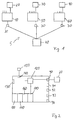
- FIG. 1 an exemplary, generally designated 5 telecommunal alarm system for three telecommunal members - hereinafter referred to as community members - is shown.
- the telecommunal alarm system 5 comprises three security monitoring modems 10, 50 and 60, which are installed, for example, in three separate houses. A certain local proximity of the houses to each other is not necessary, but it makes sense.
- Each security monitoring modem 10, 50 and 60 is via a subscriber line, in In the present case, an analog TAE socket 30, connected to a switching center 40 of a telecommunications network.
- the security monitoring modems can also be connected to the telecommunications network via a digital connection unit. As shown in FIG.
- FIG. 2 shows the block diagram of the security monitoring modem 10 shown in FIG. 1 in simplified form. It should be noted that all security monitoring modems are constructed essentially the same.
- the security monitoring modem 10 has, for example, four input connections 90, 91, 92, 93, to each of which a detector 20 or alarm transmitter can be connected. In the present case, the detector 20 is only connected to the input connection 90. As will be described in more detail below, the detector 20 serves, for example, to report a broken glass.
- Another input connection 94 is for switching on a sabotage line with which, for example, the detector 20 is monitored and thus the security monitoring modem 10 can be protected against willful interference.
- the security monitoring modem 10 has a first memory 100, in which the phone numbers of the two other security monitoring modems 50 and 60, ie the two other community members, are stored.
- a second memory 110 contains a message for Identification of the security monitoring modem 10 or the community member.
- the identification message includes, for example, the call number of the community member with whom the security monitoring modem 10 is installed.
- the identification message can contain the name and address of the respective community member.
- an individual alarm message can be stored in text form, which corresponds to the alarm state that can be detected by the detector 20.
- the alarm message "broken glass” is therefore stored in memory 160. If detectors 91 to 93 are connected to the other input connections, the corresponding individual alarm messages can be stored in text form in the memory 160. Each alarm message stored in the memory 160 is uniquely assigned to one of the input connections 90-93. It should also be noted that all input connections 90 to 94 are programmable as normally open or normally closed. This means, for example, that the detector 20, which is connected to the input connection 90 programmed as a normally open contact, reports an alarm state if the monitored loop is interrupted as a result of glass breakage. In contrast, a detector connected to an input port programmed as a break contact reports an alarm condition when the monitored loop is closed.
- a fourth memory, designated 170 which serves as a so-called log memory
- all outgoing messages arriving at the security monitoring modem 10 are recorded within a predetermined period of time, advantageously during 24 hours.
- Each security monitoring modem 10, 50, 60 can have an LCD display, a plurality of acoustic (for example an internal loudspeaker) and optical display devices (light-emitting diodes and light fields for status display, all of which are not shown).
- Telecommunal alarm system 5 The operation of the invention Telecommunal alarm system 5 is explained in more detail below.
- the telecommunications community consists of three members, each with a security monitoring modem 10, 50 or 60 installed.
- the name of the first member is F. Müller, residing at Kestrasse 17.
- the second member is G. Stephan and lives at Goethestrasse 7.
- the third member is A. Meier and lives at Kestrasse 22.
- the security surveillance modem 10 is installed on the member F. Müller, the security surveillance modem 50 is installed on the member G. Stephan and the security surveillance modem 60 is installed on the member A. Meier.
- each security monitoring modem can be programmed on site using a keyboard (not shown) or with a terminal program using an externally connectable computer. It is advisable to password protect the programming.
- the programming of the security monitoring modem essentially determines to which of the input connections 90 to 93 a detector is connected, how it behaves (as a make contact or a break contact) and which numbers to dial in which order are. To uniquely identify each security monitoring modem, the corresponding phone number and, if applicable, the area code can also be entered.
- the telecommunications community member F The telecommunications community member F.
- the alarm messages can be stored in the memory 160 in text form, which correspond to the alarm states (eg entering the door or property) of the respective detector. 5.
- F. Müller activated his security monitoring modem 10.
- the safety monitoring modem automatically carries out a device test and shows the errors that may occur on the LCD display.
- the second member G. Stephan writes the number 1166 for F. Müller and the number 4455 for member A. Meier in the first memory 100 of his security monitoring modem 50. An area code is not required because the community members all live in the same place.
- the second memory 110 of the security monitoring modem 50 contains, for example, the name G.
- the third memory 160 the alarm messages belonging to the respective connected detectors can again be in text form.
- A. Meier the third member of the telecommunications community, programs his security monitoring modem 60 in such a way that the first memory 100 contains the number 1166 of the member F. Müller and the telephone number 2233 of the other member G. Stephan.
- the second memory 110 contains its own identification message, ie the name A. Meier, the telephone number 4455 and the address, ieGart Avenue 22.
- the third memory 160 can be programmed with the corresponding alarm messages in text form. We provide let us now consider the following scenario that an intruder broke a window of member F. Müller's apartment.
- the siren 150 or an all-round light is activated, which signals a break-in acoustically or optically in this way.
- the detector 20 reports a broken glass to the control device 120.
- the control device 120 is programmed, for example, in such a way that it automatically dials the two numbers of the other telegemunity members stored in the memory 100 in the order specified, ie first the number 2233 and then the number 4455.
- the security monitoring modem 10 immediately establishes a dial-up connection to the security monitoring modem 50 after the glass 20 is signaled by the detector 20.
- the control device 120 ensures that the identification message stored in the memory 110 (this includes the name F.
- the security monitoring modem 10 dials the number 4455 of the security monitoring modem 60, which, although it has alarmed from the security monitoring modem 10, has not yet sent any confirmation of the alarm message there. After the dial-up connection has been set up, the security monitoring modem 10 transmits the message "alarm has been acknowledged" to the security monitoring modem 60. Now that the member G. Stephan has been alerted to the intrusion at F. Müller, the latter can take the necessary measures by he z. B. notifies the police. After the security monitoring modem 10 has transmitted the all-clear message to the security monitoring modem 60, it automatically returns to its operational readiness. In the event of a further alarm detection by the detector 20, the above-mentioned procedure is carried out again.
Landscapes
- Business, Economics & Management (AREA)
- Emergency Management (AREA)
- Physics & Mathematics (AREA)
- General Physics & Mathematics (AREA)
- Alarm Systems (AREA)
- Telephonic Communication Services (AREA)
Applications Claiming Priority (2)
| Application Number | Priority Date | Filing Date | Title |
|---|---|---|---|
| DE19611271 | 1996-03-22 | ||
| DE19611271A DE19611271A1 (de) | 1996-03-22 | 1996-03-22 | Telegemeinschafts-Alarmsystem mit mehreren Sicherheits-Überwachungsmodems |
Publications (2)
| Publication Number | Publication Date |
|---|---|
| EP0797178A1 true EP0797178A1 (fr) | 1997-09-24 |
| EP0797178B1 EP0797178B1 (fr) | 2001-11-07 |
Family
ID=7789052
Family Applications (1)
| Application Number | Title | Priority Date | Filing Date |
|---|---|---|---|
| EP96117949A Expired - Lifetime EP0797178B1 (fr) | 1996-03-22 | 1996-11-08 | Système d'alarme pour télécommunauté avec plusieurs modems de surveillance de sécurité |
Country Status (5)
| Country | Link |
|---|---|
| US (1) | US5939980A (fr) |
| EP (1) | EP0797178B1 (fr) |
| JP (1) | JPH1021484A (fr) |
| AT (1) | ATE208523T1 (fr) |
| DE (2) | DE19611271A1 (fr) |
Families Citing this family (16)
| Publication number | Priority date | Publication date | Assignee | Title |
|---|---|---|---|---|
| US6237034B1 (en) * | 1997-11-04 | 2001-05-22 | Nortel Networks Limited | Method and system for transmitting and receiving alarm notifications and acknowledgements within a telecommunications network |
| WO1999034339A2 (fr) | 1997-12-29 | 1999-07-08 | Ameritech Corporation | Systeme de domotique et de telesecurite residentielle et procede associe |
| US7349682B1 (en) * | 1998-06-12 | 2008-03-25 | Sbc Properties, L.P. | Home gateway system for automation and security |
| US6650743B2 (en) * | 2000-06-09 | 2003-11-18 | Ameritech Corporation | Method of providing caller identification for calls placed over an internet |
| US6166632A (en) * | 1998-10-02 | 2000-12-26 | Chen; Tai-Sheng | Interactive alarm systems |
| US20020007459A1 (en) * | 2000-07-17 | 2002-01-17 | Cassista Gerard R. | Method and apparatus for intentional blockage of connectivity |
| NL1016632C2 (nl) * | 2000-11-17 | 2002-05-22 | Reinder Eric Nederhoed | Alarmeringsinrichting. |
| RU2215329C2 (ru) * | 2001-12-13 | 2003-10-27 | Научно-исследовательский центр "Охрана Главного управления вневедомственной охраны МВД России" | Универсальный ретранслятор системы передачи тревожных сообщений |
| AU2003245113B2 (en) * | 2002-07-29 | 2007-06-21 | Carrier Corporation | A telemetry system |
| AU2007203059B2 (en) * | 2002-07-29 | 2010-09-23 | Carrier Corporation | A Telemetry System |
| WO2004012434A1 (fr) * | 2002-07-29 | 2004-02-05 | Uhs Systems Pty Ltd | Systeme de telemetrie |
| RU2231125C2 (ru) * | 2002-08-30 | 2004-06-20 | ОАО "Центр Телеком" | Устройство для передачи сигналов тревожных сообщений по занятым цифровым каналам связи |
| US6870476B2 (en) * | 2003-04-07 | 2005-03-22 | Bulldog Technologies Inc. | Continuous feedback container security system |
| BE1015557A5 (nl) * | 2003-06-10 | 2005-06-07 | Neve Frank De | Werkwijze en middelen voor het uitvoeren van een bewaking of een meldingsopdracht. |
| US7561038B2 (en) * | 2003-07-21 | 2009-07-14 | Uhs Systems Pty Limited | Telemetry system |
| CN108334011A (zh) * | 2017-01-17 | 2018-07-27 | 淮安信息职业技术学院 | 一种智慧社区监控管理集中化监控台 |
Citations (2)
| Publication number | Priority date | Publication date | Assignee | Title |
|---|---|---|---|---|
| EP0296022A1 (fr) * | 1987-06-17 | 1988-12-21 | René Duranton | Dispositif d'adressage sur bus |
| FR2633762A1 (fr) * | 1988-06-30 | 1990-01-05 | Quebec Inc 2625 4219 | Systeme de securite automatise pour voisinage |
Family Cites Families (8)
| Publication number | Priority date | Publication date | Assignee | Title |
|---|---|---|---|---|
| US4558181A (en) * | 1983-04-27 | 1985-12-10 | Phonetics, Inc. | Portable device for monitoring local area |
| US4731810A (en) * | 1986-02-25 | 1988-03-15 | Watkins Randy W | Neighborhood home security system |
| US4742336A (en) * | 1986-12-04 | 1988-05-03 | Hall Security Services, Inc. | Portable intrusion detection warning system |
| US4951029A (en) * | 1988-02-16 | 1990-08-21 | Interactive Technologies, Inc. | Micro-programmable security system |
| CA1333296C (fr) * | 1988-11-15 | 1994-11-29 | Dawn Smith | Systeme pour avertir un groupe de personnes en cas d'urgence |
| SE9300964D0 (sv) * | 1993-03-23 | 1993-03-23 | Jan Ruus | Larmsystem |
| DE9320041U1 (de) * | 1993-12-28 | 1994-04-14 | Hornschild, Dieter, 53619 Rheinbreitbach | Alarmtelefon |
| DE9412327U1 (de) * | 1994-07-30 | 1994-10-27 | Richter, Thorsten, 38165 Lehre | Telekommunikationsvorrichtung zur Sicherheitsüberwachung und Warnung |
-
1996
- 1996-03-22 DE DE19611271A patent/DE19611271A1/de not_active Withdrawn
- 1996-11-08 AT AT96117949T patent/ATE208523T1/de not_active IP Right Cessation
- 1996-11-08 EP EP96117949A patent/EP0797178B1/fr not_active Expired - Lifetime
- 1996-11-08 DE DE59608142T patent/DE59608142D1/de not_active Expired - Lifetime
-
1997
- 1997-03-17 JP JP9062587A patent/JPH1021484A/ja active Pending
- 1997-03-20 US US08/820,862 patent/US5939980A/en not_active Expired - Lifetime
Patent Citations (2)
| Publication number | Priority date | Publication date | Assignee | Title |
|---|---|---|---|---|
| EP0296022A1 (fr) * | 1987-06-17 | 1988-12-21 | René Duranton | Dispositif d'adressage sur bus |
| FR2633762A1 (fr) * | 1988-06-30 | 1990-01-05 | Quebec Inc 2625 4219 | Systeme de securite automatise pour voisinage |
Also Published As
| Publication number | Publication date |
|---|---|
| JPH1021484A (ja) | 1998-01-23 |
| ATE208523T1 (de) | 2001-11-15 |
| DE19611271A1 (de) | 1997-09-25 |
| US5939980A (en) | 1999-08-17 |
| DE59608142D1 (de) | 2001-12-13 |
| EP0797178B1 (fr) | 2001-11-07 |
Similar Documents
| Publication | Publication Date | Title |
|---|---|---|
| EP0797178B1 (fr) | Système d'alarme pour télécommunauté avec plusieurs modems de surveillance de sécurité | |
| DE19908179A1 (de) | Überwachungsanordnung für ein Sicherheitsverbundsystem | |
| CH652547A5 (de) | Verfahren zum ueberwachen von raeumlichkeiten mittels einer telefonleitung. | |
| DE3231591A1 (de) | Sicherheitssystem | |
| DE3921658A1 (de) | Automatisches schutzsystem | |
| DE4423947A1 (de) | Einbruchmeldeanlage | |
| DE19523980C1 (de) | Verfahren zur Überwachung von Objekten über eine Datenfernübertragungsleitung | |
| DE3332268A1 (de) | Alarmmeldeanlage | |
| DE69713405T2 (de) | Videosicherheitssystem | |
| EP0554948A1 (fr) | Dispositif pour la télésurveillance de locaux | |
| EP0236878B1 (fr) | Petit central téléphonique privé, en particulier central à postes à lignes multiples | |
| DE19522113C1 (de) | Anlage zum Überwachen und Alarmieren bei Störungen innerhalb eines überwachten Bereichs | |
| DE2952725A1 (de) | Objektschutzeinrichtung, insbesondere fuer gebaeude, wohnhaeuser o.dgl. | |
| DE2923732A1 (de) | Alarmanlage | |
| EP0296153B1 (fr) | Poste d'abonne au teletexte | |
| DE19646091B4 (de) | Hausnotrufanlage | |
| WO1998030011A2 (fr) | Procede de surveillance d'un objet par l'intermediare d'un reseau informatique numerique | |
| DE3415819A1 (de) | Brandmeldeeinrichtung | |
| DE19704109A1 (de) | Signalauswerte- und Übertragungseinrichtung | |
| EP0817147A1 (fr) | Système d'alarme sans fil à réception d'alarme à distance | |
| DE4333580C2 (de) | Verfahren und System zur automatischen Überwachung zumindest eines Computers | |
| EP0676734A1 (fr) | Système et procédé pour alerter | |
| DE19654721C1 (de) | Verfahren zum Überwachen eines Objektes über ein digitales Datennetz | |
| DE2512296A1 (de) | Fernueberwachungsanlage, insbesondere zur ueberwachung von kassenraeumen in banken oder aehnlichem | |
| DE3149225A1 (de) | Hausmeldesystem (hms) |
Legal Events
| Date | Code | Title | Description |
|---|---|---|---|
| PUAI | Public reference made under article 153(3) epc to a published international application that has entered the european phase |
Free format text: ORIGINAL CODE: 0009012 |
|
| AK | Designated contracting states |
Kind code of ref document: A1 Designated state(s): AT BE CH DE DK ES FI FR GB GR IE IT LI LU MC NL PT SE |
|
| 17P | Request for examination filed |
Effective date: 19980324 |
|
| 17Q | First examination report despatched |
Effective date: 20000524 |
|
| GRAG | Despatch of communication of intention to grant |
Free format text: ORIGINAL CODE: EPIDOS AGRA |
|
| GRAG | Despatch of communication of intention to grant |
Free format text: ORIGINAL CODE: EPIDOS AGRA |
|
| GRAH | Despatch of communication of intention to grant a patent |
Free format text: ORIGINAL CODE: EPIDOS IGRA |
|
| GRAH | Despatch of communication of intention to grant a patent |
Free format text: ORIGINAL CODE: EPIDOS IGRA |
|
| GRAA | (expected) grant |
Free format text: ORIGINAL CODE: 0009210 |
|
| AK | Designated contracting states |
Kind code of ref document: B1 Designated state(s): AT BE CH DE DK ES FI FR GB GR IE IT LI LU MC NL PT SE |
|
| PG25 | Lapsed in a contracting state [announced via postgrant information from national office to epo] |
Ref country code: NL Free format text: LAPSE BECAUSE OF FAILURE TO SUBMIT A TRANSLATION OF THE DESCRIPTION OR TO PAY THE FEE WITHIN THE PRESCRIBED TIME-LIMIT Effective date: 20011107 Ref country code: IT Free format text: LAPSE BECAUSE OF FAILURE TO SUBMIT A TRANSLATION OF THE DESCRIPTION OR TO PAY THE FEE WITHIN THE PRE;WARNING: LAPSES OF ITALIAN PATENTS WITH EFFECTIVE DATE BEFORE 2007 MAY HAVE OCCURRED AT ANY TIME BEFORE 2007. THE CORRECT EFFECTIVE DATE MAY BE DIFFERENT FROM THE ONE RECORDED.SCRIBED TIME-LIMIT Effective date: 20011107 Ref country code: IE Free format text: LAPSE BECAUSE OF FAILURE TO SUBMIT A TRANSLATION OF THE DESCRIPTION OR TO PAY THE FEE WITHIN THE PRESCRIBED TIME-LIMIT Effective date: 20011107 Ref country code: GR Free format text: LAPSE BECAUSE OF FAILURE TO SUBMIT A TRANSLATION OF THE DESCRIPTION OR TO PAY THE FEE WITHIN THE PRESCRIBED TIME-LIMIT Effective date: 20011107 Ref country code: GB Free format text: LAPSE BECAUSE OF FAILURE TO SUBMIT A TRANSLATION OF THE DESCRIPTION OR TO PAY THE FEE WITHIN THE PRESCRIBED TIME-LIMIT Effective date: 20011107 Ref country code: FR Free format text: LAPSE BECAUSE OF FAILURE TO SUBMIT A TRANSLATION OF THE DESCRIPTION OR TO PAY THE FEE WITHIN THE PRESCRIBED TIME-LIMIT Effective date: 20011107 Ref country code: FI Free format text: LAPSE BECAUSE OF FAILURE TO SUBMIT A TRANSLATION OF THE DESCRIPTION OR TO PAY THE FEE WITHIN THE PRESCRIBED TIME-LIMIT Effective date: 20011107 |
|
| REF | Corresponds to: |
Ref document number: 208523 Country of ref document: AT Date of ref document: 20011115 Kind code of ref document: T |
|
| PG25 | Lapsed in a contracting state [announced via postgrant information from national office to epo] |
Ref country code: MC Free format text: LAPSE BECAUSE OF NON-PAYMENT OF DUE FEES Effective date: 20011108 Ref country code: LU Free format text: LAPSE BECAUSE OF NON-PAYMENT OF DUE FEES Effective date: 20011108 Ref country code: AT Free format text: LAPSE BECAUSE OF NON-PAYMENT OF DUE FEES Effective date: 20011108 |
|
| REG | Reference to a national code |
Ref country code: CH Ref legal event code: EP |
|
| PG25 | Lapsed in a contracting state [announced via postgrant information from national office to epo] |
Ref country code: LI Free format text: LAPSE BECAUSE OF NON-PAYMENT OF DUE FEES Effective date: 20011130 Ref country code: CH Free format text: LAPSE BECAUSE OF NON-PAYMENT OF DUE FEES Effective date: 20011130 Ref country code: BE Free format text: LAPSE BECAUSE OF NON-PAYMENT OF DUE FEES Effective date: 20011130 |
|
| REG | Reference to a national code |
Ref country code: IE Ref legal event code: FG4D Free format text: GERMAN |
|
| REF | Corresponds to: |
Ref document number: 59608142 Country of ref document: DE Date of ref document: 20011213 |
|
| REG | Reference to a national code |
Ref country code: GB Ref legal event code: IF02 |
|
| PG25 | Lapsed in a contracting state [announced via postgrant information from national office to epo] |
Ref country code: SE Free format text: LAPSE BECAUSE OF FAILURE TO SUBMIT A TRANSLATION OF THE DESCRIPTION OR TO PAY THE FEE WITHIN THE PRESCRIBED TIME-LIMIT Effective date: 20020207 Ref country code: PT Free format text: LAPSE BECAUSE OF FAILURE TO SUBMIT A TRANSLATION OF THE DESCRIPTION OR TO PAY THE FEE WITHIN THE PRESCRIBED TIME-LIMIT Effective date: 20020207 Ref country code: DK Free format text: LAPSE BECAUSE OF FAILURE TO SUBMIT A TRANSLATION OF THE DESCRIPTION OR TO PAY THE FEE WITHIN THE PRESCRIBED TIME-LIMIT Effective date: 20020207 |
|
| NLV1 | Nl: lapsed or annulled due to failure to fulfill the requirements of art. 29p and 29m of the patents act | ||
| GBV | Gb: ep patent (uk) treated as always having been void in accordance with gb section 77(7)/1977 [no translation filed] |
Effective date: 20011107 |
|
| PG25 | Lapsed in a contracting state [announced via postgrant information from national office to epo] |
Ref country code: ES Free format text: LAPSE BECAUSE OF FAILURE TO SUBMIT A TRANSLATION OF THE DESCRIPTION OR TO PAY THE FEE WITHIN THE PRESCRIBED TIME-LIMIT Effective date: 20020530 |
|
| BERE | Be: lapsed |
Owner name: DEUTSCHE TELEKOM A.G. Effective date: 20011130 |
|
| REG | Reference to a national code |
Ref country code: CH Ref legal event code: PL |
|
| REG | Reference to a national code |
Ref country code: IE Ref legal event code: FD4D |
|
| EN | Fr: translation not filed | ||
| PLBE | No opposition filed within time limit |
Free format text: ORIGINAL CODE: 0009261 |
|
| STAA | Information on the status of an ep patent application or granted ep patent |
Free format text: STATUS: NO OPPOSITION FILED WITHIN TIME LIMIT |
|
| 26N | No opposition filed | ||
| PGFP | Annual fee paid to national office [announced via postgrant information from national office to epo] |
Ref country code: DE Payment date: 20151119 Year of fee payment: 20 |
|
| REG | Reference to a national code |
Ref country code: DE Ref legal event code: R071 Ref document number: 59608142 Country of ref document: DE |