EP0797184A2 - Schwingungs-/Lärmkontrolleanordnung - Google Patents
Schwingungs-/Lärmkontrolleanordnung Download PDFInfo
- Publication number
- EP0797184A2 EP0797184A2 EP97104676A EP97104676A EP0797184A2 EP 0797184 A2 EP0797184 A2 EP 0797184A2 EP 97104676 A EP97104676 A EP 97104676A EP 97104676 A EP97104676 A EP 97104676A EP 0797184 A2 EP0797184 A2 EP 0797184A2
- Authority
- EP
- European Patent Office
- Prior art keywords
- filter
- vibration
- dynamic characteristic
- signal
- identifying
- Prior art date
- Legal status (The legal status is an assumption and is not a legal conclusion. Google has not performed a legal analysis and makes no representation as to the accuracy of the status listed.)
- Granted
Links
- 230000003044 adaptive effect Effects 0.000 claims abstract description 54
- 230000005540 biological transmission Effects 0.000 claims abstract description 40
- 238000012546 transfer Methods 0.000 claims abstract description 37
- 230000002068 genetic effect Effects 0.000 claims abstract description 10
- 230000003111 delayed effect Effects 0.000 claims description 41
- 238000001514 detection method Methods 0.000 claims description 6
- 230000001419 dependent effect Effects 0.000 claims description 4
- 238000012545 processing Methods 0.000 abstract description 46
- 230000032683 aging Effects 0.000 description 13
- 238000005070 sampling Methods 0.000 description 10
- 238000004880 explosion Methods 0.000 description 5
- 238000010586 diagram Methods 0.000 description 4
- 108090000623 proteins and genes Proteins 0.000 description 4
- 238000002485 combustion reaction Methods 0.000 description 3
- 238000000034 method Methods 0.000 description 3
- 230000035772 mutation Effects 0.000 description 3
- 238000004364 calculation method Methods 0.000 description 2
- 238000006243 chemical reaction Methods 0.000 description 2
- 230000001934 delay Effects 0.000 description 2
- 230000001788 irregular Effects 0.000 description 2
- 239000007788 liquid Substances 0.000 description 2
- 238000012937 correction Methods 0.000 description 1
- 230000007613 environmental effect Effects 0.000 description 1
- 230000001747 exhibiting effect Effects 0.000 description 1
- 238000001914 filtration Methods 0.000 description 1
- 238000009499 grossing Methods 0.000 description 1
- 238000007430 reference method Methods 0.000 description 1
- 239000000725 suspension Substances 0.000 description 1
Images


Classifications
-
- F—MECHANICAL ENGINEERING; LIGHTING; HEATING; WEAPONS; BLASTING
- F16—ENGINEERING ELEMENTS AND UNITS; GENERAL MEASURES FOR PRODUCING AND MAINTAINING EFFECTIVE FUNCTIONING OF MACHINES OR INSTALLATIONS; THERMAL INSULATION IN GENERAL
- F16F—SPRINGS; SHOCK-ABSORBERS; MEANS FOR DAMPING VIBRATION
- F16F15/00—Suppression of vibrations in systems; Means or arrangements for avoiding or reducing out-of-balance forces, e.g. due to motion
- F16F15/02—Suppression of vibrations of non-rotating, e.g. reciprocating systems; Suppression of vibrations of rotating systems by use of members not moving with the rotating systems
-
- G—PHYSICS
- G10—MUSICAL INSTRUMENTS; ACOUSTICS
- G10K—SOUND-PRODUCING DEVICES; METHODS OR DEVICES FOR PROTECTING AGAINST, OR FOR DAMPING, NOISE OR OTHER ACOUSTIC WAVES IN GENERAL; ACOUSTICS NOT OTHERWISE PROVIDED FOR
- G10K11/00—Methods or devices for transmitting, conducting or directing sound in general; Methods or devices for protecting against, or for damping, noise or other acoustic waves in general
- G10K11/16—Methods or devices for protecting against, or for damping, noise or other acoustic waves in general
- G10K11/175—Methods or devices for protecting against, or for damping, noise or other acoustic waves in general using interference effects; Masking sound
- G10K11/178—Methods or devices for protecting against, or for damping, noise or other acoustic waves in general using interference effects; Masking sound by electro-acoustically regenerating the original acoustic waves in anti-phase
- G10K11/1781—Methods or devices for protecting against, or for damping, noise or other acoustic waves in general using interference effects; Masking sound by electro-acoustically regenerating the original acoustic waves in anti-phase characterised by the analysis of input or output signals, e.g. frequency range, modes, transfer functions
- G10K11/17813—Methods or devices for protecting against, or for damping, noise or other acoustic waves in general using interference effects; Masking sound by electro-acoustically regenerating the original acoustic waves in anti-phase characterised by the analysis of input or output signals, e.g. frequency range, modes, transfer functions characterised by the analysis of the acoustic paths, e.g. estimating, calibrating or testing of transfer functions or cross-terms
- G10K11/17817—Methods or devices for protecting against, or for damping, noise or other acoustic waves in general using interference effects; Masking sound by electro-acoustically regenerating the original acoustic waves in anti-phase characterised by the analysis of input or output signals, e.g. frequency range, modes, transfer functions characterised by the analysis of the acoustic paths, e.g. estimating, calibrating or testing of transfer functions or cross-terms between the output signals and the error signals, i.e. secondary path
-
- G—PHYSICS
- G10—MUSICAL INSTRUMENTS; ACOUSTICS
- G10K—SOUND-PRODUCING DEVICES; METHODS OR DEVICES FOR PROTECTING AGAINST, OR FOR DAMPING, NOISE OR OTHER ACOUSTIC WAVES IN GENERAL; ACOUSTICS NOT OTHERWISE PROVIDED FOR
- G10K11/00—Methods or devices for transmitting, conducting or directing sound in general; Methods or devices for protecting against, or for damping, noise or other acoustic waves in general
- G10K11/16—Methods or devices for protecting against, or for damping, noise or other acoustic waves in general
- G10K11/175—Methods or devices for protecting against, or for damping, noise or other acoustic waves in general using interference effects; Masking sound
- G10K11/178—Methods or devices for protecting against, or for damping, noise or other acoustic waves in general using interference effects; Masking sound by electro-acoustically regenerating the original acoustic waves in anti-phase
- G10K11/1785—Methods, e.g. algorithms; Devices
- G10K11/17853—Methods, e.g. algorithms; Devices of the filter
- G10K11/17854—Methods, e.g. algorithms; Devices of the filter the filter being an adaptive filter
-
- G—PHYSICS
- G10—MUSICAL INSTRUMENTS; ACOUSTICS
- G10K—SOUND-PRODUCING DEVICES; METHODS OR DEVICES FOR PROTECTING AGAINST, OR FOR DAMPING, NOISE OR OTHER ACOUSTIC WAVES IN GENERAL; ACOUSTICS NOT OTHERWISE PROVIDED FOR
- G10K11/00—Methods or devices for transmitting, conducting or directing sound in general; Methods or devices for protecting against, or for damping, noise or other acoustic waves in general
- G10K11/16—Methods or devices for protecting against, or for damping, noise or other acoustic waves in general
- G10K11/175—Methods or devices for protecting against, or for damping, noise or other acoustic waves in general using interference effects; Masking sound
- G10K11/178—Methods or devices for protecting against, or for damping, noise or other acoustic waves in general using interference effects; Masking sound by electro-acoustically regenerating the original acoustic waves in anti-phase
- G10K11/1785—Methods, e.g. algorithms; Devices
- G10K11/17855—Methods, e.g. algorithms; Devices for improving speed or power requirements
-
- G—PHYSICS
- G10—MUSICAL INSTRUMENTS; ACOUSTICS
- G10K—SOUND-PRODUCING DEVICES; METHODS OR DEVICES FOR PROTECTING AGAINST, OR FOR DAMPING, NOISE OR OTHER ACOUSTIC WAVES IN GENERAL; ACOUSTICS NOT OTHERWISE PROVIDED FOR
- G10K11/00—Methods or devices for transmitting, conducting or directing sound in general; Methods or devices for protecting against, or for damping, noise or other acoustic waves in general
- G10K11/16—Methods or devices for protecting against, or for damping, noise or other acoustic waves in general
- G10K11/175—Methods or devices for protecting against, or for damping, noise or other acoustic waves in general using interference effects; Masking sound
- G10K11/178—Methods or devices for protecting against, or for damping, noise or other acoustic waves in general using interference effects; Masking sound by electro-acoustically regenerating the original acoustic waves in anti-phase
- G10K11/1787—General system configurations
- G10K11/17879—General system configurations using both a reference signal and an error signal
- G10K11/17883—General system configurations using both a reference signal and an error signal the reference signal being derived from a machine operating condition, e.g. engine RPM or vehicle speed
-
- G—PHYSICS
- G10—MUSICAL INSTRUMENTS; ACOUSTICS
- G10K—SOUND-PRODUCING DEVICES; METHODS OR DEVICES FOR PROTECTING AGAINST, OR FOR DAMPING, NOISE OR OTHER ACOUSTIC WAVES IN GENERAL; ACOUSTICS NOT OTHERWISE PROVIDED FOR
- G10K2210/00—Details of active noise control [ANC] covered by G10K11/178 but not provided for in any of its subgroups
- G10K2210/10—Applications
- G10K2210/121—Rotating machines, e.g. engines, turbines, motors; Periodic or quasi-periodic signals in general
-
- G—PHYSICS
- G10—MUSICAL INSTRUMENTS; ACOUSTICS
- G10K—SOUND-PRODUCING DEVICES; METHODS OR DEVICES FOR PROTECTING AGAINST, OR FOR DAMPING, NOISE OR OTHER ACOUSTIC WAVES IN GENERAL; ACOUSTICS NOT OTHERWISE PROVIDED FOR
- G10K2210/00—Details of active noise control [ANC] covered by G10K11/178 but not provided for in any of its subgroups
- G10K2210/10—Applications
- G10K2210/128—Vehicles
- G10K2210/1282—Automobiles
-
- G—PHYSICS
- G10—MUSICAL INSTRUMENTS; ACOUSTICS
- G10K—SOUND-PRODUCING DEVICES; METHODS OR DEVICES FOR PROTECTING AGAINST, OR FOR DAMPING, NOISE OR OTHER ACOUSTIC WAVES IN GENERAL; ACOUSTICS NOT OTHERWISE PROVIDED FOR
- G10K2210/00—Details of active noise control [ANC] covered by G10K11/178 but not provided for in any of its subgroups
- G10K2210/10—Applications
- G10K2210/129—Vibration, e.g. instead of, or in addition to, acoustic noise
- G10K2210/1291—Anti-Vibration-Control, e.g. reducing vibrations in panels or beams
-
- G—PHYSICS
- G10—MUSICAL INSTRUMENTS; ACOUSTICS
- G10K—SOUND-PRODUCING DEVICES; METHODS OR DEVICES FOR PROTECTING AGAINST, OR FOR DAMPING, NOISE OR OTHER ACOUSTIC WAVES IN GENERAL; ACOUSTICS NOT OTHERWISE PROVIDED FOR
- G10K2210/00—Details of active noise control [ANC] covered by G10K11/178 but not provided for in any of its subgroups
- G10K2210/30—Means
- G10K2210/301—Computational
- G10K2210/3023—Estimation of noise, e.g. on error signals
- G10K2210/30232—Transfer functions, e.g. impulse response
-
- G—PHYSICS
- G10—MUSICAL INSTRUMENTS; ACOUSTICS
- G10K—SOUND-PRODUCING DEVICES; METHODS OR DEVICES FOR PROTECTING AGAINST, OR FOR DAMPING, NOISE OR OTHER ACOUSTIC WAVES IN GENERAL; ACOUSTICS NOT OTHERWISE PROVIDED FOR
- G10K2210/00—Details of active noise control [ANC] covered by G10K11/178 but not provided for in any of its subgroups
- G10K2210/30—Means
- G10K2210/321—Physical
- G10K2210/3211—Active mounts for vibrating structures with means to actively suppress the vibration, e.g. for vehicles
-
- G—PHYSICS
- G10—MUSICAL INSTRUMENTS; ACOUSTICS
- G10K—SOUND-PRODUCING DEVICES; METHODS OR DEVICES FOR PROTECTING AGAINST, OR FOR DAMPING, NOISE OR OTHER ACOUSTIC WAVES IN GENERAL; ACOUSTICS NOT OTHERWISE PROVIDED FOR
- G10K2210/00—Details of active noise control [ANC] covered by G10K11/178 but not provided for in any of its subgroups
- G10K2210/50—Miscellaneous
- G10K2210/502—Ageing, e.g. of the control system
-
- G—PHYSICS
- G10—MUSICAL INSTRUMENTS; ACOUSTICS
- G10K—SOUND-PRODUCING DEVICES; METHODS OR DEVICES FOR PROTECTING AGAINST, OR FOR DAMPING, NOISE OR OTHER ACOUSTIC WAVES IN GENERAL; ACOUSTICS NOT OTHERWISE PROVIDED FOR
- G10K2210/00—Details of active noise control [ANC] covered by G10K11/178 but not provided for in any of its subgroups
- G10K2210/50—Miscellaneous
- G10K2210/511—Narrow band, e.g. implementations for single frequency cancellation
Definitions
- This invention relates to a vibration/noise control system, and more particularly to a vibration/noise control system which actively controls vibrations and noises generated with a periodicity or a quasi-periodicity from a rotating member and the like, to thereby reduce the vibrations and noises.
- vibration/active noise control systems have intensively been developed in various fields of the industry, which are adapted to damp vibrations and noises produced from vibration/noise sources, by the use of an adaptive digital filter (hereinafter referred to as "ADF"), to thereby reduce the vibrations and noises.
- ADF adaptive digital filter
- the W filter of a Finite Impulse Response (FIR) type having two taps (filtering order number) is employed as the ADF (first filter means), and a rotation signal from a rotating member is detected in the form of a pulse signal whenever the rotating member rotates through a predetermined very small rotating angle (e.g. 3.6° ).
- FIR Finite Impulse Response
- a sine wave signal for one repetition period is generated whenever the rotating member rotates one rotation (360 degrees), and the thus generated sine wave signal and a delayed sine wave signal obtained by delaying the sine wave signal in phase by a predetermined period are input to the first filter means for executing adaptive control, whereby even with the use of the ADF having two taps, the adaptive control can be achieved, enabling a reduction in the time period required for the product-sum operation (convolution) to be carried out.
- an identifying sound is generated, which is lower in level by a predetermined amount than the background noise, so that the transfer characteristic of the noise transmission path can be identified while the active control of vibrations and noises is carried out, without the identifying sound being sensed by the passenger(s).
- vibrations and noises are generated with a periodicity or a quasi-periodicity are used to travel under various environments over a long time period, and hence the transfer characteristic of the vibration/noise transmission path changes depending on environments under which the vehicle travels.
- vibration/noise control is carried out for a vehicle in which the engine is mounted on a so-called self-expanding engine mount, there can occur a change in the elasticity of rubber members constituting part of the engine mount due to dependency thereof on the temperature, and/or hardening of the rubber members due to aging, which causes a change in the transfer characteristic.
- the transfer characteristic of vibrations and noises within the vehicle compartment delicately changes depending on various factors, such as the temperature, the humidity, open/closed states of windows of the vehicle, and seating locations of passengers and the number of the passengers.
- the proposed active noise control system copes with the above-mentioned circumstances by generating identifying sound which is lower in level by a predetermined amount than the background noise to identify the transfer characteristic of the noise transmission path while the active control of vibrations and noises is carried out, to thereby achieve adaptive control in a manner compensating for a change in the transfer characteristic due to aging, etc. to some degree.
- the identifying sound is required to have a good S/N ratio to obtain highly accurate identification results.
- the identifying sound is sensed by the passenger(s), to thereby give an uncomfortable feeling to the passenger(s).
- the proposed active noise control system which itself generates the identifying sound to identify the transfer characteristic of the vibration/noise transmission path while the active control of vibrations and noises is carried out, there is an incompatibility between the reduction of the level of the identifying sound to such a level that it is not sensed by the passenger(s) and the achievement of a good S/N ratio.
- the proposed active noise control system can achieve only a limited accuracy of identification of the transfer characteristic of the vibration/noise transmission path in response to aging change and environmental change.
- a second object of the invention is to provide a vibration/noise control system which is capable of achieving a high-speed identification of the transfer characteristic of a vibration/noise transmission path.
- a third object of the invention is to provide a vibration/noise control system which is capable of always exhibiting high controllability of vibrations and noises in response to the actual conditions by initially storing results of identification carried out during checking of an automotive vehicle with the system installed thereon, etc. and then occasionally updating the identification results.
- a fourth object of the invention is to provide a vibration/noise control system which employs good convergency especially for an FIR type ADF having two taps, thereby achieving high-speed processing.
- a vibration/noise control system for controlling vibrations and noises generated with a periodicity or a quasi-periodicity from a vibration/ noise source having at least a rotating member, including timing pulse signal-detecting means for detecting at least one timing pulse signal indicative of a period of vibrations and noises peculiar to at least one component part of the vibration/noise source, first filter means formed by an adaptive digital filter and having a filter coefficient, for generating a control signal for controlling the vibrations and noises from the vibration/noise source, electromechanical transducer means arranged in at least one of vibration/noise transmission paths through which the vibrations and noises from the vibration/noise source are transmitted, for converting the control signal into a driving signal for driving the vibration/noise source, error signal-detecting means for detecting an error signal indicative of a difference between the driving signal and a vibration/noise signal indicative of the vibrations and noises from the vibration/noise source, second
- the vibration/noise control system is characterized by comprising:
- the transfer characteristic of the vibration/noise transmission path can be identified in parallel with execution of the control of vibrations and noises without generation of an identifying sound as employed in the prior art, to thereby enable a reduction in the burden required for the identification operation. Further, the use of a different method from the method of generating an identifying sound, for identifying the transfer characteristic of the vibration/noise transmission path improves the robustness in respect of the S/N ratio, resulting in highly accurate identification results.
- the filter coefficient-updating means of the each of the first and second dynamic characteristic-identifying means updates the filter coefficient of the adaptive digital filter of the each of the first and second dynamic characteristic-identifying means, by the use of a genetic algorithm.
- the filter coefficient-updating means of the each of the first and second dynamic characteristic-identifying means calculates values of a performance function, based on a residual signal being a difference between the error signal and a quasi error signal from the first and second dynamic characteristic-identifying means, by the use of the genetic algorithm, and updates the filter coefficient of the adaptive digital filter of the each of the first and second dynamic characteristic-identifying means, according to an optimum one of the calculated values of the performance function.
- the filter coefficient-updating means of the first dynamic characteristic-identifying means updates the filter coefficient of the adaptive digital filter of the first dynamic characteristic-identifying means, based on the optimum one of the calculated values of the performance function and the at least one timing pulse signal from the timing pulse signal-detecting means
- the filter coefficient-updating means of the second dynamic characteristic-identifying means updates the filter coefficient of the adaptive digital filter of the second dynamic characteristic-identifying means, based on the optimum one of the calculated values of the performance function and the control signal from the first filter means.
- the filter coefficient-updating means of the each of the first and second dynamic characteristic-identifying means calculates the performance function such that the residual signal assumes a minimum value.
- a vibration/noise control system for controlling vibrations and noises generated with a periodicity or a quasi-periodicity from a vibration/noise source having at least a rotating member, including timing pulse signal-detecting means for detecting at least one timing pulse signal indicative of a period of vibrations and noises peculiar to at least one component part of the vibration/noise source, sine wave-generating means for generating a reference sine wave having a single repetition period dependent upon time intervals of generation of the at least one timing pulse signal, delayed sine wave-generating means for generating a delayed sine wave which is delayed by a delay period T of 1/3 ⁇ T ⁇ 1/7 relative to the reference sine wave, wherein T is a real number, first filter means formed by an adaptive digital filter having two taps and a filter coefficient, for generating a control signal for controlling the vibrations and noises from the vibration/noise source, electromechanical transducer means arranged in at least one of vibration/
- the vibration/noise control system is characterized by comprising:
- the first and second dynamic characteristic-identifying means have adaptive digital filters each having two taps.
- the identification operation can be carried out at a high speed, to thereby improve the convergency of the control.
- the delay period T is set to 1/4 of a repetition period of the reference sine wave.
- control signal is generated based on the reference sine wave having a single repetition period and a delayed sine wave which is delayed in phase by 1/4 of the repetition period relative to the reference sine wave.
- the filter coefficient-updating means of the each of the first and second dynamic characteristic-identifying means updates the filter coefficient of the adaptive digital filter of the each of the first and second dynamic characteristic-identifying means, by the use of a genetic algorithm, it is advantageous that the first filter means generates a first control signal corresponding to the reference sine wave, and a second control signal corresponding to the delayed sine wave, the filter coefficient-updating means of the first dynamic characteristic-identifying means updating the filter coefficient of the adaptive digital filter of the first dynamic characteristic-identifying means, based on the optimum one of the calculated values of the performance function and the reference sine wave or the delayed sine wave, and the filter coefficient-updating means of the second dynamic characteristic-identifying means updates the filter coefficient of the adaptive digital filter of the second dynamic characteristic-identifying means, based on the optimum one of the calculated values of the performance function and the first and second control signals.
- the vibration/noise control system includes rotational speed-detecting means for detecting rotational speed of the rotating member, based on results of the detection by the timing pulse signal-detecting means, first dynamic characteristic-storing means storing the dynamic characteristic of the physical system extending between the first filter means and the predetermined control area as a function of the rotational speed of the rotating member, second dynamic characteristic-storing means storing the dynamic characteristic of the portion of the at least one vibration/noise transmission path extending between the first filter means and the error signal-detecting means as a function of the rotational speed of the rotating member, and dynamic characteristic-updating means for updating the dynamic characteristics stored in the first and second dynamic characteristic-storing means, based on results of the identifying by said first and second dynamic characteristic-identifying means.
- values of dynamic characteristics are stored beforehand, and occasionally updated.
- values of the dynamic characteristics previously stored in the first and second dynamic characteristic-storing means can be used in the control to thereby always secure required controllability in response to the actual conditions.
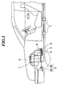
- Fig. 1 schematically shows how an engine is mounted on the chassis of an automotive vehicle, wherein the engine forms a source of vibrations and noises generated with a periodicity or a quasi-periodicity.
- reference numeral 1 designates an internal combustion engine of a four-cycle straight four-cylinder type (hereinafter simply referred to as “the engine”) as a power plant for driving an automotive vehicle.
- the engine 1 is supported on a chassis 8 by an engine mount 2, a suspension device 5 for front wheels (driving wheels) 4, and a supporting means 7 for an exhaust pipe 6.
- the engine mount 2 is comprised of a suitable number of self-expanding engine mounts 2a as electromechanical transducer means which are capable of changing a vibration/noise transfer characteristic thereof, and a suitable number of normal or known engine mounts 2b which are incapable of changing a vibration/noise transfer characteristic thereof.
- the self-expanding engine mounts 2a have respective actuators incorporated therein, which are formed of voice coil motors (VCM), piezo-electric elements, magnetostrictive elements, or the like, and operate to control vibrations of the engine according to a signal from an electronic mount control unit (hereinafter referred to as "the EMCU"), not shown, in a manner responsive to vibrations of the engine. More specifically, the self-expanding engine mounts 2a are each formed therein with a liquid chamber, not shown, which is filled with liquid, and operate to prevent vibrations from being transmitted from the engine 1 to the chassis 8, via elastic rubber members, not shown, fixed to the engine 1 (vibration/noise source) by means of the actuators.
- VCM voice coil motors
- the EMCU electronic mount control unit
- a vibration/noise error sensor 9 is arranged in the vicinity of the engine mounts 2b.
- a rotation sensor, not shown, which is formed of a magnetic sensor or the like, is arranged in the vicinity of a flywheel, not shown, fixed to a crankshaft, not shown, of the engine 1, for detecting rotation of the flywheel.
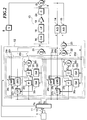
- Fig. 2 schematically shows the whole arrangement of a vibration/noise control system according to a first embodiment of the invention.
- the vibration/noise control system is comprised of the rotation sensor 10, an electronic control unit (hereinafter referred to as "the ECU") 11 for generating sampling pulses Ps defining a sampling frequency, based on a basic pulse signal X from the rotation sensor 10 and also generating two different timing pulse signals Y 1 and Y 2 corresponding to predetermined vibration orders by dividing the sampling frequency, a digital signal processor (hereinafter referred to as "the DSP") 12 which is capable of making high-speed operation to perform adaptive control upon outputting of the timing pulse signals Y 1 and Y 2 from the ECU 11 as trigger signals, a vibration/noise transmission path 13 through which passes a control signal V (digital signal) which is output from the DSP 12, the vibration/noise error sensor 9 which is supplied with the control signal V having passed through the vibration/noise transmission path 13, as a driving signal Z, as well as with a vibration noise signal D transmitted from the engine 1 through the chassis 8, and A/D converters 14 and 15 for converting an error signal ⁇ (
- the rotation sensor 10 counts teeth of a ring gear provided along the periphery of the flywheel to generate the basic pulse signal X in the form of pulses, and delivers the basic pulse signal X to the ECU 11.
- the ECU 11 generates the sampling pulse signal Ps defining the sampling frequency, based on the basic pulse signal X and delivers the signal Ps to the DSP 12 to thereby drive the system, and further divides the frequency of the sampling pulse signal Ps, based on a vibration/noise transfer characteristic peculiar to engine component parts, such as the piston system and the combustion chamber of the engine 1 (vibration source), to thereby generate two types of timing pulse signals Y 1 and Y 2 .
- the ECU 11 generates the timing pulse signal Y 1 which is suitable for controlling a vibration component (primary vibration component) caused by the piston system and having a regular vibration/noise characteristic in synchronism with rotation of the engine 1, and the timing pulse signal Y 2 which is suitable for controlling a vibration component (secondary vibration component) caused by explosion pressure (exciting force) and having an irregular vibration/noise characteristic depending on a combustion state of the engine.
- the piston system carries out one reciprocating motion per rotation of the crankshaft, and it is therefore considered that vibration of the piston system occurs once per rotation of the crankshaft.
- the timing pulse signal Y 1 for controlling the primary vibration component is generated once per rotation of the crankshaft of the engine 1.
- timing pulse signal Y 2 for controlling the secondary vibration component is generated once per half a rotation of the crankshaft of the engine 1.
- the invention employs the concept of the vibration order and carries out the adaptive control on each of a plurality of vibration orders of the vibration components, which makes it possible to reduce vibrations and noises more effectively.
- the adaptive control is separately carried out on the primary vibration component having a regular vibration noise characteristic and on the secondary vibration component, which is related to the explosion pressure and has an irregular vibration/noise characteristic, to thereby effectively reduce the vibrations and noises.
- the means for detecting the rotation of the engine 1 is not limited to a sensor of the above-mentioned type which counts the teeth of the ring gear of the flywheel, but an encoder or the like may be used for directly detecting the rotation of the crankshaft or the camshaft and generating a signal indicative of the sensed rotation.
- an encoder or the like may be used for directly detecting the rotation of the crankshaft or the camshaft and generating a signal indicative of the sensed rotation.
- the detection is susceptible to variations in the rotation which are caused by torsional vibrations of the crankshaft, etc.
- the detection is susceptible to variations in the rotation of the camshaft, though they are slight in magnitude, e.g.
- the flywheel which is rigidly fixed to the crankshaft, has a large moment of inertia and hence little suffers from variations in its rotation. Therefore, detection of the rotation signal X obtained by counting the teeth of the ring gear as employed in the present embodiment is advantageous in that it can provide a desired sampling frequency in an easier and more accurate manner.
- LPF fixed low-pass filter
- the DSP 12 is comprised of two adaptive control circuits 20 1 and 20 2 for carrying out adaptive control in synchronism with the generation period of the timing pulse signals Y 1 and Y 2 , an adder 21 for adding together control signals W 1 and W 2 output, respectively, from the adaptive control circuits 20 1 and 20 2 , an adder 22 for adding together quasi error signals ⁇ '' 1 and ⁇ '' 2 output, respectively, from the adaptive control circuits 20 1 and 20 2 to generate a quasi error signal ⁇ '', and an adder 23 for adding together the quasi error signal ⁇ '' from the adder 22 and a digital error signal ⁇ ' output from the A/D converter 15 to generate a residual signal e.
- the adaptive control circuits 20 1 and 20 2 are each comprised of a vibration/noise control block 24 1 and 24 2 , and an identifying processing block 25 1 and 25 2 .
- the vibration/noise control blocks 24 1 and 24 2 are each comprised of a W filter (first filter means) 26 1 , 26 2 for executing predetermined adaptive control upon inputting of the timing pulse signal Y 1 , Y 2 as a trigger signal to generate a control signal W 1 , W 2 , a C filter (second filter means) 27 1 , 27 2 which previously stores a transfer characteristic of the vibration/noise transmission path 13 which has been identified, the identified transfer characteristic being updated according to the rotational speed of the engine 1 in response to aging change, etc., and an LMS (Least Mean Square) processing block 28 1 , 28 2 for updating the filter coefficient of the W filter 26 1 , 26 2 , based on a reference signal ⁇ 1 ⁇ 2 output from the C filter 27 1 , 27 2 , the digital error signal ⁇ ' from the A/D converter 14, and the present filter coefficient value of the W filter 26 1 , 26 2 .
- a W filter first filter means
- the identifying processing blocks 25 1 , 25 2 are each comprised of an H system-identifying filter (first dynamic characteristic-identifying means and first dynamic characteristic-storing means) 29 1 , 29 2 which previously stores a dynamic characteristic of a physical system extending from the engine 1 to the vibration/noise error sensor 9 (predetermined control area) as a dynamic transfer characteristic, and occasionally updates the stored dynamic characteristic to generate a quasi control signal ⁇ 1 , ⁇ 2 indicative of the updated dynamic characteristic, a first genetic algorithm (GA) processing block 30 1 , 30 2 which updates the filter coefficient of the H system-identifying filter 29 1 , 29 2 , based on the residual signal e from the adder 23, a C system-identifying filter (second dynamic characteristic-identifying means and second dynamic characteristic-storing means) 31 1 , 31 2 which is supplied with the control signal W 1 , W 2 and previously stores a dynamic characteristic of the vibration/noise transmission path 13 (hereinafter referred to as "C system dynamic characteristic”) as a dynamic transfer characteristic and occasionally updates the stored dynamic characteristic to generate a quasi reference signal
- the H system-identifying filter 29 1 , 29 2 and the C system-identifying filter 31 1 , 31 2 store the H system dynamic characteristic and the C system dynamic characteristic, respectively, as a function of a frequency corresponding to the rotational speed of the engine 1.
- Results of an identification carried out by an identifying method, hereinafter described, are delivered from the C system-identifying filter 31 1 , 31 2 to the C filter 27 1 , 27 2 of the vibration/noise control block 24 1 , 24 2 , where they are copied and the filter coefficient of the C filter 27 1 , 27 2 is updated thereby.
- the vibration/noise control by the vibration/noise control block 24 1 , 24 2 is preferentially executed.
- the identifying processing is executed during a time period when no arithmetic operation is substantially carried out by the LMS processing block 28 1 , 28 2 after the updated value of the filter coefficient of the W filter 26 1 , 26 2 is converged.
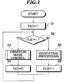
- Fig. 3 shows a program for selectively executing the vibration/noise control and the identifying processing. This program is executed in synchronism with generation of the timing pulse signal Y 1 , Y 2 .
- a flag FLG is set to "1" at a step S1.
- step S2 it is determined whether or not the flag FLG has been set to "1".
- the flag has just been set to "1"
- the answer to the question of the step S2 is affirmative (YES)
- step S3 the vibration/noise control is executed.
- step S4 the flag FLG is set to "0", followed by the program returning to the step S2. Then, the answer to the question of the step S2 becomes negative (NO), and therefore the program proceeds to a step S5, wherein the identifying processing is executed.
- the program proceeds to a step S6 to set the flag FLG to "1", followed by the program again returning to the step S2 to thereby repeatedly execute the above processing.
- the vibration/noise control and the identifying processing are alternately executed, utilizing the time intervals of generation of the timing pulse signal Y 1 , Y 2 .
- the vibration/noise control block 24 1 , 24 2 is allowed to perform its control with priority to the identifying processing block 25 1 , 25 2 . Therefore, even when the identifying processing block 25 1 , 25 2 is operating, if the flag FLG is set to "1" upon generation of the timing pulse signal Y 1 , Y 2 to actuate the vibration/noise control block 24 1 , 24 2 , the identifying processing block 25 1 , 25 2 is stopped.
- the control signal W1, W2 is output from the W filter 26 1 , 26 2 .
- the control signals W 1 and W 2 are added together at the adder 21, the resulting sum is output as the control signal V.
- the control signal V is delivered through the vibration/noise transmission path 13 whereby it is converted into the driving signal Z, which is input to the vibration/noise error sensor 9.
- the vibration/noise signal D from the engine 1 is transmitted through the chassis 8 to be input to the vibration/noise error sensor 9, which in turn generates the analog error signal ⁇ .
- This error signal ⁇ is then converted into the digital error signal ⁇ ' which is input to the LMS processing block 28 1 , 28 2 , wherein the filter coefficient of the W filter 26 1 , 26 2 is updated based on the digital error signal ⁇ ', the reference signal ⁇ 1 , ⁇ 2 output from the C filter 27 1 , 27 2 , and the present filter coefficient value of the W filter 26 1 , 26 2 , and the resulting new control signal W 1 , W 2 is output from the W filter 26 1 , 26 2 .
- the above processing is repeated executed to thereby perform the adaptive control so that the digital error signal ⁇ ' assumes the minimum value.
- Fig. 4 shows a manner of carrying out the identifying processing employed in the present embodiment.
- the identifying processing block 25 1 , 25 2 employs Genetic Algorithm (GA) for the identifying operation, which is implemented by the first and second GA processing blocks 30 1 , 30 2 , 32 1 , 32 2 .
- GA is an algorithm based on evolution of alternation of generations of an organism, which simulates several steps of evolution of an organism
- the number of individuals of a first generation on an error curved surface is determined to initialize the algorithm. More specifically, a number of individuals corresponding to the number of taps contained in the H system-identifying filter 29 1 , 29 2 or the C system-identifying filter 31 1 , 31 2 are adopted as a set of individuals (genes) and placed on the error curved surface. From these individuals, a suitable number of individuals are optionally selected. Using the selected individuals as a first generation, the algorithm is initialized.
- a difference between each individual and the digital error signal ⁇ ' from the vibration/noise error sensor 9 is calculated to thereby obtain a provisional residual error signal e.
- selection of the performance function F is carried out. That is, from a suitable number of values of the performance function F obtained by the above equation (1), several numbers of values of the performance function F which are evaluated at higher ranks are selected, while the remaining number of values of performance function F are destroyed.
- a crossover is carried out to determine individuals (genes) of the next generation. More specifically, based on the selected number of values of performance function F, a new set of individuals (genes) which are expected to provide better values of the performance function F are selected from the presently selected individuals, to thereby carry out alternation of generations of individuals.
- a mutation processing is carried out. More specifically, a suitable random number is generated, and the random number is added to the genes, and then the step S12 is again executed to calculate a new value of the performance function F. Thereafter, the above processing is repeatedly carried out.
- the filter coefficients of the H system-identifying filters 29 1 and 29 2 are updated based on the obtained best evaluated performance function F and the timing pulse signals Y 1 and Y 2 representative of the engine rotational speed, and the filter coefficients of the C system-identifying filters 31 1 and 31 2 are updated based on the best evaluated performance function F and the control signals W1 and W2 from the W filters 26 1 and 26 2 .
- the quasi control signals ⁇ 1 and ⁇ 2 are generated from the H system-identifying filters 29 1 and 29 2 and input to the adders 33 1 and 33 2 which in turn generate the quasi error signals ⁇ '' 1 and ⁇ '' 2 , which are added together by the adder 22 to be output as the quasi error signal ⁇ ''.
- the quasi error signal ⁇ '' and the digital error signal ⁇ ' from the vibration/noise error sensor 9 input through the A/D converter 15 are input to the adder 23, which in turn outputs the residual signal e as the difference between the quasi error signal ⁇ '' and the digital error signal ⁇ ' and delivers it to the first and second GA processing blocks 30 1 , 30 2 , 32 1 , 32 2 .
- the first and second GA processing blocks 30 1 and 30 2 , 32 1 and 32 2 calculate the performance function F so that the residual signal e assumes the minimum value, and based on the calculated performance function F, update the filter coefficients of the H system-identifying filters 29 1 and 29 2 and the C system-identifying filters 31 1 and 31 2 to thereby identify the H system dynamic characteristic and the C system dynamic characteristic. Then, results of the identification of the C system-identifying filters 31 1 and 31 2 are delivered to the C filters 27 1 and 27 2 of the vibration/noise control blocks 24 1 and 24 2 according to the frequency corresponding to the engine rotational speed, where they are copied, to thereby update the filter coefficients of the C filters 27 1 and 27 2 .
- the updated filter coefficients are referred to in the vibration/noise control carried out thereafter. That is, in the vibration/noise control carried out thereafter, the filter coefficients of the W filters 26 1 and 26 2 are updated using the identification results of the C system-identifying filters 31 1 and 31 2 , whereby vibration/noise control can be achieved in a manner responsive to aging change, etc.
- the H system-identifying filters 29 1 and 29 2 simulating the dynamic characteristic of the physical system between the engine 1 and the vibration/noise error sensor 9 and the C system-identifying filters 31 1 and 31 2 simulating the dynamic characteristic of the vibration/noise transmission path 13 are modeled and provided within the DSP 12.
- an updated transfer characteristic of the vibration/noise transmission path 13 reflecting aging change etc. can be obtained without the need of generating an identifying sound by the vibration/noise control system itself.
- the digital error signal ⁇ ' from the vibration/noise error sensor 9 and the quasi error signal ⁇ '' from the adder 22 within the DSP 12 are equal to each other.
- the filter coefficients of the H system-identifying filters 29 1 and 29 2 and the C system-identifying filters 31 1 and 31 2 are updated so that the residual signal e as the above difference becomes the minimum value to thereby identify the dynamic characteristics of the H system and C system, and results of the identification of the C system-identifying filters 31 1 and 31 2 are copied by the C filters 27 1 and 27 2 , and then the resulting updated filter coefficient values of the C filters 27 1 and 27 2 are used in updating the filter coefficients of the W filters 26 1 and 26 2 , whereby vibration/noise control can be achieved in a manner responsive to aging change etc.
- GA is employed in identifying the H system dynamic characteristic and the C system dynamic characteristic
- other algorithms such as LMS and neuro may be employed instead.
- Fig. 5 shows the whole arrangement of a vibration/noise control system according to a second embodiment of the invention.
- the ECU 11 divides the generation time intervals of the timing pulse signals Y 1 and Y 2 to generate variable sampling pulse signals Psr 1 and Psr 2 whenever the engine rotates through a predetermined very small rotational angle (e.g. 3.6° ).
- These variable sampling pulse signals Psr 1 and Psr 2 are supplied to adaptive control circuits 35 1 and 35 2 together with the timing pulse signals Y 1 and Y 2 .
- Vibration/noise control blocks 41 1 and 41 2 have reference signal-generating circuits 40 1 and 40 2 which generate reference signals U 1 and U 2 based on the time intervals of generation of the timing pulse signals Y 1 and Y 2 .
- W filters 42 1 and 42 2 are each formed by an FIR-type ADF having two taps.
- the reference signals U 1 and U 2 are input to the W filters 42 1 and 42 2 and C filters 43 1 and 43 2 .
- H system-identifying filters 45 1 and 45 2 and C system-identifying filters 46 1 and 46 2 are each formed by an FIR-type ADF having two taps.
- the H system-identifying filters 45 1 and 45 2 are supplied with the reference signals U 1 and U 2 from the reference signal-generating circuits 40 1 and 40 2
- the C system-identifying filters 46 1 and 46 2 are supplied with the control signals W 1 and W 2 from the W filters 42 1 and 42 2 .
- the reference signal-generating circuit 40 1 is comprised of a sine wave-generating circuit 40 10 for generating a reference sine wave signal U 10 having a single repetition period dependent on the time intervals of generation of the timing pulse signal Y 1 , and a delayed sine wave signal-generating circuit 40 11 for generating a delayed sine wave signal U 11 which is delayed in phase by 1/4 of the repetition period of the reference sine wave signal (phase delay of ⁇ /2) relative to the reference sine wave signal U 10 .
- sine wave signals having a phase difference of 1/4 of the repetition period are used instead of sine wave signals having the same phase
- the use of sine wave signals having the same phase will greatly degrade the convergency of the control, as is known in the art (e.g. Japanese Laid-Open Patent Publications (Kokai) Nos. 6-274185 and 7-271451, and U.S. Serial No. 08/410,273).
- Japanese Laid-Open Patent Publications (Kokai) Nos. 6-274185 and 7-271451, and U.S. Serial No. 08/410,273 are known in the art.
- the delay period T should be set to a value within a range of 1/3 ⁇ T ⁇ 1/7 (T is a real number) which is an allowable range for securing good convergency.
- Fig. 6 it is seen that the sine wave signal-generating circuit 40 10 generates a cosine wave signal, and the delayed sine wave signal-generating circuit 40 11 generates a sine wave signal. This is because in actuality a sine wave is delayed relative to a cosine wave by a delay period of ⁇ /2.
- the illustration in Fig. 6 is for the sake of explanation. That is, in order to clearly show that the output signal from the delayed sine wave signal-generating circuit 40 11 is delayed in phase by ⁇ /2 relative to the output signal from the sine wave signal-generating circuit 40 10 , it is illustrated in Fig. 6 that the sine wave signal-generating circuit 40 10 generates the cosine wave signal, and the delayed sine wave signal-generating circuit 40 11 generates the sine wave signal.
- the C filter 43 1 is comprised of a sine wave-correcting table 43 10 which previously stores information indicative of the phase of the vibration/noise transmission path 13 relative to the sine wave signal U 10 from the sine wave signal-generating circuit 40 10 as first phase information C 0 and updates the first phase information C 0 based on results of identification by the C system-identifying filter 46 1 , a delayed sine wave-correcting table 43 11 which stores information indicative of the phase of the vibration/noise transmission path 13 relative to the delayed sine wave signal U 11 from the delayed sine wave signal-generating circuit 40 11 as second phase information C 1 and updates the second phase information C 1 based on results of the identification by the C system-identifying filter 46 1 , an adder 43 12 which adds together outputs from the sine wave-correcting table 43 10 and the delayed sine wave-correcting table 43 11 to generate a reference signal ⁇ 1 , and a delay circuit 47 which delays a second reference signal ⁇ 11 of the reference signal ⁇ 1 corresponding to the delayed sine wave signal U 11 , by ⁇ /2
- the W filter 42 1 is comprised of a coefficient-updating block 48 which updates first and second filter coefficients W 10 and W 11 of the W filter by predetermined convolution, and an adder 49 which adds together the filter coefficients W 10 and W 11 updated by the filter-updating block 48 and delivers the resulting control signal W 1 to the vibration/noise transmission path 13 and the C system-identifying filter 46 1 .
- the H system-identifying filter 45 1 is comprised of a coefficient-updating block 50 which updates first and second H system-identifying filter coefficients H' 0 and H' 1 by predetermined convolution, and an adder 51 which adds together the filter coefficients H' 0 and H' 1 updated by the coefficient-updating block 50 and delivers the resulting quasi control signal ⁇ 1 .
- the C system-identifying filter 46 1 is comprised of a delay block 52 which delays a second control signal W' 11 of the control signal W 1 from the W filter 42 1 corresponding to the delayed sine wave signal U 11 relative to a first control signal W' 10 of the same corresponding to the sine wave signal U 10 by ⁇ 2 , a coefficient-updating block 53 which updates first and second C system-identifying filter coefficients C' 0 and C' 1 by predetermined convolution, and an adder 54 which adds together the first and second filter coefficients C' 0 and C' 1 updated by the coefficient-updating block 53 and delivers the resulting quasi signal ⁇ 1 .
- the sine wave signal U 10 and the delayed sine wave signal U 11 from the sine wave signal-generating circuit 40 10 and the delayed sine wave signal-generating circuit 40 11 are delivered as reference signals to the W filter 42 1 and the C filter 43 1 .
- the first phase information C 0 is read from the sine wave-correcting table 43 10
- the second phase information C 1 from the delayed sine wave-correcting table 43 11 , and the output signals from these tables are added together by the adder 43 12 to be generated as the reference signal ⁇ 1 .
- the first reference signal ⁇ 10 is directly input to the LMS processing block 28 1 , while the second reference signal ⁇ 11 which is delayed in phase by ⁇ 2 relative to the first reference signal ⁇ 10 is input via the delay block 47 to the LMS processing block 28 1 .
- the first and second reference signals ⁇ 10 and ⁇ 11 are generated in response to the sine wave signal U 10 and the delayed sine wave signal U 11 , respectively, and input to the LMS processing block 28 1 .
- ⁇ represents a step-size parameter for defining an amount of correction for updating the coefficients, which is set to a predetermined value dependent on the object to be controlled, to achieve the optimal control.
- the control signal W 1 is then delivered through the vibration/noise transmission path 13 to be converted to the driving signal Z, which is input to the vibration/noise sensor 9.
- the vibration/noise signal D from the engine as the vibration/noise source is input to the vibration/noise sensor 9, where it is canceled with the driving signal Z, and the resulting analog error signal ⁇ is generated from the vibration/noise error sensor 9.
- the analog error signal ⁇ is sampled by the A/D converter 14 into the digital error signal ⁇ ' according to the variable sampling pulse signal as a trigger signal, and the digital error signal ⁇ ' is input to the LMS processing block 28 1 for again updating the filter coefficients of the W filter 42 1 .
- the identifying processing blocks 44 1 and 44 2 when the flag FLG is set to "1", initialization of the algorithm is carried out similarly to the aforedescribed first embodiment. Then, the performance function F is calculated based on the provisional residual signal e, and then the steps of selection, crossover (alternation of generations) and mutation are repeatedly executed.
- the first and second filter coefficients H' 0 and H' 1 for the H system identification are updated based on the best evaluated performance function F obtained by the first GA processing block 30 1 and the sine wave signal U 10 or the delayed sine wave signal U 11 , and the updated filter coefficients H' 0 and H' 1 are input through the adder 51 to the adder 33 1 as the quasi control signal ⁇ 1 .
- the control signal of the control signal W 1 output from the W filter 42 1 corresponding to the sine wave signal U 10 is input to the coefficient-updating block 53 as the first identifying control signal W' 10 , while the control signal corresponding to the delayed sine wave signal U 11 is delivered through the delay block 52 to the coefficient-updating block 53 as the second identifying control signal W' 11 having a phase delay of 1/4 of the repetition period.
- the filter coefficients of the C system-identifying filters 46 1 and 46 2 are updated based on the first and second identifying control signals W' 10 and W' 11 and the best performance function F obtained by the first GA processing block 32 1 , and added together by the adder 54, and the resulting quasi reference signal ⁇ 1 is input to the adder 33 1 .
- the quasi reference signal ⁇ 1 and the quasi control signal ⁇ 1 are added together into the quasi error signal ⁇ '' 1 .
- the difference between the quasi error signal ⁇ '' 1 and the digital error signal ⁇ 1 from the vibration/noise error sensor 9 is calculated, and the calculated difference is supplied as the residual signal e to the first and second GA processing blocks 30 1 and 32 1 , where the performance function F is again calculated such that the residual signal e assumes the minimum value, followed by repeated execution of the above processing.
- the filter coefficients of the H system-identifying filter 45 1 and the C system-identifying filter 46 1 become converged so that the identifying operations are terminated, the filter coefficient of the C system-identifying filter 46 1 is copied together with the engine rotational speed currently detected into the sine wave-correcting table 43 10 and delayed sine wave-correcting table 43 11 of the C filter 43 1 .
- portions of the first and second phase information C O and C 1 corresponding to the frequency corresponding to the current engine rotational speed are updated, so that in the vibration/noise control subsequently carried out, the first and second phase information C 0 and C 1 are referred to to update the filter coefficients W 10 and W 11 of the W filter 42 1 .
- Similar processing is also carried out in the identifying processing block 44 2 .
- vibration/noise control is carried out in a manner responsive to aging change etc.
- the H system-identifying filters 45 1 and 45 2 and the C system-identifying filters 46 1 and 46 2 all have two taps, and therefore, by using GA of multipoint reference type, high-speed arithmetic operations which were not available with the prior art can be realized.
- the updating weights should desirably be utilized so that the characteristics may be smoothly expressed not only at the frequency applied to the updating carried out at the present time but also at higher and lower frequencies adjacent to the frequency. Further, in view of the fact that changes in the properties of the rubber members forming the engine mount due to aging and temperature occur slowly in ordinary use, the updating weights may be set small so as for the stored transmission characteristics not to show abrupt changes, insofar as desired results are obtained.
- the filter coefficients of the C filters 43 1 and 43 2 are described in FIR type ADFs, desirably C filter coefficient-to-frequency region conversion tables may be provided, and the filter coefficients of the C filters may be subjected to inverted-Fourier transform into tap coefficients to replace the filter coefficients by the tap coefficients, to thereby update the coefficients of the frequency region conversion tables.
- the identification results may be preserved by the first and second GA processing blocks 30 1 and 30 2 until the filter coefficients of the C filters are calculated for the frequencies within the entire control frequency range. After the calculation of the filter coefficients is completed, the filter coefficients thus obtained are subjected to inverted-Fourier transform to replace the filter coefficients by the resulting tap coefficients.
- the transfer characteristic can be identified in an efficient manner.
- a transfer characteristic identified at checking of the automotive vehicle or the like i.e. an initial transfer characteristic may be preserved, and in the event of a malfunctioning of the engine 1, or the engine 1 is restored into an initial state at checking of the automotive vehicle or the like, the preserved initial transfer characteristic may be used, to thereby secure controllability.
- the first and second reference signals ⁇ 10 and ⁇ 11 by means of the adder 43 12 and the delay block 47, alternatively the first and second reference signals ⁇ 10 and ⁇ 11 may be directly formed based on the first phase information C 0 and the second phase information C 1 as well as the input sine wave signal U 10 and the delayed wave signal U11, without providing the above components.
- the first and second reference signals ⁇ 10 and ⁇ 11 may be directly formed.
- two vibration orders i.e. the primary vibration component and the secondary vibration component are controlled in adaptive manner as objects to be controlled
- three or more vibration orders may be controlled, thereby achieving adaptive control with good convergency in a manner accurately responsive to aging change etc.
Landscapes
- Engineering & Computer Science (AREA)
- Physics & Mathematics (AREA)
- Acoustics & Sound (AREA)
- Multimedia (AREA)
- General Engineering & Computer Science (AREA)
- Aviation & Aerospace Engineering (AREA)
- Mechanical Engineering (AREA)
- Soundproofing, Sound Blocking, And Sound Damping (AREA)
- Feedback Control In General (AREA)
- Filters That Use Time-Delay Elements (AREA)
- Vibration Prevention Devices (AREA)
- Fittings On The Vehicle Exterior For Carrying Loads, And Devices For Holding Or Mounting Articles (AREA)
Applications Claiming Priority (3)
| Application Number | Priority Date | Filing Date | Title |
|---|---|---|---|
| JP89931/96 | 1996-03-21 | ||
| JP8993196 | 1996-03-21 | ||
| JP08993196A JP3751359B2 (ja) | 1996-03-21 | 1996-03-21 | 振動騒音制御装置 |
Publications (3)
| Publication Number | Publication Date |
|---|---|
| EP0797184A2 true EP0797184A2 (de) | 1997-09-24 |
| EP0797184A3 EP0797184A3 (de) | 1999-11-10 |
| EP0797184B1 EP0797184B1 (de) | 2003-10-01 |
Family
ID=13984450
Family Applications (1)
| Application Number | Title | Priority Date | Filing Date |
|---|---|---|---|
| EP97104676A Expired - Lifetime EP0797184B1 (de) | 1996-03-21 | 1997-03-19 | Schwingungs-/Lärmkontrolleanordnung |
Country Status (4)
| Country | Link |
|---|---|
| US (1) | US5912821A (de) |
| EP (1) | EP0797184B1 (de) |
| JP (1) | JP3751359B2 (de) |
| DE (1) | DE69725202T2 (de) |
Cited By (4)
| Publication number | Priority date | Publication date | Assignee | Title |
|---|---|---|---|---|
| ES2143952A1 (es) * | 1998-05-20 | 2000-05-16 | Univ Madrid Politecnica | Atenuador activo de ruido acustico mediante algoritmo adaptativo genetico. |
| WO2003009275A1 (en) * | 2001-07-19 | 2003-01-30 | Siemens Vdo Automotive Inc. | Active noise cancellation system utilizing a signal delay to accommodate noise phase change |
| CN104298127A (zh) * | 2014-10-11 | 2015-01-21 | 浙江大学 | 基于rt-lab的微电网半数字半实物实时仿真系统 |
| US20160275984A1 (en) * | 2015-03-18 | 2016-09-22 | Hitachi, Ltd. | Active Vibration Control Device and Design Method Therefor |
Families Citing this family (45)
| Publication number | Priority date | Publication date | Assignee | Title |
|---|---|---|---|---|
| CZ250498A3 (cs) * | 1996-02-09 | 1999-01-13 | Siemens Aktiengesellschaft | Způsob pro vytváření parametrů regulátoru z odezvového signálu regulované soustavy prostřednictvím počítače a systém |
| US6002232A (en) | 1997-08-15 | 1999-12-14 | Iowa State University Research Foundation, Inc. | Robust vibration suppression methods and systems |
| US6085121A (en) * | 1997-09-22 | 2000-07-04 | Design & Manufacturing Solutions, Inc. | Device and method for recommending dynamically preferred speeds for machining |
| US6094601A (en) * | 1997-10-01 | 2000-07-25 | Digisonix, Inc. | Adaptive control system with efficiently constrained adaptation |
| US6463371B1 (en) * | 1998-10-22 | 2002-10-08 | Yamaha Hatsudoki Kabushiki Kaisha | System for intelligent control of a vehicle suspension based on soft computing |
| WO2000036543A1 (en) * | 1998-12-16 | 2000-06-22 | University Of Massachusetts | Grinding wheel system |
| US6505475B1 (en) | 1999-08-20 | 2003-01-14 | Hudson Technologies Inc. | Method and apparatus for measuring and improving efficiency in refrigeration systems |
| US6816846B1 (en) * | 1999-11-12 | 2004-11-09 | Xerox Corporation | Method for generating rich sound environments using genetic or shaped algorithms |
| US7117145B1 (en) * | 2000-10-19 | 2006-10-03 | Lear Corporation | Adaptive filter for speech enhancement in a noisy environment |
| US6497221B1 (en) | 2000-11-06 | 2002-12-24 | Robert Bosch Corporation | Feedback tailoring of fuel injector drive signal |
| JP2003241767A (ja) * | 2002-02-14 | 2003-08-29 | Alpine Electronics Inc | ノイズキャンセル装置 |
| US6896095B2 (en) | 2002-03-26 | 2005-05-24 | Ford Motor Company | Fan shroud with built in noise reduction |
| GB0208421D0 (en) * | 2002-04-12 | 2002-05-22 | Wright Selwyn E | Active noise control system for reducing rapidly changing noise in unrestricted space |
| US20040125922A1 (en) * | 2002-09-12 | 2004-07-01 | Specht Jeffrey L. | Communications device with sound masking system |
| US8463441B2 (en) | 2002-12-09 | 2013-06-11 | Hudson Technologies, Inc. | Method and apparatus for optimizing refrigeration systems |
| NZ540685A (en) | 2002-12-09 | 2008-11-28 | Hudson Technologies Inc | Method and apparatus for optimizing refrigeration systems |
| JP4079831B2 (ja) * | 2003-05-29 | 2008-04-23 | 松下電器産業株式会社 | 能動型騒音低減装置 |
| WO2005013019A2 (en) * | 2003-07-25 | 2005-02-10 | Yamaha Motor Co., Ltd | Soft computing optimizer of intelligent control system structures |
| JP2005092297A (ja) * | 2003-09-12 | 2005-04-07 | Yaskawa Electric Corp | 振動抑制フィルタの自動設定方法 |
| JP4437531B2 (ja) * | 2004-02-20 | 2010-03-24 | アイシン精機株式会社 | 能動型防振制御システムにおける制御データの設定方法及び制御方法 |
| US7251638B2 (en) | 2004-03-03 | 2007-07-31 | Yamaha Hatsudoki Kabushiki Kaisha | Intelligent robust control system for motorcycle using soft computing optimizer |
| JP4016966B2 (ja) * | 2004-04-13 | 2007-12-05 | 東海ゴム工業株式会社 | 能動型防振装置の駆動方法 |
| FR2870793B1 (fr) * | 2004-05-28 | 2007-08-31 | Renault Sas | Dispositif de commande d'un groupe moto-propulseur de vehicule automobile permettant le controle d'un couple applique aux roues du vehicule et procede associe |
| US7359789B2 (en) * | 2004-11-01 | 2008-04-15 | Robert Bosch Gmbh | Control system for an internal combustion engine and a vehicle having the same |
| US20060224547A1 (en) * | 2005-03-24 | 2006-10-05 | Ulyanov Sergey V | Efficient simulation system of quantum algorithm gates on classical computer based on fast algorithm |
| US20060218108A1 (en) * | 2005-03-24 | 2006-09-28 | Sergey Panfilov | System for soft computing simulation |
| DK1866711T3 (da) * | 2005-04-07 | 2011-12-12 | Belimo Holding Ag | Undertrykkelse af svingninger |
| US20060293817A1 (en) * | 2005-06-23 | 2006-12-28 | Takahide Hagiwara | Intelligent electronically-controlled suspension system based on soft computing optimizer |
| US7423833B1 (en) * | 2005-12-13 | 2008-09-09 | Marvell International Ltd. | Servo loop employing correction vector from a secondary disturbance sensor to minimize correlation between servo loop error and disturbance sensor output |
| DE102005059575B4 (de) * | 2005-12-14 | 2022-03-17 | Robert Bosch Gmbh | Verfahren zum Betreiben einer Verbrennungskraftmaschine |
| JP4378391B2 (ja) * | 2007-03-28 | 2009-12-02 | 本田技研工業株式会社 | 車両用能動型騒音制御システム |
| US7974769B2 (en) * | 2007-08-03 | 2011-07-05 | GM Global Technology Operations LLC | Integrated open and closed-loop control method for active engine mounts |
| WO2009032767A2 (en) * | 2007-08-28 | 2009-03-12 | Brigham Young University | Multi-channel active control system and method for the reduction of tonal noise from an axial fan |
| JP4857228B2 (ja) * | 2007-09-14 | 2012-01-18 | Jfeスチール株式会社 | プラント運用適正化装置 |
| WO2011065441A1 (ja) * | 2009-11-25 | 2011-06-03 | シンフォニアテクノロジー株式会社 | 制振装置及びこれを備えた車両 |
| US8473185B2 (en) * | 2010-08-18 | 2013-06-25 | GM Global Technology Operations LLC | System and method for detecting engine oil aeration and starvation based on engine vibration |
| US10400691B2 (en) | 2013-10-09 | 2019-09-03 | Tula Technology, Inc. | Noise/vibration reduction control |
| US20150100221A1 (en) * | 2013-10-09 | 2015-04-09 | Tula Technology Inc. | Noise/vibration reduction control |
| CN106570220B (zh) * | 2016-10-18 | 2019-07-02 | 重庆大学 | 基于遗传算法的液压悬置参数辨识方法 |
| CN106560750B (zh) * | 2016-12-30 | 2023-05-09 | 贵州大学 | 一种面向微网与分布式电源的数字物理混合仿真装置 |
| GB2565121A (en) * | 2017-08-03 | 2019-02-06 | Bentley Motors Ltd | Method and apparatus for enhancing vehicle sound and/or vibrations |
| US10493836B2 (en) | 2018-02-12 | 2019-12-03 | Tula Technology, Inc. | Noise/vibration control using variable spring absorber |
| CN111445895B (zh) * | 2020-03-12 | 2023-05-16 | 中国科学院声学研究所 | 一种基于遗传算法的指向性有源噪声控制系统及方法 |
| JP7635549B2 (ja) * | 2020-12-28 | 2025-02-26 | セイコーエプソン株式会社 | 振動整流誤差補正装置、センサーモジュール及び振動整流誤差補正方法 |
| JP7287420B2 (ja) * | 2021-08-23 | 2023-06-06 | いすゞ自動車株式会社 | 情報処理装置 |
Family Cites Families (13)
| Publication number | Priority date | Publication date | Assignee | Title |
|---|---|---|---|---|
| JP2573389B2 (ja) * | 1990-03-23 | 1997-01-22 | 晴夫 浜田 | 電子消音方法及び装置 |
| US4987598A (en) * | 1990-05-03 | 1991-01-22 | Nelson Industries | Active acoustic attenuation system with overall modeling |
| FI94564C (fi) * | 1992-02-14 | 1995-09-25 | Nokia Deutschland Gmbh | Aktiivinen melunvaimennusjärjestelmä |
| JP3348875B2 (ja) * | 1992-06-03 | 2002-11-20 | 本田技研工業株式会社 | 車輌用振動騒音制御装置 |
| JP2924496B2 (ja) * | 1992-09-30 | 1999-07-26 | 松下電器産業株式会社 | 騒音制御装置 |
| JP2770286B2 (ja) * | 1993-03-22 | 1998-06-25 | 本田技研工業株式会社 | 振動騒音制御装置 |
| JP3275929B2 (ja) * | 1993-12-08 | 2002-04-22 | 東芝キヤリア株式会社 | 空気調和装置の最適制御規則表設計方法 |
| JP3419878B2 (ja) * | 1994-03-16 | 2003-06-23 | アルパイン株式会社 | 騒音キャンセル方法 |
| JP3572486B2 (ja) * | 1994-03-25 | 2004-10-06 | 本田技研工業株式会社 | 振動騒音制御装置 |
| JPH0830278A (ja) * | 1994-07-14 | 1996-02-02 | Honda Motor Co Ltd | アクティブ振動制御装置 |
| GB2293898B (en) * | 1994-10-03 | 1998-10-14 | Lotus Car | Adaptive control system for controlling repetitive phenomena |
| JPH08123445A (ja) * | 1994-10-28 | 1996-05-17 | Alpine Electron Inc | 騒音キャンセルシステム |
| JP4142098B2 (ja) * | 1995-04-27 | 2008-08-27 | ノースロップ グラマン コーポレーション | 適応フィルタ型ニューラルネットワーク分類器 |
-
1996
- 1996-03-21 JP JP08993196A patent/JP3751359B2/ja not_active Expired - Fee Related
-
1997
- 1997-03-17 US US08/819,215 patent/US5912821A/en not_active Expired - Fee Related
- 1997-03-19 DE DE69725202T patent/DE69725202T2/de not_active Expired - Fee Related
- 1997-03-19 EP EP97104676A patent/EP0797184B1/de not_active Expired - Lifetime
Cited By (6)
| Publication number | Priority date | Publication date | Assignee | Title |
|---|---|---|---|---|
| ES2143952A1 (es) * | 1998-05-20 | 2000-05-16 | Univ Madrid Politecnica | Atenuador activo de ruido acustico mediante algoritmo adaptativo genetico. |
| WO2003009275A1 (en) * | 2001-07-19 | 2003-01-30 | Siemens Vdo Automotive Inc. | Active noise cancellation system utilizing a signal delay to accommodate noise phase change |
| CN104298127A (zh) * | 2014-10-11 | 2015-01-21 | 浙江大学 | 基于rt-lab的微电网半数字半实物实时仿真系统 |
| CN104298127B (zh) * | 2014-10-11 | 2017-01-18 | 浙江大学 | 基于rt‑lab的微电网半数字半实物实时仿真系统 |
| US20160275984A1 (en) * | 2015-03-18 | 2016-09-22 | Hitachi, Ltd. | Active Vibration Control Device and Design Method Therefor |
| US9947361B2 (en) * | 2015-03-18 | 2018-04-17 | Hitachi, Ltd. | Active vibration control device and design method therefor |
Also Published As
| Publication number | Publication date |
|---|---|
| DE69725202D1 (de) | 2003-11-06 |
| EP0797184B1 (de) | 2003-10-01 |
| DE69725202T2 (de) | 2004-05-06 |
| JP3751359B2 (ja) | 2006-03-01 |
| US5912821A (en) | 1999-06-15 |
| JPH09258746A (ja) | 1997-10-03 |
| EP0797184A3 (de) | 1999-11-10 |
Similar Documents
| Publication | Publication Date | Title |
|---|---|---|
| EP0797184B1 (de) | Schwingungs-/Lärmkontrolleanordnung | |
| US5638305A (en) | Vibration/noise control system | |
| EP0560364B1 (de) | Schwingungs- und Geräuschregelungssystem für Kraftfahrzeuge | |
| EP0609846B1 (de) | Schwingungs/Lärmverminderungsvorrichtung | |
| EP2667380B1 (de) | Aktive Rauschsteuerungsvorrichtung | |
| JP3658708B2 (ja) | 基準モデルに整合する能動音響制御装置 | |
| EP0568128A2 (de) | Geräuschminderungssystem | |
| EP0568129A2 (de) | Geräuschminderungssystem | |
| JP3228153B2 (ja) | 能動型振動制御装置 | |
| EP0568127A2 (de) | Geräuschminderungssystem | |
| GB2271908A (en) | Adaptive control for a noise cancelling system | |
| JPH0844377A (ja) | 周期性信号の適応制御方法 | |
| JP3348875B2 (ja) | 車輌用振動騒音制御装置 | |
| JPH0972375A (ja) | アクティブ制振装置 | |
| JP3480181B2 (ja) | 能動型騒音振動制御装置 | |
| JP2770286B2 (ja) | 振動騒音制御装置 | |
| JPH08339191A (ja) | 振動騒音制御装置 | |
| US20260011318A1 (en) | Active noise reduction device, mobile object, and active noise reduction method | |
| JP3572953B2 (ja) | 能動型騒音振動制御装置 | |
| JPH0869289A (ja) | 能動型振動制御装置及び能動型騒音制御装置 | |
| JP3380576B2 (ja) | 車輌用振動制御装置 | |
| JP3294340B2 (ja) | 車輌用振動制御装置 | |
| JPH0844371A (ja) | 能動型振動制御装置及び能動型騒音制御装置 | |
| JPH06266376A (ja) | 振動騒音制御装置 | |
| JPH07223444A (ja) | 振動制御装置及び能動型振動制御装置 |
Legal Events
| Date | Code | Title | Description |
|---|---|---|---|
| PUAI | Public reference made under article 153(3) epc to a published international application that has entered the european phase |
Free format text: ORIGINAL CODE: 0009012 |
|
| AK | Designated contracting states |
Kind code of ref document: A2 Designated state(s): DE FR GB |
|
| PUAL | Search report despatched |
Free format text: ORIGINAL CODE: 0009013 |
|
| AK | Designated contracting states |
Kind code of ref document: A3 Designated state(s): DE FR GB |
|
| 17P | Request for examination filed |
Effective date: 19991125 |
|
| 17Q | First examination report despatched |
Effective date: 20001103 |
|
| GRAH | Despatch of communication of intention to grant a patent |
Free format text: ORIGINAL CODE: EPIDOS IGRA |
|
| GRAH | Despatch of communication of intention to grant a patent |
Free format text: ORIGINAL CODE: EPIDOS IGRA |
|
| GRAA | (expected) grant |
Free format text: ORIGINAL CODE: 0009210 |
|
| AK | Designated contracting states |
Kind code of ref document: B1 Designated state(s): DE FR GB |
|
| REG | Reference to a national code |
Ref country code: GB Ref legal event code: FG4D |
|
| REF | Corresponds to: |
Ref document number: 69725202 Country of ref document: DE Date of ref document: 20031106 Kind code of ref document: P |
|
| PGFP | Annual fee paid to national office [announced via postgrant information from national office to epo] |
Ref country code: FR Payment date: 20040220 Year of fee payment: 8 |
|
| PGFP | Annual fee paid to national office [announced via postgrant information from national office to epo] |
Ref country code: DE Payment date: 20040330 Year of fee payment: 8 |
|
| ET | Fr: translation filed | ||
| PLBE | No opposition filed within time limit |
Free format text: ORIGINAL CODE: 0009261 |
|
| STAA | Information on the status of an ep patent application or granted ep patent |
Free format text: STATUS: NO OPPOSITION FILED WITHIN TIME LIMIT |
|
| 26N | No opposition filed |
Effective date: 20040702 |
|
| PGFP | Annual fee paid to national office [announced via postgrant information from national office to epo] |
Ref country code: GB Payment date: 20050316 Year of fee payment: 9 |
|
| PG25 | Lapsed in a contracting state [announced via postgrant information from national office to epo] |
Ref country code: DE Free format text: LAPSE BECAUSE OF NON-PAYMENT OF DUE FEES Effective date: 20051001 |
|
| PG25 | Lapsed in a contracting state [announced via postgrant information from national office to epo] |
Ref country code: FR Free format text: LAPSE BECAUSE OF NON-PAYMENT OF DUE FEES Effective date: 20051130 |
|
| REG | Reference to a national code |
Ref country code: FR Ref legal event code: ST Effective date: 20051130 |
|
| PG25 | Lapsed in a contracting state [announced via postgrant information from national office to epo] |
Ref country code: GB Free format text: LAPSE BECAUSE OF NON-PAYMENT OF DUE FEES Effective date: 20060319 |
|
| GBPC | Gb: european patent ceased through non-payment of renewal fee |
Effective date: 20060319 |