EP0797265A2 - Electrode à diffusion gazeuse pour piles à combustible à membrane et méthode de fabrication - Google Patents
Electrode à diffusion gazeuse pour piles à combustible à membrane et méthode de fabrication Download PDFInfo
- Publication number
- EP0797265A2 EP0797265A2 EP97104134A EP97104134A EP0797265A2 EP 0797265 A2 EP0797265 A2 EP 0797265A2 EP 97104134 A EP97104134 A EP 97104134A EP 97104134 A EP97104134 A EP 97104134A EP 0797265 A2 EP0797265 A2 EP 0797265A2
- Authority
- EP
- European Patent Office
- Prior art keywords
- electrode
- membrane
- pore former
- coating
- gas diffusion
- Prior art date
- Legal status (The legal status is an assumption and is not a legal conclusion. Google has not performed a legal analysis and makes no representation as to the accuracy of the status listed.)
- Granted
Links
Images


Classifications
-
- H—ELECTRICITY
- H01—ELECTRIC ELEMENTS
- H01M—PROCESSES OR MEANS, e.g. BATTERIES, FOR THE DIRECT CONVERSION OF CHEMICAL ENERGY INTO ELECTRICAL ENERGY
- H01M4/00—Electrodes
- H01M4/86—Inert electrodes with catalytic activity, e.g. for fuel cells
- H01M4/90—Selection of catalytic material
- H01M4/92—Metals of platinum group
- H01M4/928—Unsupported catalytic particles; loose particulate catalytic materials, e.g. in fluidised state
-
- H—ELECTRICITY
- H01—ELECTRIC ELEMENTS
- H01M—PROCESSES OR MEANS, e.g. BATTERIES, FOR THE DIRECT CONVERSION OF CHEMICAL ENERGY INTO ELECTRICAL ENERGY
- H01M4/00—Electrodes
- H01M4/86—Inert electrodes with catalytic activity, e.g. for fuel cells
-
- H—ELECTRICITY
- H01—ELECTRIC ELEMENTS
- H01M—PROCESSES OR MEANS, e.g. BATTERIES, FOR THE DIRECT CONVERSION OF CHEMICAL ENERGY INTO ELECTRICAL ENERGY
- H01M4/00—Electrodes
- H01M4/86—Inert electrodes with catalytic activity, e.g. for fuel cells
- H01M4/90—Selection of catalytic material
- H01M4/92—Metals of platinum group
- H01M4/925—Metals of platinum group supported on carriers, e.g. powder carriers
- H01M4/926—Metals of platinum group supported on carriers, e.g. powder carriers on carbon or graphite
-
- H—ELECTRICITY
- H01—ELECTRIC ELEMENTS
- H01M—PROCESSES OR MEANS, e.g. BATTERIES, FOR THE DIRECT CONVERSION OF CHEMICAL ENERGY INTO ELECTRICAL ENERGY
- H01M8/00—Fuel cells; Manufacture thereof
- H01M8/10—Fuel cells with solid electrolytes
- H01M8/1004—Fuel cells with solid electrolytes characterised by membrane-electrode assemblies [MEA]
-
- H—ELECTRICITY
- H01—ELECTRIC ELEMENTS
- H01M—PROCESSES OR MEANS, e.g. BATTERIES, FOR THE DIRECT CONVERSION OF CHEMICAL ENERGY INTO ELECTRICAL ENERGY
- H01M2300/00—Electrolytes
- H01M2300/0017—Non-aqueous electrolytes
- H01M2300/0065—Solid electrolytes
- H01M2300/0082—Organic polymers
-
- H—ELECTRICITY
- H01—ELECTRIC ELEMENTS
- H01M—PROCESSES OR MEANS, e.g. BATTERIES, FOR THE DIRECT CONVERSION OF CHEMICAL ENERGY INTO ELECTRICAL ENERGY
- H01M4/00—Electrodes
- H01M4/86—Inert electrodes with catalytic activity, e.g. for fuel cells
- H01M4/90—Selection of catalytic material
- H01M4/92—Metals of platinum group
- H01M4/921—Alloys or mixtures with metallic elements
-
- Y—GENERAL TAGGING OF NEW TECHNOLOGICAL DEVELOPMENTS; GENERAL TAGGING OF CROSS-SECTIONAL TECHNOLOGIES SPANNING OVER SEVERAL SECTIONS OF THE IPC; TECHNICAL SUBJECTS COVERED BY FORMER USPC CROSS-REFERENCE ART COLLECTIONS [XRACs] AND DIGESTS
- Y02—TECHNOLOGIES OR APPLICATIONS FOR MITIGATION OR ADAPTATION AGAINST CLIMATE CHANGE
- Y02E—REDUCTION OF GREENHOUSE GAS [GHG] EMISSIONS, RELATED TO ENERGY GENERATION, TRANSMISSION OR DISTRIBUTION
- Y02E60/00—Enabling technologies; Technologies with a potential or indirect contribution to GHG emissions mitigation
- Y02E60/30—Hydrogen technology
- Y02E60/50—Fuel cells
-
- Y—GENERAL TAGGING OF NEW TECHNOLOGICAL DEVELOPMENTS; GENERAL TAGGING OF CROSS-SECTIONAL TECHNOLOGIES SPANNING OVER SEVERAL SECTIONS OF THE IPC; TECHNICAL SUBJECTS COVERED BY FORMER USPC CROSS-REFERENCE ART COLLECTIONS [XRACs] AND DIGESTS
- Y02—TECHNOLOGIES OR APPLICATIONS FOR MITIGATION OR ADAPTATION AGAINST CLIMATE CHANGE
- Y02P—CLIMATE CHANGE MITIGATION TECHNOLOGIES IN THE PRODUCTION OR PROCESSING OF GOODS
- Y02P70/00—Climate change mitigation technologies in the production process for final industrial or consumer products
- Y02P70/50—Manufacturing or production processes characterised by the final manufactured product
Definitions
- the invention relates to a porous gas diffusion electrode for membrane fuel cells on an ion-conducting polymer membrane and a method for their production.
- gas diffusion electrodes for fuel cells has long been state of the art.
- membrane fuel cell several methods for producing these electrodes have been developed using electrocatalysts based on platinum or platinum alloy catalysts on conductive carbon supports.
- Optimizing the contact of the three phases catalyst / electrolyte / gas proves to be particularly difficult with a solid electrolyte system such as the membrane fuel cell with an ion-conducting membrane as the electrolyte.
- Conventional gas diffusion electrodes for use in acidic fuel cells are generally made from a mixture of polytetrafluoroethylene (PTFE) and an electrocatalyst made of platinum-coated carbon black which is mounted on a gas distributor structure.
- a porous, surface-rich and partly hydrophilic, partly hydrophobic structure of the electrode is obtained which, when operated in a fuel cell with a liquid electrolyte, enables the working gases to have good access to the electrochemically active centers while at the same time providing good wetting by the electrolyte.
- the entry of the liquid electrolyte into the The depth of the electrode opens up a sufficiently large number of these electrochemically active centers.
- a membrane fuel cell consists of a membrane made of an ion-conducting polymer, hereinafter also referred to briefly as an ionomer, with gas diffusion electrodes applied on both sides as the cathode or anode of the fuel cell.
- the cathode and anode contain suitable, finely divided electrocatalysts for accelerating the oxidation of the fuel, usually hydrogen, at the anode and reducing the oxygen at the cathode.
- the polymer membrane forms the electrolyte. The current conduction through the membrane takes place through the transport of protons.
- Platinum which may also be alloyed with one or more metals from groups VB, VIB, VIII and IB of the Periodic Table of the Elements, is preferably used as the catalytically active component of the electrocatalyst.
- the optimum particle size of the catalytically active alloy particles is in the range between 2 and 10 nm.
- the catalytically active components are used as supported catalysts, i.e. the alloy particles are deposited on finely divided, electrically conductive carbon materials such as carbon black and in this form worked into the electrodes.
- the alloy particles directly into the electrode material without a carrier.
- this pretreatment means that only about 10 ⁇ m of the depth of the electrode is reached by the electrolyte. As a result, a large part of the electrocatalyst remains electrochemically unused in the electrode, which is generally 100 to 200 ⁇ m thick.
- these electrodes at surface concentrations of 0.35 to 0.5 mg Pt / cm 2, similar performance data as with conventional electrodes with surface concentrations of 4 mg Pt / cm 2 can be achieved.
- the maximum concentration when using supported catalysts is limited to values of about 0.5 mg Pt / cm 2 because of the only approximately 10 ⁇ m thick electrochemically usable layer thickness.
- PTFE is dispensed with as a binder and hydrophobizing agent and a non-self-supporting electrode is obtained which consists only of catalyst and ionomer.
- a suspension of dissolved ionomer and platinized carbon black is applied to a PTFE support in a process variant, and the preformed electrode with the PTFE support is dried and pressed onto a membrane.
- the PTFE carrier can then be removed without leaving any residue.
- the electrode about 10 ⁇ m thick, adheres very well to the membrane after the hot pressing process.
- the electrode produced in this way consists of a dense layer of ionomer and electrocatalyst.
- the electrode layer therefore contains essentially no pores and also no hydrophobic additives.
- the electrode layer is therefore limited to a maximum thickness of 10 ⁇ m. This maximum layer thickness still ensures a sufficiently good transport of the oxygen to the catalyst particles by diffusion through the ionomer.
- a layer thickness of less than 5 ⁇ m is preferred.
- Ionomeric polymer membranes can be in an acidic proton-conducting H + form or, after exchanging the protons for monovalent ions such as Na + and K +, in a non-acidic Na + or K + form.
- the non-acidic form of the polymer membranes is usually more resistant to thermal stress than their acidic form.
- the membranes are therefore preferably used in their Na + form - as is the ionomer in solution for the electrode layer.
- the polymer material is converted back into the acidic, proton-conducting form by so-called back protonation. This is usually done by treating the electrode / membrane / electrode (EME) unit in sulfuric acid.
- the robustness of the electrode layers can be further improved if the dissolved ionomer is used in the production of the electrode layer used suspension of catalyst and ionomer solution is in a thermoplastic form.
- the thermoplastic form is obtained by ion exchange of the proton-conducting form of the ionomer with, for example, tetrabutylammonium cations.
- US 4,469,579 describes the production of porous electrodes on solid electrolyte membranes for use in sodium chloride electrolysis cells.
- the electrodes are made by spraying the membrane with a dispersion of an electrocatalyst in a solution of an ionomer, which dispersion may contain pore formers to create pores for the transport of the gases formed during the electrolysis.
- the pore formers are removed after removal of the solvent, i.e. after the electrodes have dried out of them.
- Oxides, hydroxides, nitrates or carbides of various elements with particle sizes between 0.025 mm and 3 mm are proposed as pore formers. Fibrous pore formers with lengths of up to 50 mm are preferably used.
- a preferred pore former is zinc oxide, which is dissolved out of the electrode with sodium hydroxide solution after drying.
- DE-OS 15 46 701 discloses a method for producing a porous electrode for fuel cells. According to this method, a finely divided electrocatalyst is intimately mixed with a hydrophobic polymer and a filler to produce a first mixture. A second mixture is made without the electrocatalyst. Both mixtures are introduced into a press in two separate layers and then pressed at a pressure between 350 and 840 bar.
- the filler is then removed so that a single porous body is formed.
- the filler or pore former is either a thermally decomposable material or a material that can be removed with a strong base.
- Ammonium oxalate, ammonium carbonate, silica gel, alumina and calcium carbonate are mentioned as possible fillers.
- polytetrafluoroethylene is used as the water-repellent polymer.
- EP 0 622 861 A1 also describes a membrane electrode structure.
- a so-called ink is made from a 5% ionomer solution in 50% isopropanol, 25% methanol and 20% water, 1-methoxy, 2-propanol and Pt / C catalyst (20% by weight Pt on Vulcan Carbon black).
- the ink is applied to the polymer membrane using a screen printing process.
- the electrode coating and membrane are then pressed together at 127 ° C under a pressure of 20.7 bar.
- the description of this patent application states that the electrode coating should be porous. Average pore diameters of 0.01 to 50 ⁇ m, preferably 0.1 to 30 ⁇ m and porosities of 10 to 99%, preferably 10 to 60%, are given. However, it is clear to the person skilled in the art that these porosities can in no way be achieved with the disclosed production process. This applies to both the pore diameter and the porosity.
- the performance data of fuel cells depend very much on the oxidant selected. Maximum values are achieved when using pure oxygen. When using air, the performance data decrease significantly.
- Polymer electrolyte fuel cells that are the subject of this invention are primarily intended to be used as power suppliers in vehicles.
- the aim here is to operate the fuel cells with air. Therefore, the optimization of the gas diffusion electrodes for air operation is of crucial importance for the successful use of fuel cells as energy suppliers in motor vehicles.
- the object of the present invention is to provide gas diffusion electrodes for membrane fuel cells which, due to an optimized contact of the three phases catalyst / electrolyte / gas, have significantly improved performance data in air operation.
- a method for producing this gas diffusion electrode is to be specified.
- a porous gas diffusion electrode for membrane fuel cells on a proton-conducting polymer membrane containing a finely divided electrocatalyst which is dispersed in a proton-conducting polymer is characterized in that it has a porosity in the range between 40 and 75%.
- the electrode does not contain any hydrophobic polymer components as binders.
- the proton-conducting polymer membrane preferably consists of a fluorocarbon-vinyl ether copolymer, which is also referred to as perfluorocarbon.
- a fluorocarbon-vinyl ether copolymer which is also referred to as perfluorocarbon.
- perfluorocarbon a fluorocarbon-vinyl ether copolymer
- Such a membrane is sold, for example, under the trade name Nafion® by EI duPont.
- the electrode is suitable both as a cathode and as an anode.
- All catalysts known in the field of fuel cells can be used as finely divided electrocatalysts as supported catalysts or unsupported catalysts.
- finely divided carbon blacks in graphitized or non-graphitized form are usually used as supports.
- Platinum which can be alloyed with other metals such as cobalt, chromium, tungsten, molybdenum, iron, copper, nickel and ruthenium, serves as the catalytically active component.
- a preferred alloy is, for example, platinum / cobalt / chromium, which is deposited on the carbon blacks with particle sizes in the range between 2 and 10 nm.
- the electrode can have layer thicknesses in the range between 5 and 100 ⁇ m. Below a thickness of 5 ⁇ m, the electrode becomes increasingly disjointed due to its high porosity. Above 100 ⁇ m thickness, the electrochemical usability of the layer slowly decreases despite the high porosity.
- the large available layer thickness range enables surface concentrations of electrocatalysts between 0.01 and 4 mg Pt / cm 2 .
- the weight ratio between the ionomer of the layer and the finely divided electrocatalyst dispersed therein can be selected between 1: 1 and 1:10. Weight ratios between 1: 1.5 and 1: 5 are preferred. If the proportion of the ionomer in the total weight of the electrode is too high, the accessibility of the catalyst particles to the gases is impaired. One too low ionomer content, on the other hand, leads to insufficient incorporation of the catalyst particles into the ionomer material.
- a coating dispersion from the finely divided electrocatalyst is prepared in a solution of the ion-conducting polymer and sprayed onto the polymer membrane to be coated.
- the ion-conducting polymer membrane is used in a non-acidic, temperature-stable modification and is heated to a temperature in the range between 130 and 170 ° C. during the spray coating.
- a pore former or a mixture of different pore formers with an average grain size in the range between 0.1 and 10 ⁇ m is added to the coating dispersion.
- the ionomer material of the electrode / membrane / electrode arrangement is converted into the proton-conducting form by treatment with an acid, usually 1 N sulfuric acid.
- the pore former can be a substance which is dissolved by the acid when the ionomer material is required to be protonated again.
- Preferred pore formers of this type are carbonates and bicarbonates of the alkali and alkaline earth metals.
- substances can be used that are thermally decomposed at the selected coating temperatures of 130 to 170 ° C.
- Substances with a decomposition temperature between 50 and 170 ° C are suitable for this. This can be, for example, ammonium carbonate or ammonium bicarbonate.
- pore formers which are only decomposed at temperatures that are above the coating temperatures.
- ammonium oxalate which is only thermally decomposed at 180 ° C.
- the EME unit electrode / membrane / electrode
- the EME unit is briefly heated to a temperature of up to 210 ° C. before the protonation. It has been shown that the ionomer material of the EME unit survives this maximum temperature with short-term exposure for up to about 10 minutes without damage, although continuous exposure to the material at temperatures above 180.degree. C. leads to it being unusable for electrochemical purposes.
- the pore formers can be partially soluble in the dispersion. When the electrode coating dries, the dissolved portions crystallize again, and undissolved portions of the pore former can serve as nuclei.
- the method is suitable for the manufacture of both the anode and the cathode.
- the described manufacturing process for the gas diffusion electrode leads to a bimodal pore distribution in the electrode layer.
- the total porosity of 40 to 75% is therefore composed of small pores with medium diameters down to 0.5 ⁇ m and large pores with medium diameters from 1 to 20 ⁇ m.
- the small pores are formed when the solvents evaporate after the coating dispersion has been sprayed onto the hot membrane.
- the large pores arise when the pore former decomposes or dissolves. Your average diameter can therefore be influenced by the grain size of the pore former used.
- the bimodal pore distribution improves the mass transfer in the electrode layer.
- the reaction gas can quickly reach the depth of the electrode layer through the macropores and the water of reaction formed can be removed.
- the small pores then take over the transport in the ion-conducting polymer to the catalyst particles.
- the distances to be covered are only short, so that the slowed transport in the small pores does not significantly impair the performance of the electrode.
- a significant improvement in transport in the electrode layer compared to conventional coatings is only observed when the total porosity is more than 40%.
- the supply of the electrocatalyst with the reaction media increases with increasing porosity. With increasing porosity, however, the amount of available electrocatalyst and ionomer in the coating decreases. With increasing porosity, the connection of the catalyst to the ionomer and the ionic conductivity of the coating deteriorate, so that the performance data of the electrode layer deteriorate again with porosities above 75%.
- a solution of the acidic, proton-conducting ionomer in a suitable solvent is used to prepare the coating dispersion.
- a solution is commercially available. It is a solution containing 5% by weight of ionomer in a mixture of isopropanol and water in a weight ratio of 9: 1.
- the electrocatalyst and pore former are dispersed in this solution.
- the pore former has a grain size between 0.1 and 10 ⁇ m.
- Additional adjuvants can be added to the dispersion to adjust the viscosity and the rate of evaporation. Glycerin, for example, is suitable for this.
- tetrabutylammonium hydroxide which can increase the thermoplasticity and temperature stability of the electrode ionomer. Tetrabutylammonium hydroxide is added to the coating dispersion as the last component.
- the membrane To coat the membrane with the electrodes, it is heated to approximately 130 to 170 ° C. and sprayed with the dispersion. By spraying the dispersion onto the heated membrane, the solvents are forced to evaporate and the electrode layer is dried. If pore formers were used which decompose at the temperatures during the coating, the pore formation is complete after drying. Otherwise an electrode layer is obtained which initially only has a certain initial porosity, which can be varied within a narrow range between about 15 and 25% by the person skilled in the art by selecting the solvents and the membrane temperature. In these cases, the pore formation is only completed by removing the pore former during the protonation of the EME unit in sulfuric acid or by heating up to a temperature of 210 ° C after drying.
- the porosity of the electrode layer can be increased to 75%.
- the weight ratio of pore former / ionomer can vary in the range between 0.10: 1 and 10: 1. If the proportion of pore former is too small, the porosity of the finished electrode only increases compared to its initial porosity insignificant. Weight ratios of pore former / ionomer of greater than 10: 1 lead to defective electrodes. A weight ratio of 1: 1 is preferably used.
- Electrode dispersion in a hot spray process leads, with suitable viscosity and solids content (electrocatalyst and pore former), to a well-adhering electrode layer of less than 100 ⁇ m in thickness and, after back protonation, to a defined porosity.
- the porosity of the electrodes can be determined pycnometrically by soaking the electrodes with toluene in a vacuum and determining the mass absorption of toluene.
- the volume of the electrode coating results from the area of the electrode and the layer thickness, which is determined independently with a scanning electron microscope.
- the porous electrodes according to the invention have a jagged surface. Their layer thickness can therefore only be determined as an average value from scanning electron microscope images. In the case of highly porous layers, this is associated with considerable uncertainty. In these cases, the measurement errors can be reduced by normalizing the measurement with the help of a layer with low porosity.
- an EME unit is produced without a pore former and hot-pressed according to US Pat. No. 5,211,984. The electrodes produced in this way have a smooth surface. Their thickness can therefore be determined relatively accurately.
- the porosity P 1 of this electrode layer is determined using the method described above, where m T1 is the mass of the toluene taken up and m E1 is the mass of the electrode coating.
- m T1 is the mass of the toluene taken up
- m E1 is the mass of the electrode coating.
- the method according to the invention provides electrodes with improved mass transfer properties and lower diffusion resistances of the gas diffusion electrodes due to the advantageous macroporosity, which enable a higher cell performance and an improved use of the catalyst in operation with air compared to conventional methods.
- the process is inexpensive and easy to scale up on an industrial scale and can also be applied to other membrane materials, such as, for example, sulfonated polyether sulfone.
- FIG. 5 shows a schematic cross section through an electrode layer according to the invention.
- 1 denotes the polymer membrane and 2 the electrode layer.
- the electrode consists of the ion-conducting polymer and the finely divided Pt / C catalyst particles, which are not shown in FIG. 5, however.
- the pores of the layer are composed of small pores 4, which are formed during the evaporation of the solvents, and large pores 3. The large pores arise during the decomposition or dissolution of the pore former.
- EME units according to the invention (Examples 1 to 3) and two EME units according to US 5,211,984 produced as comparative examples. In all cases, an area concentration of platinum of 0.15 mg Pt / cm 2 was aimed for.
- a membrane made of Nafion® 117 in the Na + form was used as the solid electrolyte.
- the proton-conducting ionomer in the coating dispersion for the electrodes was converted into a thermoplastic modification by ion exchange with tetrabutylammonium hydroxide, which led to better adhesion of the coating to the polymer membrane.
- the mass ratio of catalyst / ionomer in the coating dispersion was set to a value of 2 in all examples.
- the value 1 was chosen for the mass ratio of pore former / ionomer in the examples according to the invention.
- an EME unit was produced as follows: A suspension of 3.1% by weight Pt / C catalyst (30% by weight Pt on carbon black Vulcan® XC-72) was produced. , 31.4% by weight of a 5% ionomer solution in 90% by weight of isopropanol and 10% by weight of water, 37.7% by weight of glycerol, 25.2% by weight of water and 2.5% by weight. -% Tetrabutylammoniumhydroxid prepared and brushed onto a PTFE support. This electrode precursor was dried at a temperature of 150 ° C.
- the electrode precursor was then placed on both sides of the ionomer membrane (Nafion® 117) and pressed at a temperature of 190 ° C. and a pressure of 100 bar. After hot pressing, the PTFE carrier was removed from the electrode.
- the ionomer membrane Nafion® 117
- the electrode adhered well to the membrane. After the protonation of the ionomer in 1 N sulfuric acid, the preparation of the electrodes was completed.
- the finished electrodes had a thickness of 5 ⁇ m, a total porosity of 20% and a platinum loading of 0.15 mg Pt / cm 2 .
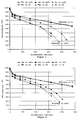
- FIGS. 1 to 3 The current-voltage curves of such a membrane fuel cell in air and oxygen operation are shown in FIGS. 1 to 3.
- Comparative Example 1 The coating dispersion of Comparative Example 1 was sprayed onto the Nafion® 117 membrane based on Protocol II from US Pat. No. 5,211,984.
- the spraying process was carried out using a template in order to obtain an electrode of the required size. This process can be repeated several times after the electrode has dried briefly. After the first electrode had completely dried after about 20 minutes at a temperature of 150 ° C., the counter electrode was applied in accordance with the same procedure.
- the back protonation was carried out in 1 N sulfuric acid.
- the current-voltage curves of this cell are shown in FIGS. 1 to 3 for air and oxygen operation.
- the total porosity of the electrodes produced in this way was 35%, their layer thickness 10 ⁇ m and their Pt concentration 0.15 mg Pt / cm 2 .
- the finished electrodes had a thickness of approximately 5 ⁇ m, a total porosity of 40% and a platinum loading of 0.15 mg Pt / cm 2 .
- the current-voltage curves of this EME unit are shown in Figure 4.
- a mixture of catalyst (20% by weight Pt on carbon black Vulcan® XC 72), ionomer solution, glycerol and a 20% solution of tetrabutylammonium hydroxide (TBAOH) in water was prepared.
- the paste was concentrated in a forced-air drying cabinet at 40 - 50 ° C. Then Li 2 CO 3 was added and stirred in. The mixture was dispersed using a three-roll mill. The resulting paste had the following composition: catalyst 7.67% Nafion (polymer) 2.56% Li 2 CO 3 2.6% TBAOH 1 % Glycerin 63.85% Alcohols, water 22.32%
- the viscosity of the paste was 1.86 Pas at a shear rate of 100 / s.
- the paste was printed through a VA steel sieve (80 mesh, 150 ⁇ m emulsion thickness, sieve cut area 5 cm ⁇ 5 cm) onto a Nafion 117 membrane in Na + form and dried at 140 ° C. This procedure was Repeated until a platinum load of 0.15 mg / cm 2 was reached. The back of the membrane was then made in the same way.
- the protonation and decomposition of the Li 2 CO 3 was carried out in 1 N sulfuric acid.
- the finished electrodes had a porosity of 31% and a platinum loading of 0.15 mgPt / cm 2 .
- a coating dispersion composed of 3.1% by weight of Pt / C catalyst (30% Pt), 30.9% by weight of a 5% ionomer solution in 90% by weight was used.
- the back protonation and the decomposition of the Li 2 CO 3 takes place in 1 N sulfuric acid.
- the current-voltage curves of this cell which show higher cell voltages and reduced mass transfer resistances as well as a significantly improved catalyst usage in air, are shown in FIG. 1.
- the total porosity of the electrode produced in this way was 65%.
- the platinum concentration was the same as that of the comparative examples.
- the average layer thickness was 15 - 20 ⁇ m.
- Example 2 Another electrode-membrane unit was produced as described in Example 1. In contrast to Example 1, 1.5% by weight ammonium oxalate was used as the pore former.
- the pore former was decomposed after the electrode had dried by raising the temperature of the membrane to 180 ° C. for 5 minutes.
- the subsequent back protonation was carried out as in Example 1 in 1 N sulfuric acid.
- the total porosity of the electrode produced in this way was 48%.
- Layer thickness and platinum concentration were the same as in Example 1.
- Example 2 Another electrode-membrane unit was produced as described in Example 1. In contrast to Example 1, 1.5% by weight ammonium carbonate was used as the pore former.
- the current-voltage curves of the electrode-membrane units produced in the above examples were recorded in a quasi-stationary galvanostatic manner.
- the EME units were covered on both sides with graphite paper as a gas distributor and current collector and in a graphite cell block clamped.
- the effective electrode area was 25 cm 2 .
- the cell temperature was kept constant at 75 ° C during the measurements.
- the anode-side hydrogen flow was 300 ml / min at a pressure of 1 bar and was moistened with water vapor in accordance with the equilibrium vapor pressure at 85 ° C.
- the cell On the cathode side, the cell was supplied with dry air or pure oxygen with a volume flow of 300 ml / min or 150 ml / min.
- Figures 1 to 4 each show the measured current-voltage curves of the electrode-membrane units according to the invention of Examples 1 to 3 (B1, B2, B3) in comparison to the current-voltage curves of the electrode-membrane units of Comparative Examples 1 to 4 (VB1, VB2, VB3, VB4).
- the electrode-membrane units according to the invention show significantly improved performance data in air operation. This also applies to comparative examples 3 and 4, both of which were produced using pore formers in the coating dispersion in a hot press process (VB3) and in a screen printing process (VB4).
Landscapes
- Chemical & Material Sciences (AREA)
- Chemical Kinetics & Catalysis (AREA)
- Electrochemistry (AREA)
- General Chemical & Material Sciences (AREA)
- Engineering & Computer Science (AREA)
- Materials Engineering (AREA)
- Life Sciences & Earth Sciences (AREA)
- Manufacturing & Machinery (AREA)
- Sustainable Development (AREA)
- Sustainable Energy (AREA)
- Inert Electrodes (AREA)
- Fuel Cell (AREA)
Applications Claiming Priority (2)
| Application Number | Priority Date | Filing Date | Title |
|---|---|---|---|
| DE19611510 | 1996-03-23 | ||
| DE19611510A DE19611510A1 (de) | 1996-03-23 | 1996-03-23 | Gasdiffusionselektrode für Membranbrennstoffzellen und Verfahren zu ihrer Herstellung |
Publications (3)
| Publication Number | Publication Date |
|---|---|
| EP0797265A2 true EP0797265A2 (fr) | 1997-09-24 |
| EP0797265A3 EP0797265A3 (fr) | 2000-07-26 |
| EP0797265B1 EP0797265B1 (fr) | 2004-12-22 |
Family
ID=7789190
Family Applications (1)
| Application Number | Title | Priority Date | Filing Date |
|---|---|---|---|
| EP97104134A Expired - Lifetime EP0797265B1 (fr) | 1996-03-23 | 1997-03-12 | Electrode à diffusion gazeuse pour piles à combustible à membrane et méthode de fabrication |
Country Status (4)
| Country | Link |
|---|---|
| US (1) | US5861222A (fr) |
| EP (1) | EP0797265B1 (fr) |
| JP (1) | JP4056578B2 (fr) |
| DE (2) | DE19611510A1 (fr) |
Cited By (8)
| Publication number | Priority date | Publication date | Assignee | Title |
|---|---|---|---|---|
| WO2002015303A1 (fr) * | 2000-08-16 | 2002-02-21 | Matsushita Electric Industrial Co., Ltd. | Pile a combustible |
| WO2002027821A3 (fr) * | 2000-09-27 | 2002-10-17 | Proton Energy Sys Inc | Composition de catalyseur d'electrode, electrode et assemblage d'electrode de membrane pour piles electrochimiques |
| WO2002080297A3 (fr) * | 2001-03-30 | 2003-02-20 | Creavis Tech & Innovation Gmbh | Membrane electrolytique, unites d'electrodes membranaires les contenant, procedes permettant de les produire et leurs utilisations particulieres |
| US6531240B1 (en) | 1999-03-16 | 2003-03-11 | Johnson Matthey Public Limited Company | Gas diffusion substrates |
| EP0945910A3 (fr) * | 1998-03-23 | 2004-01-07 | Umicore AG & Co. KG | Assemblage membrane-électrode pour des piles à combustible à électrolyte polymère et son procédé de fabrication |
| WO2004032263A3 (fr) * | 2002-09-27 | 2005-02-17 | Bayer Materialscience Ag | Procede de production d'une electrode a diffusion de gaz |
| US7419740B2 (en) | 2000-07-29 | 2008-09-02 | Unicore Ag & Co. Kg | Membrane electrode unit for polymer electrolyte fuel cells and a process for the production thereof |
| EP2398101A1 (fr) | 2010-06-17 | 2011-12-21 | Bayer MaterialScience AG | Electrode de diffusion gazeuse et méthode de fabrication |
Families Citing this family (86)
| Publication number | Priority date | Publication date | Assignee | Title |
|---|---|---|---|---|
| DE19721437A1 (de) * | 1997-05-21 | 1998-11-26 | Degussa | CO-toleranter Anodenkatalysator für PEM-Brennstoffzellen und Verfahren zu seiner Herstellung |
| DE19745904A1 (de) * | 1997-10-17 | 1999-04-22 | Hoechst Ag | Polymerstabilisierte Metallkolloid-Lösungen, Verfahren zu ihrer Herstellung und ihre Verwendung als Katalysatoren für Brennstoffzellen |
| JP3929146B2 (ja) * | 1997-11-07 | 2007-06-13 | 松下電器産業株式会社 | 固体高分子型燃料電池システム |
| US6297185B1 (en) * | 1998-02-23 | 2001-10-02 | T/J Technologies, Inc. | Catalyst |
| US6306536B1 (en) * | 1998-03-27 | 2001-10-23 | Ballard Power Systems Inc. | Method of reducing fuel cell performance degradation of an electrode comprising porous components |
| DE19837669A1 (de) * | 1998-08-20 | 2000-03-09 | Degussa | Katalysatorschicht für Polymer-Elektrolyt-Brennstoffzellen |
| JP4780814B2 (ja) * | 1998-12-15 | 2011-09-28 | 三洋電機株式会社 | 燃料電池 |
| JP3320707B2 (ja) * | 1999-01-27 | 2002-09-03 | 誠一 丸元 | 超高密度植物垂直ミスト水耕システム及び育成パネル |
| DE19910773A1 (de) * | 1999-03-11 | 2000-09-28 | Degussa | Verfahren zum Aufbringen von Elektrodenschichten auf eine bandförmige Polymerelektrolytmembran für Brennstoffzellen |
| US6403245B1 (en) * | 1999-05-21 | 2002-06-11 | Microcoating Technologies, Inc. | Materials and processes for providing fuel cells and active membranes |
| EP1078959B1 (fr) * | 1999-08-27 | 2002-03-13 | Degussa AG | Noir de carbone, procédé pour sa préparation et son utilisation |
| DE19951936A1 (de) | 1999-10-28 | 2001-05-10 | Forschungszentrum Juelich Gmbh | Herstellung von Katalysatorschichten auf Membranen für Niedertemperatur-Brennstoffzellen |
| EP1232533A2 (fr) | 1999-11-17 | 2002-08-21 | Neah Power Systems, Inc. | Piles a combustible ayant des substrats de silicium et/ou des structures de soutien derivees de sol-gel |
| AU2001227022A1 (en) * | 2000-01-18 | 2001-07-31 | Ramot University Authority For Applied Research And Industrial Development Ltd. | Fuel cell with proton conducting membrane |
| US6447943B1 (en) * | 2000-01-18 | 2002-09-10 | Ramot University Authority For Applied Research & Industrial Development Ltd. | Fuel cell with proton conducting membrane with a pore size less than 30 nm |
| US6828054B2 (en) | 2000-02-11 | 2004-12-07 | The Texas A&M University System | Electronically conducting fuel cell component with directly bonded layers and method for making the same |
| US6770394B2 (en) | 2000-02-11 | 2004-08-03 | The Texas A&M University System | Fuel cell with monolithic flow field-bipolar plate assembly and method for making and cooling a fuel cell stack |
| DK1150369T3 (da) | 2000-04-28 | 2003-10-13 | Omg Ag & Co Kg | Gasfordelingsstrukturer og gasdiffusionselektroder til polymerelektrolyt-brændstofceller |
| DE10037074A1 (de) | 2000-07-29 | 2002-02-14 | Omg Ag & Co Kg | Tinte zur Herstellung von Membran-Elektroden-Einheiten für PEM-Brennstoffzellen |
| DE10037071A1 (de) * | 2000-07-29 | 2002-02-21 | Omg Ag & Co Kg | Edelmetall-Nanopartikel, Verfahren zu ihrer Herstellung und Verwendung |
| TW525314B (en) * | 2000-09-29 | 2003-03-21 | Sony Corp | Fuel cell and method for preparation thereof |
| DE10050467A1 (de) * | 2000-10-12 | 2002-05-16 | Omg Ag & Co Kg | Verfahren zur Herstellung einer Membran-Elektrodeneinheit für Brennstoffzellen |
| US6696382B1 (en) | 2000-11-14 | 2004-02-24 | The Regents Of The University Of California | Catalyst inks and method of application for direct methanol fuel cells |
| US20030091891A1 (en) * | 2001-01-16 | 2003-05-15 | Tomoaki Yoshida | Catalyst composition for cell, gas diffusion layer, and fuel cell comprising the same |
| EP1254712B1 (fr) * | 2001-05-05 | 2005-07-20 | Umicore AG & Co. KG | Catalyseur supporté à base de métal noble et son procédé de préparation |
| EP1254711A1 (fr) * | 2001-05-05 | 2002-11-06 | OMG AG & Co. KG | Catalyseur supporté à base de métal noble et son procédé de préparation |
| DE10130441B4 (de) * | 2001-06-23 | 2005-01-05 | Uhde Gmbh | Verfahren zum Herstellen von Gasdiffusionselektroden |
| US6667756B2 (en) * | 2001-08-27 | 2003-12-23 | Xerox Corporation | Method of shifting an image or paper to reduce show through in duplex printing |
| CA2407202C (fr) * | 2001-10-11 | 2009-11-03 | Honda Giken Kogyo Kabushiki Kaisha | Electrode pour pile a combustible a electrolyte polymere |
| US6686308B2 (en) * | 2001-12-03 | 2004-02-03 | 3M Innovative Properties Company | Supported nanoparticle catalyst |
| EP1523783A2 (fr) * | 2002-02-28 | 2005-04-20 | Häring, Thomas | Structures en couches et leur procede de production |
| EP1387423B1 (fr) * | 2002-07-31 | 2009-01-21 | Umicore AG & Co. KG | Encres aqueuses catalytiques et leurs emplois dans la fabrication de substrats recouverts de catalyseur |
| JP3891484B2 (ja) * | 2002-09-05 | 2007-03-14 | 株式会社ノリタケカンパニーリミテド | 電解質膜およびその膜を備えた燃料電池 |
| US6695986B1 (en) | 2002-09-25 | 2004-02-24 | The United States Of America As Represented By The Secretary Of The Navy | Electrocatalytic enhancement with catalyst-modified carbon-silica composite aerogels |
| US20040107869A1 (en) * | 2002-12-10 | 2004-06-10 | 3M Innovative Properties Company | Catalyst ink |
| EP1654776B1 (fr) * | 2003-07-14 | 2013-09-11 | Umicore AG & Co. KG | Unité membrane-électrode pour des installation électrochmiques |
| US20050014056A1 (en) * | 2003-07-14 | 2005-01-20 | Umicore Ag & Co. Kg | Membrane electrode unit for electrochemical equipment |
| TWI274084B (en) | 2003-08-05 | 2007-02-21 | Lg Chemical Ltd | Hybrid membrane-electrode assembly with minimal interfacial resistance and preparation method thereof |
| JP4870328B2 (ja) * | 2003-10-10 | 2012-02-08 | ペルメレック電極株式会社 | 膜―電極接合体の製造方法 |
| CN1874841B (zh) * | 2003-10-29 | 2010-09-15 | 尤米科尔股份公司及两合公司 | 水电解用贵金属氧化物催化剂 |
| DE102004024845A1 (de) * | 2004-05-13 | 2005-12-08 | Volkswagen Ag | Verfahren zur Herstellung einer Katalysatorschicht für elektrochemische Zellen |
| DE102004024844A1 (de) * | 2004-05-13 | 2005-12-08 | Volkswagen Ag | Elektrodenpaste zur Herstellung einer Katalysatorschicht für eine elektrochemische Zelle sowie Verfahren zur Herstellung einer Katalysatorschicht |
| CN100405641C (zh) * | 2004-06-23 | 2008-07-23 | 比亚迪股份有限公司 | 质子交换膜燃料电池膜电极的制备方法 |
| US20080020253A1 (en) * | 2004-07-09 | 2008-01-24 | Ingo Neubert | Method for Producing a Membrane-Electrode Unit |
| US7422994B2 (en) * | 2005-01-05 | 2008-09-09 | Symyx Technologies, Inc. | Platinum-copper-tungsten fuel cell catalyst |
| JP2008534719A (ja) | 2005-03-30 | 2008-08-28 | ユミコア・アクチエンゲゼルシャフト・ウント・コムパニー・コマンディットゲゼルシャフト | 触媒層を製造するためのインク |
| GB0510119D0 (en) * | 2005-05-18 | 2005-06-22 | Johnson Matthey Plc | Polymer dispersion and electrocatalyst ink |
| JP4233051B2 (ja) * | 2005-09-30 | 2009-03-04 | 本田技研工業株式会社 | 燃料電池用電極層の製造方法 |
| US20080280190A1 (en) * | 2005-10-20 | 2008-11-13 | Robert Brian Dopp | Electrochemical catalysts |
| US20070092784A1 (en) * | 2005-10-20 | 2007-04-26 | Dopp Robert B | Gas diffusion cathode using nanometer sized particles of transition metals for catalysis |
| US20070227300A1 (en) * | 2006-03-31 | 2007-10-04 | Quantumsphere, Inc. | Compositions of nanometal particles containing a metal or alloy and platinum particles for use in fuel cells |
| US7955755B2 (en) | 2006-03-31 | 2011-06-07 | Quantumsphere, Inc. | Compositions of nanometal particles containing a metal or alloy and platinum particles |
| US7785748B2 (en) * | 2006-04-03 | 2010-08-31 | University Of Delaware | Nano-based gas diffusion media |
| US20090215615A1 (en) * | 2006-07-11 | 2009-08-27 | 3M Innovative Properties Company | Method of forming supported nanoparticle catalysts |
| JP5011867B2 (ja) * | 2006-07-21 | 2012-08-29 | トヨタ自動車株式会社 | 燃料電池用の膜電極接合体の製造方法 |
| US8383293B2 (en) * | 2006-11-22 | 2013-02-26 | GM Global Technology Operations LLC | Supports for fuel cell catalysts based on transition metal silicides |
| JP4661825B2 (ja) * | 2007-05-09 | 2011-03-30 | トヨタ自動車株式会社 | 触媒粉体生成方法 |
| KR100874112B1 (ko) * | 2007-06-25 | 2008-12-15 | 한화석유화학 주식회사 | 연료전지용 촉매 잉크 및 이를 이용한 막-전극 복합체의제조방법 |
| DE102007031526B4 (de) * | 2007-07-06 | 2010-07-08 | Fraunhofer-Gesellschaft zur Förderung der angewandten Forschung e.V. | Verwendung einer Anode in einer Brennstoffzelle zur Oxidation von Ethanol und/oder zumindest eines C3 bis C10-haltigen Alkohols |
| US20090042091A1 (en) | 2007-08-09 | 2009-02-12 | Matsushita Electric Industrial Co., Ltd. | Supported catalyst layers for direct oxidation fuel cells |
| WO2009089018A2 (fr) | 2008-01-08 | 2009-07-16 | Sion Power Corporation | Electrodes poreuses et procédés associés |
| TWI459622B (zh) * | 2007-11-15 | 2014-11-01 | Atomic Energy Council | Preparation of Thin Film Fuel Cell Electrode Using Nano Carbide Carrier Catalyst by Low Voltage Electrophoresis |
| KR20090058406A (ko) * | 2007-12-04 | 2009-06-09 | 한화석유화학 주식회사 | 연료전지용 독립 전극 촉매 층 및 이를 이용한 막-전극접합체의 제조방법 |
| US8501366B1 (en) | 2008-06-30 | 2013-08-06 | Sandia Corporation | Nanoengineered membrane electrode assembly interface |
| JP5277770B2 (ja) * | 2008-07-23 | 2013-08-28 | トヨタ自動車株式会社 | 固体高分子型燃料電池用膜電極接合体の製造方法、固体高分子型燃料電池用膜電極接合体、及び固体高分子型燃料電池 |
| JP5376217B2 (ja) * | 2009-02-13 | 2013-12-25 | 株式会社Gsユアサ | 燃料電池の電極材料用の粒子の製造方法、燃料電池用電極材料およびその製造方法、ならびに、燃料電池用電極の製造方法 |
| US20110206992A1 (en) * | 2009-08-28 | 2011-08-25 | Sion Power Corporation | Porous structures for energy storage devices |
| WO2011031297A2 (fr) * | 2009-08-28 | 2011-03-17 | Sion Power Corporation | Cellules électrochimiques comprenant des structures poreuses comprenant du soufre |
| JP5565305B2 (ja) * | 2010-01-07 | 2014-08-06 | 株式会社エクォス・リサーチ | 燃料電池用触媒層の製造装置、燃料電池用触媒層の製造方法、高分子電解質溶液及び高分子電解質溶液の製造方法 |
| WO2011083842A1 (fr) * | 2010-01-07 | 2011-07-14 | 株式会社エクォス・リサーチ | Appareil pour la production de couche catalytique pour une pile à combustible, procédé de production d'une couche catalytique pour pile à combustible, solution polyélectrolyte et procédé de production de solution polyélectrolyte |
| JP5174128B2 (ja) * | 2010-11-15 | 2013-04-03 | 三洋電機株式会社 | ガス拡散層、燃料電池用電極及び燃料電池 |
| EP2729979B1 (fr) * | 2011-07-08 | 2017-12-13 | Audi AG | Électrode à faible charge de platine |
| EP2608297A1 (fr) | 2011-12-22 | 2013-06-26 | Umicore AG & Co. KG | Catalyseur d'oxyde métallique précieux pour électrolyse de l'eau |
| KR20130123189A (ko) * | 2012-05-02 | 2013-11-12 | 삼성전자주식회사 | 고체산화물 연료전지용 음극 지지체 및 그 제조방법과 이를 포함한 고체산화물 연료전지 |
| CN104321916B (zh) | 2012-05-31 | 2017-05-17 | 京瓷株式会社 | 电池单元及电池堆装置以及电化学模块、电化学装置 |
| KR101991149B1 (ko) | 2012-12-19 | 2019-06-19 | 시온 파워 코퍼레이션 | 전극 구조물 및 그의 제조 방법 |
| KR102092943B1 (ko) * | 2014-01-29 | 2020-04-14 | 삼성전자주식회사 | 전기 흡착 탈이온 장치용 전극 조성물, 및 이를 포함하는 전기 흡착 탈이온 장치용 전극 |
| KR102622781B1 (ko) | 2014-05-01 | 2024-01-08 | 시온 파워 코퍼레이션 | 전극 제조 방법 및 관련 제품 |
| US10629935B2 (en) | 2014-10-24 | 2020-04-21 | Mitsui Mining & Smelting Co., Ltd. | Fuel cell electrode catalyst layer, production method therefor, membrane electrode assembly, and solid polymer fuel cell |
| EP3379627B1 (fr) * | 2015-11-19 | 2023-03-08 | Panasonic Intellectual Property Management Co., Ltd. | Couche de diffusion gazeuse pour pile à combustible, procédé de fabrication de ladite couche, ensemble membrane-électrode et pile à combustible |
| DE102018204369A1 (de) * | 2018-03-22 | 2019-09-26 | Audi Ag | Verfahren zur Herstellung einer Elektrode mit erhöhter Porosität und eine entsprechende Elektrode |
| KR102881926B1 (ko) * | 2019-11-26 | 2025-11-05 | 현대자동차주식회사 | 연료전지용 촉매 슬러리 및 이의 제조방법 |
| CN111082072B (zh) * | 2019-12-31 | 2022-01-11 | 上海神力科技有限公司 | 一种燃料电池用气体扩散层及其制备方法 |
| CN114236006B (zh) * | 2021-12-17 | 2024-06-18 | 河南省商业科学研究所有限责任公司 | 一种检测动物尿液中瘦肉精的方法 |
| CN114236005B (zh) * | 2021-12-17 | 2024-06-21 | 河南省商业科学研究所有限责任公司 | 一种检测动物性食品中瘦肉精的方法 |
| DE102024204388A1 (de) * | 2024-05-13 | 2025-11-13 | Siemens Energy Global GmbH & Co. KG | Verfahren zur Herstellung einer Gasdiffusionselektrode für eine elektrochemische Zelle, Gasdiffusionselektrode sowie Elektrolysezelle mit einer Gasdiffusionselektrode |
Family Cites Families (19)
| Publication number | Priority date | Publication date | Assignee | Title |
|---|---|---|---|---|
| US3385780A (en) * | 1964-07-10 | 1968-05-28 | Exxon Research Engineering Co | Porous dual structure electrode |
| CH647004A5 (en) * | 1981-05-27 | 1984-12-28 | Bbc Brown Boveri & Cie | Method for coating a solid electrolyte present in the form of a sheet |
| US4469579A (en) * | 1981-06-26 | 1984-09-04 | Diamond Shamrock Corporation | Solid polymer electrolytes and electrode bonded with hydrophylic fluorocopolymers |
| NL8301780A (nl) * | 1983-05-19 | 1984-12-17 | Electrochem Energieconversie | Poreuze elektrode. |
| US4581116A (en) * | 1984-12-04 | 1986-04-08 | The Dow Chemical Company | Gas diffusion composite electrode having novel hydrophilic layer |
| AT389020B (de) * | 1986-08-08 | 1989-10-10 | Peter Dipl Ing Dr Schuetz | Brennstoffzelle |
| US4876115A (en) * | 1987-01-30 | 1989-10-24 | United States Department Of Energy | Electrode assembly for use in a solid polymer electrolyte fuel cell |
| US5211984A (en) * | 1991-02-19 | 1993-05-18 | The Regents Of The University Of California | Membrane catalyst layer for fuel cells |
| JP3245929B2 (ja) * | 1992-03-09 | 2002-01-15 | 株式会社日立製作所 | 燃料電池及びその応用装置 |
| US5272017A (en) * | 1992-04-03 | 1993-12-21 | General Motors Corporation | Membrane-electrode assemblies for electrochemical cells |
| US5399184A (en) * | 1992-05-01 | 1995-03-21 | Chlorine Engineers Corp., Ltd. | Method for fabricating gas diffusion electrode assembly for fuel cells |
| DE4241150C1 (de) * | 1992-12-07 | 1994-06-01 | Fraunhofer Ges Forschung | Elektrodenmembran-Verbund, Verfahren zu dessen Herstellung sowie dessen Verwendung |
| US5330860A (en) * | 1993-04-26 | 1994-07-19 | E. I. Du Pont De Nemours And Company | Membrane and electrode structure |
| US5470448A (en) * | 1994-01-28 | 1995-11-28 | United Technologies Corporation | High performance electrolytic cell electrode/membrane structures and a process for preparing such electrode structures |
| DE4426973C1 (de) * | 1994-07-29 | 1996-03-28 | Degussa | Verfahren zur Herstellung eines als Brennstoffzellenelektrode einsetzbaren Plattinlegierungskatalysators |
| US5523177A (en) * | 1994-10-12 | 1996-06-04 | Giner, Inc. | Membrane-electrode assembly for a direct methanol fuel cell |
| US6054230A (en) * | 1994-12-07 | 2000-04-25 | Japan Gore-Tex, Inc. | Ion exchange and electrode assembly for an electrochemical cell |
| ATE245852T1 (de) * | 1995-10-06 | 2003-08-15 | Dow Global Technologies Inc | Fluessigkeitsverteilungsstrukturen fuer membran- elektrode-anordnungen von brennstoffzellen |
| JPH09199138A (ja) * | 1996-01-19 | 1997-07-31 | Toyota Motor Corp | 燃料電池用の電極または電極・電解質膜接合体の製造方法および燃料電池用の電極 |
-
1996
- 1996-03-23 DE DE19611510A patent/DE19611510A1/de not_active Ceased
-
1997
- 1997-03-12 DE DE59712123T patent/DE59712123D1/de not_active Expired - Lifetime
- 1997-03-12 EP EP97104134A patent/EP0797265B1/fr not_active Expired - Lifetime
- 1997-03-21 JP JP06713297A patent/JP4056578B2/ja not_active Expired - Fee Related
- 1997-03-24 US US08/822,864 patent/US5861222A/en not_active Expired - Lifetime
Cited By (12)
| Publication number | Priority date | Publication date | Assignee | Title |
|---|---|---|---|---|
| EP0945910A3 (fr) * | 1998-03-23 | 2004-01-07 | Umicore AG & Co. KG | Assemblage membrane-électrode pour des piles à combustible à électrolyte polymère et son procédé de fabrication |
| US6531240B1 (en) | 1999-03-16 | 2003-03-11 | Johnson Matthey Public Limited Company | Gas diffusion substrates |
| US7419740B2 (en) | 2000-07-29 | 2008-09-02 | Unicore Ag & Co. Kg | Membrane electrode unit for polymer electrolyte fuel cells and a process for the production thereof |
| WO2002015303A1 (fr) * | 2000-08-16 | 2002-02-21 | Matsushita Electric Industrial Co., Ltd. | Pile a combustible |
| EP1320140A4 (fr) * | 2000-08-16 | 2007-10-10 | Matsushita Electric Industrial Co Ltd | Pile a combustible |
| WO2002027821A3 (fr) * | 2000-09-27 | 2002-10-17 | Proton Energy Sys Inc | Composition de catalyseur d'electrode, electrode et assemblage d'electrode de membrane pour piles electrochimiques |
| US6828056B2 (en) | 2000-09-27 | 2004-12-07 | Proton Energy Systems, Inc. | Electrode catalyst composition, electrode, and membrane electrode assembly for electrochemical cells |
| WO2002080297A3 (fr) * | 2001-03-30 | 2003-02-20 | Creavis Tech & Innovation Gmbh | Membrane electrolytique, unites d'electrodes membranaires les contenant, procedes permettant de les produire et leurs utilisations particulieres |
| WO2004032263A3 (fr) * | 2002-09-27 | 2005-02-17 | Bayer Materialscience Ag | Procede de production d'une electrode a diffusion de gaz |
| EP2398101A1 (fr) | 2010-06-17 | 2011-12-21 | Bayer MaterialScience AG | Electrode de diffusion gazeuse et méthode de fabrication |
| DE102010030203A1 (de) | 2010-06-17 | 2011-12-22 | Bayer Materialscience Ag | Gasdiffusionselektrode und Verfahren zu ihrer Herstellung |
| US10224552B2 (en) | 2010-06-17 | 2019-03-05 | Covestro Ag | Gas diffusion electrode and process for production thereof |
Also Published As
| Publication number | Publication date |
|---|---|
| EP0797265A3 (fr) | 2000-07-26 |
| EP0797265B1 (fr) | 2004-12-22 |
| US5861222A (en) | 1999-01-19 |
| JP4056578B2 (ja) | 2008-03-05 |
| DE19611510A1 (de) | 1997-09-25 |
| JPH103929A (ja) | 1998-01-06 |
| DE59712123D1 (de) | 2005-01-27 |
Similar Documents
| Publication | Publication Date | Title |
|---|---|---|
| EP0797265B1 (fr) | Electrode à diffusion gazeuse pour piles à combustible à membrane et méthode de fabrication | |
| EP1150369B1 (fr) | Structures de distributeurs de gaz et électrodes à diffusion gazeuze pour des piles à combustible | |
| EP1198021B1 (fr) | Procédé de fabrication d'une unité membrane-électrodes pour piles à combustible | |
| EP1176653B1 (fr) | Unité d'électrodes-membrane pour piles à combustible à électrolyte polymère et son procédé de fabrication | |
| DE19812592B4 (de) | Membran-Elektroden-Einheit für Polymer-Elektrolyt-Brennstoffzellen, Verfahren zu ihrer Herstellung sowie Tinte | |
| EP1261057B1 (fr) | Procédé de fabrication d'une unité membrane-électrode et unité membrane-élecrote obtenue par ce procédé | |
| DE10007990B4 (de) | Verfahren zum Herstellen eines Elektrodenaufbaus und eines kombinierten Elektrolyt- und Elektrodenaufbaus sowie ein Elektrodenaufbau und ein kombinierter Elektrolyt- und Elektrodenaufbau für elektrochemische Zellen | |
| DE69829933T2 (de) | Elektrode aus Festpolymerelektrolyt-Katalysator Kompositen, Elektrode für Brennstoffzellen und Verfahren zur Herstellung dieser Elektroden | |
| EP0987777B1 (fr) | Couche catalytique pour des électrodes polymériques des piles à combustible | |
| DE69613030T2 (de) | Material zur Verwendung bei der Herstellung von katalytischen Elektroden | |
| DE19958959B4 (de) | Brennstoffzellenelektrode und Verfahren zur Herstellung einer Brennstoffzellenelektrode | |
| DE112013007069B4 (de) | Verfahren zum Herstellen eines feinen Katalysatorpartikels und Brennstoffzelle umfassend ein durch das Herstellverfahren hergestelltes feines Katalysatorpartikel | |
| DE10151458A1 (de) | Verfahren zur Herstellung von Membranelektrolytbaugruppen | |
| DE10159476A1 (de) | Verfahren zur Herstellung von Membran-Elektrodeneinheiten für Brennstoffzellen | |
| DE112004002061T5 (de) | Verfahren zur Herstellung von Membranen und Membranelektrodenanordnungen mit einem Wasserstoffperoxid-zersetzungskatalysator | |
| WO2022078872A1 (fr) | Membrane à revêtement catalytique et cellule d'électrolyse de l'eau | |
| WO2000013243A2 (fr) | Amelioration apportee a une electrode a diffusion gazeuse, procede de production correspondant et procede pour rendre hydrophobe une electrode a diffusion gazeuse | |
| DE10247452B4 (de) | Elektrode für Polymerelektrolyt-Brennstoffzelle | |
| WO2015139791A1 (fr) | Couche de catalyseur pour une pile à combustible et procédé de fabrication de cette couche | |
| DE19701174A1 (de) | Verfahren zur Messung der für eine Reaktion verfügbaren spezifischen Oberflächengröße eines Edelmetall-Katalysators in der Elektrode einer Polymer-Elektrolyt-Membran-Brennstoffzelle und zur Bemessung der Katalysatorschicht für die Elektrode dieser Brennstoffzelle | |
| DE112020001053T5 (de) | Kathodenkatalysatorschicht für eine Brennstoffzelle, und Brennstoffzelle | |
| DE602004010021T2 (de) | Tinte zur Herstellung einer Katalysatorschicht, Elektrode und Membran-Elektrode-Anordnung in denen solche Tinte verwendet wird | |
| EP1601037B1 (fr) | Membrane-électrode-assemblage pour pile à combustible à alimentation directe en méthanole (DMFC) | |
| DE10052189B4 (de) | Mehrschichtige Gasdiffusionselektrode einer Polymerelektrolytmembran-Brennstoffzelle, Membranelektrodenanordnung, Verfahren zur Herstellung einer Gasdiffusionselektrode und einer Membranelektrodenanordnung sowie Verwendung der Membranelektrodenanordnung | |
| EP1150370A2 (fr) | Structures de distribuition de gaz et électrodes à diffusion gazeuse pour piles à combustible avec un électrolyte polymérique |
Legal Events
| Date | Code | Title | Description |
|---|---|---|---|
| PUAI | Public reference made under article 153(3) epc to a published international application that has entered the european phase |
Free format text: ORIGINAL CODE: 0009012 |
|
| AK | Designated contracting states |
Kind code of ref document: A2 Designated state(s): DE FR GB IT NL |
|
| RAP1 | Party data changed (applicant data changed or rights of an application transferred) |
Owner name: DEGUSSA-HUELS AKTIENGESELLSCHAFT |
|
| RAP3 | Party data changed (applicant data changed or rights of an application transferred) |
Owner name: DEGUSSA-HUELS AKTIENGESELLSCHAFT |
|
| PUAL | Search report despatched |
Free format text: ORIGINAL CODE: 0009013 |
|
| AK | Designated contracting states |
Kind code of ref document: A3 Designated state(s): DE FR GB IT NL |
|
| 17P | Request for examination filed |
Effective date: 20000623 |
|
| RAP1 | Party data changed (applicant data changed or rights of an application transferred) |
Owner name: DMC2 DEGUSSA METALS CATALYSTS CERDEC AG |
|
| 17Q | First examination report despatched |
Effective date: 20010328 |
|
| RAP1 | Party data changed (applicant data changed or rights of an application transferred) |
Owner name: OMG AG & CO. KG |
|
| RAP1 | Party data changed (applicant data changed or rights of an application transferred) |
Owner name: UMICORE AG & CO. KG |
|
| GRAP | Despatch of communication of intention to grant a patent |
Free format text: ORIGINAL CODE: EPIDOSNIGR1 |
|
| GRAS | Grant fee paid |
Free format text: ORIGINAL CODE: EPIDOSNIGR3 |
|
| GRAA | (expected) grant |
Free format text: ORIGINAL CODE: 0009210 |
|
| AK | Designated contracting states |
Kind code of ref document: B1 Designated state(s): DE FR GB IT NL |
|
| REG | Reference to a national code |
Ref country code: GB Ref legal event code: FG4D Free format text: NOT ENGLISH |
|
| REF | Corresponds to: |
Ref document number: 59712123 Country of ref document: DE Date of ref document: 20050127 Kind code of ref document: P |
|
| GBT | Gb: translation of ep patent filed (gb section 77(6)(a)/1977) |
Effective date: 20050405 |
|
| PLBE | No opposition filed within time limit |
Free format text: ORIGINAL CODE: 0009261 |
|
| STAA | Information on the status of an ep patent application or granted ep patent |
Free format text: STATUS: NO OPPOSITION FILED WITHIN TIME LIMIT |
|
| 26N | No opposition filed |
Effective date: 20050923 |
|
| ET | Fr: translation filed | ||
| PGFP | Annual fee paid to national office [announced via postgrant information from national office to epo] |
Ref country code: IT Payment date: 20100324 Year of fee payment: 14 Ref country code: FR Payment date: 20100402 Year of fee payment: 14 |
|
| PGFP | Annual fee paid to national office [announced via postgrant information from national office to epo] |
Ref country code: GB Payment date: 20100322 Year of fee payment: 14 |
|
| PGFP | Annual fee paid to national office [announced via postgrant information from national office to epo] |
Ref country code: NL Payment date: 20100315 Year of fee payment: 14 |
|
| REG | Reference to a national code |
Ref country code: NL Ref legal event code: V1 Effective date: 20111001 |
|
| GBPC | Gb: european patent ceased through non-payment of renewal fee |
Effective date: 20110312 |
|
| REG | Reference to a national code |
Ref country code: FR Ref legal event code: ST Effective date: 20111130 |
|
| PG25 | Lapsed in a contracting state [announced via postgrant information from national office to epo] |
Ref country code: NL Free format text: LAPSE BECAUSE OF NON-PAYMENT OF DUE FEES Effective date: 20111001 Ref country code: FR Free format text: LAPSE BECAUSE OF NON-PAYMENT OF DUE FEES Effective date: 20110331 |
|
| PG25 | Lapsed in a contracting state [announced via postgrant information from national office to epo] |
Ref country code: GB Free format text: LAPSE BECAUSE OF NON-PAYMENT OF DUE FEES Effective date: 20110312 Ref country code: IT Free format text: LAPSE BECAUSE OF NON-PAYMENT OF DUE FEES Effective date: 20110312 |
|
| PGFP | Annual fee paid to national office [announced via postgrant information from national office to epo] |
Ref country code: DE Payment date: 20150305 Year of fee payment: 19 |
|
| REG | Reference to a national code |
Ref country code: DE Ref legal event code: R119 Ref document number: 59712123 Country of ref document: DE |
|
| PG25 | Lapsed in a contracting state [announced via postgrant information from national office to epo] |
Ref country code: DE Free format text: LAPSE BECAUSE OF NON-PAYMENT OF DUE FEES Effective date: 20161001 |