EP0798090A2 - Verfahren zum Schneiden eines Werkstückes mittels einer Drahtsäge - Google Patents
Verfahren zum Schneiden eines Werkstückes mittels einer Drahtsäge Download PDFInfo
- Publication number
- EP0798090A2 EP0798090A2 EP97301965A EP97301965A EP0798090A2 EP 0798090 A2 EP0798090 A2 EP 0798090A2 EP 97301965 A EP97301965 A EP 97301965A EP 97301965 A EP97301965 A EP 97301965A EP 0798090 A2 EP0798090 A2 EP 0798090A2
- Authority
- EP
- European Patent Office
- Prior art keywords
- wire
- workpiece
- slicing
- cutting
- cutting length
- Prior art date
- Legal status (The legal status is an assumption and is not a legal conclusion. Google has not performed a legal analysis and makes no representation as to the accuracy of the status listed.)
- Withdrawn
Links
Images


Classifications
-
- B—PERFORMING OPERATIONS; TRANSPORTING
- B28—WORKING CEMENT, CLAY, OR STONE
- B28D—WORKING STONE OR STONE-LIKE MATERIALS
- B28D5/00—Fine working of gems, jewels, crystals, e.g. of semiconductor material; apparatus or devices therefor
- B28D5/04—Fine working of gems, jewels, crystals, e.g. of semiconductor material; apparatus or devices therefor by tools other than rotary type, e.g. reciprocating tools
- B28D5/045—Fine working of gems, jewels, crystals, e.g. of semiconductor material; apparatus or devices therefor by tools other than rotary type, e.g. reciprocating tools by cutting with wires or closed-loop blades
Definitions
- the present invention relates to a method of cutting a workpiece with a wire saw, for example, for slicing wafers from a semiconductor silicon ingot.
- the cutting length of the workpiece is the length of the cut portion of the workpiece in contact with the wire.
- the cutting length is short at the beginning and end of slicing and is longest when the center portion of the workpiece is cut. Therefore, as shown in FIG.5B, when the wire 1 cuts the central portion of the workpiece, the wire 1 become thinner compared to the case where the wire 1 cuts the upper and lower portions at the beginning and end of slicing. Accordingly, the cutting thickness (the thickness of the removed portion) changes along the cutting direction, so that the sliced wafers W come to have a nonuniform thickness, being thicker in the central part.
- the wafers W of non-uniform thickness require a great amount of lapping in a subsequent lapping stage, which causes greater loss of the material of the workpiece.
- the present invention has been accomplished to solve the above-mentioned problem, and it is an object of the invention to provide a method of slicing a workpiece such as a silicon ingot, which makes it possible to slice the workpiece into a plurality of plates, such as wafers, having a uniform thickness without causing changes in the cutting thickness from the beginning to the end.
- the present invention provides a method of slicing a workpiece in which a cylindrical workpiece is pressed against a moving wire so as to cut out plates having a substantially circular shape. A thinner portion of the wire is used at the beginning of slicing to cut a portion of the workpiece where the cutting length is shorter than a predetermined length, and a thicker portion of the wire is used when the cutting length becomes longer than the predetermined length.
- the present invention also provides a method of slicing a workpiece with a wire saw in which a thinner portion of the wire is used at the end of slicing to cut a portion of the workpiece where the cutting length is shorter than a predetermined length.
- the present invention further provides a method of slicing a workpiece with a wire saw in which a thinner portion of the wire is used at the beginning and end of slicing to cut corresponding portions of the workpiece where the cutting length is shorter than a predetermined length, and a thicker portion of the wire is used to cut the center portion of the workpiece where the cutting length is longer than the predetermined length.
- the cutting length is initially zero and increases to a maximum when the wire cuts the center of the cylinder, then decreases to zero at the end.
- the wear amount of the wire varies in proportion to the cutting length. Therefore, when the cutting length is shorter than a predetermined length, the wear amount of the wire is relatively small and the wire is maintained relatively thick. When the cutting length is longer than the predetermined length, the wear amount of the wire becomes relatively large and the wire becomes relatively thin. As a result, as shown in FIG.
- the cutting thickness becomes relatively large where the wear amount of the wire is relatively small so that the thickness of the circular plate at that portion tends to decrease, whereas the cutting thickness becomes relatively small where the wear amount of the wire is relatively large so that the thickness of the circular plate at that portion tends to increase.
- the portion of the workpiece where the cutting length is shorter than a predetermined length is cut with a thinner portion of the wire, whereas the portion of the workpiece where the cutting length is longer than the predetermined length is cut with a thicker portion of the wire.
- the wire is rewound so as to use a used portion of the wire as the thinner portion for cutting the portion of the workpiece where the cutting length is shorter than the predetermined length.
- the moving direction of the wire is reversed so as to use a used portion of the wire as the thinner portion for cutting the portion of the workpiece where the cutting length is shorter than the predetermined length. Since the used portion of the wire is used again, it is economical.
- the portion of the wire that was used is used again at the beginning and end of slicing, and a new portion of the wire is used when the intermediate region is being cut. This is because the portion of the wire that was used is usually thinner than the new portion of the wire, due to wearing out.
- a portion of a wire that was used for cutting the preceding workpiece may be used either after rewinding, or after reversing the moving direction of the wire. Near the end of slicing, the wire is rewound or the moving direction is reversed, and the used portion of the wire is used again.
- a die may be used for forming the thinner portion of the wire.
- the die may be a roller die including a plurality of rollers.
- the die may be a pulling die having a certain shape of a hole through which a wire material is pulled. The die is used to make a portion of a wire thinner when it is required.
- the thinner portion of the wire is used at the beginning of slicing until the cutting length becomes greater than approximately 50% of the outer diameter of the workpiece.
- the thinner portion of the wire be used near the end of slicing after the cutting length becomes equal to or less than approximately 50% of the outer diameter of the workpiece.
- the cutting length becomes substantially uniform, and the thickness profile of the sliced wafers becomes much more uniform compared with the wafers sliced by the above-described conventional method.
- the cylindrical workpiece is preferably a semiconductor ingot, in particular, a semiconductor silicon ingot.
- the method of slicing with a wire saw according to the present invention may be applied when many wafers W are simultaneously cut out from a silicon ingot G produced, for example, by the single crystal pulling method.
- a steel wire 1 is pulled out from a wire feeder-side X and is spirally wound around three rollers 2, 3, and 4 at a predetermined pitch and pulled out to a wire winder-side Y.
- the wire 1 is moved by the lower roller 2 at a certain linear speed, while a cylindrical ingot G is pressed downward against portions of the wire 1 between the upper rollers 3 and 4, and abrasive grain slurry (oily or water soluble coolant in which fine abrasive grains are suspended) is fed to the areas of contact between the wire 1 and the ingot G.
- abrasive grain slurry oil or water soluble coolant in which fine abrasive grains are suspended
- One method of moving the wire 1 is to simply move the wire 1 in one direction from the wire feeder-side X to the wire winder-side Y.
- Another method is to move the wire 1 reciprocally by reversing the rotational direction of the driving roller 2 periodically such that the wire 1 resultantly advances at a predetermined speed. For example, the wire 1 is moved forward at a predetermined line speed for A seconds, and then moved backward at the same line speed for (A - ⁇ ) seconds, so that the wire 1 is resultantly fed by a distance corresponding to ⁇ seconds every (2A - ⁇ ) seconds.
- the present invention can be applied to both of the above-described cutting methods.
- the cutting method using a wire saw is effective because many wafers are sliced simultaneously, but it has a drawback that the thickness of the wafers are apt to change along the cutting direction, compared with conventional slicing methods such as a method using a slicer with an inner diameter blade.
- One cause of the change in the thickness of the wafer sliced by the wire saw is the change in the wear amount of the wire 1.
- the reason for the change in the wear amount of the wire 1 is as follows.
- the cutting surfaces of the wafer become substantially circular.
- the cutting length T representing the length of contact between the wire 1 and the wafer W changes, so that the wear amount of the wire 1 becomes relatively small where the cutting length is relatively short, whereas the wear amount of the wire 1 becomes relatively large where the cutting length is relatively long.
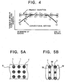
- the diameter of the wire 1 changes in accordance with the wear amount. For example, if various parts of the workpiece were cut by different portions of wire having the same initial diameter, as shown in FIG. 5A (which shows cutting at the upper, center and lower portions), the portions of the wire 1 have different diameter at the end of slicing as shown in FIG. 5B. Specifically, when the wire 1 cut the upper or the lower portions where the cutting length T was relatively short, the diameters of the corresponding portions of the wire 1 did not become thinner so much. In contrast, when the wire 1 cut the central portion where the cutting length T was relatively long, the diameters of the corresponding portions of the wire become thinner much. Therefore, the thickness of the wafers W could not be made uniform.
- the diameter of the wire 1 at the beginning of slicing is changed in accordance with the locations of the ingot G, as shown in FIG. 2A (which shows cutting at the upper, center, and lower portions), so that all the diameters of the corresponding portions of the wire 1 may become the same in the end of slicing, as shown in FIG. 2B.
- a thinner portion of the wire 1 is used where the cutting length T is equal to or smaller than approximately half of the diameter S of the ingot G, and a normal (thicker) diameter portion of the wire 1 is used where the cutting length T is larger than approximately half of the diameter S.
- the thickness of the wafers W becomes substantially uniform, as shown in FIG. 2B.
- the used portion of the wire 1 is reused in order to change the wire diameter.
- part of the used portion of the wire 1 in the wire winder-side Y is rewound to the wire feeder-side X, and the rewound portion of the wire 1 is used at the beginning of slicing of anew ingot G.
- the amount of rewinding is adjusted such that a new portion of the wire is used when the cutting length becomes larger than approximately S/2.
- the wire 1 is moved in the reverse direction and the used portion of the wire is used again.
- the moving direction is simply reversed.
- the reciprocation timing is changed so that the overall moving direction of the wire is reversed.
- the cutting length T becomes S/2 for the first time after the beginning of slicing
- the used portion of the wire 1 is pulled out at a time within a short period of time, and a new portion of the wire 1 is used for slicing.
- the moving direction of the wire is reversed so as to reuse the used portion of the wire 1.
- the used portion of the wire 1 is rewound at a time within a short period of time, and the used portion of the wire 1 is used again.
- a die may be used to reduce the diameter of a portion of a wire 1.
- dies usable in the slicing method include a pulling die with a certain diameter hole and a roller die comprising a pair of rollers with a semi-circular groove in each.
- the ratio of diameter reduction provided by the die is, for example, equal to or less than 2% of the diameter of a new wire.
- FIG. 4 Test results of the above-described cutting are shown in FIG. 4.
- the ordinate represents the thickness of the sliced workpiece and the abscissa represents the cutting depth (the left end represents the beginning of slicing, while the right end represents the end of slicing).
- the circles represent data from the conventional method, while the squares represent data from the slicing method of the present invention.
- the present invention is not limited to the above-described embodiment.
- the above-described embodiment is a mere example, and those having the substantially same structure as that described in the appended claims and providing the similar action and effects are included in the scope of the present invention.
Landscapes
- Engineering & Computer Science (AREA)
- Mechanical Engineering (AREA)
- Processing Of Stones Or Stones Resemblance Materials (AREA)
- Finish Polishing, Edge Sharpening, And Grinding By Specific Grinding Devices (AREA)
- Mechanical Treatment Of Semiconductor (AREA)
Applications Claiming Priority (2)
| Application Number | Priority Date | Filing Date | Title |
|---|---|---|---|
| JP97703/96 | 1996-03-27 | ||
| JP09770396A JP3566449B2 (ja) | 1996-03-27 | 1996-03-27 | ワイヤソーによるワーク切断方法 |
Publications (2)
| Publication Number | Publication Date |
|---|---|
| EP0798090A2 true EP0798090A2 (de) | 1997-10-01 |
| EP0798090A3 EP0798090A3 (de) | 1998-04-01 |
Family
ID=14199293
Family Applications (1)
| Application Number | Title | Priority Date | Filing Date |
|---|---|---|---|
| EP97301965A Withdrawn EP0798090A3 (de) | 1996-03-27 | 1997-03-24 | Verfahren zum Schneiden eines Werkstückes mittels einer Drahtsäge |
Country Status (5)
| Country | Link |
|---|---|
| US (1) | US5931147A (de) |
| EP (1) | EP0798090A3 (de) |
| JP (1) | JP3566449B2 (de) |
| MY (1) | MY126350A (de) |
| TW (1) | TW340085B (de) |
Cited By (4)
| Publication number | Priority date | Publication date | Assignee | Title |
|---|---|---|---|---|
| WO2001071313A1 (de) * | 2000-03-22 | 2001-09-27 | Alcan Technology & Management Ltd. | Bestimmung des festigkeitszustandes eines vorgewärmten metallkörpers mit thixotropen eigenschaften |
| DE102006058819A1 (de) * | 2006-12-13 | 2008-06-26 | Siltronic Ag | Verfahren zum Abtrennen einer Vielzahl von Scheiben von einem Werkstück |
| DE102010010887A1 (de) | 2010-03-10 | 2011-09-15 | Siltronic Ag | Verfahren zum Abtrennen einer Vielzahl von Scheiben von einem Werkstück |
| CN103921362A (zh) * | 2014-04-29 | 2014-07-16 | 南通综艺新材料有限公司 | 一种用切片机切割铸锭高标准籽晶的方法 |
Families Citing this family (10)
| Publication number | Priority date | Publication date | Assignee | Title |
|---|---|---|---|---|
| US6112738A (en) * | 1999-04-02 | 2000-09-05 | Memc Electronics Materials, Inc. | Method of slicing silicon wafers for laser marking |
| KR100667690B1 (ko) | 2004-11-23 | 2007-01-12 | 주식회사 실트론 | 웨이퍼 슬라이싱 방법 및 장치 |
| JP2010131715A (ja) * | 2008-12-05 | 2010-06-17 | Sharp Corp | ソーワイヤ、ワイヤソーおよびそれを用いた半導体ブロックの切断方法、並びに、半導体ウエハの製造方法および半導体ウエハ |
| JP5391935B2 (ja) * | 2009-09-03 | 2014-01-15 | 株式会社Sumco | シリコンインゴットの切断方法 |
| JP5639858B2 (ja) * | 2010-11-19 | 2014-12-10 | Sumco Techxiv株式会社 | インゴットの切断方法 |
| DE102014208187B4 (de) * | 2014-04-30 | 2023-07-06 | Siltronic Ag | Verfahren zum gleichzeitigen Trennen einer Vielzahl von Scheiben mit besonders gleichmäßiger Dicke von einem Werkstück |
| JP6493243B2 (ja) * | 2016-02-15 | 2019-04-03 | 株式会社Sumco | ウェーハの製造方法 |
| JP7075295B2 (ja) * | 2018-06-27 | 2022-05-25 | 京セラ株式会社 | ソーワイヤ、ソーワイヤの製造方法、および基板の製造方法 |
| JP2023089451A (ja) * | 2021-12-16 | 2023-06-28 | 信越半導体株式会社 | ワークの切断方法及びワイヤソー |
| CN120516859B (zh) * | 2025-05-30 | 2026-07-17 | 麦斯克电子材料股份有限公司 | 一种基于阶梯式金刚线切割的12吋半导体硅片加工方法 |
Family Cites Families (4)
| Publication number | Priority date | Publication date | Assignee | Title |
|---|---|---|---|---|
| US2385287A (en) * | 1944-04-20 | 1945-09-18 | Hamilton Watch Co | Jewel hole opening apparatus |
| AT244825B (de) * | 1963-11-12 | 1966-01-25 | Siporex Int Ab | Verfahren zum Zerschneiden halbplastischer Körper |
| JP3283113B2 (ja) * | 1993-08-19 | 2002-05-20 | 信越化学工業株式会社 | ウエーハの製造方法 |
| JPH0938854A (ja) * | 1995-07-31 | 1997-02-10 | Sharp Corp | マルチワイヤーソーのワイヤー供給装置 |
-
1996
- 1996-03-27 JP JP09770396A patent/JP3566449B2/ja not_active Expired - Lifetime
-
1997
- 1997-03-20 TW TW086103529A patent/TW340085B/zh active
- 1997-03-20 US US08/822,087 patent/US5931147A/en not_active Expired - Fee Related
- 1997-03-24 EP EP97301965A patent/EP0798090A3/de not_active Withdrawn
- 1997-03-25 MY MYPI97001272A patent/MY126350A/en unknown
Cited By (5)
| Publication number | Priority date | Publication date | Assignee | Title |
|---|---|---|---|---|
| WO2001071313A1 (de) * | 2000-03-22 | 2001-09-27 | Alcan Technology & Management Ltd. | Bestimmung des festigkeitszustandes eines vorgewärmten metallkörpers mit thixotropen eigenschaften |
| DE102006058819A1 (de) * | 2006-12-13 | 2008-06-26 | Siltronic Ag | Verfahren zum Abtrennen einer Vielzahl von Scheiben von einem Werkstück |
| DE102006058819B4 (de) * | 2006-12-13 | 2010-01-28 | Siltronic Ag | Verfahren zum Abtrennen einer Vielzahl von Scheiben von einem Werkstück |
| DE102010010887A1 (de) | 2010-03-10 | 2011-09-15 | Siltronic Ag | Verfahren zum Abtrennen einer Vielzahl von Scheiben von einem Werkstück |
| CN103921362A (zh) * | 2014-04-29 | 2014-07-16 | 南通综艺新材料有限公司 | 一种用切片机切割铸锭高标准籽晶的方法 |
Also Published As
| Publication number | Publication date |
|---|---|
| JP3566449B2 (ja) | 2004-09-15 |
| EP0798090A3 (de) | 1998-04-01 |
| US5931147A (en) | 1999-08-03 |
| JPH09262827A (ja) | 1997-10-07 |
| MY126350A (en) | 2006-09-29 |
| TW340085B (en) | 1998-09-11 |
Similar Documents
| Publication | Publication Date | Title |
|---|---|---|
| US5931147A (en) | Method of cutting a workpiece with a wire saw | |
| US5287774A (en) | Method and device for producing seamless ribbon and wire loops, and their use as cuttings tools in ribbon and wire saws | |
| JP2017208553A (ja) | ワークピースから特に均一な厚さの多数のスライスを同時に切り出すための方法 | |
| US4092972A (en) | Process of cutting wafers | |
| EP4347207B1 (de) | Verfahren zum gleichzeitigen schneiden mehrerer scheiben von einem werkstück | |
| KR20160048787A (ko) | 잉곳의 절단방법 및 와이어 쏘 | |
| EP0803336A3 (de) | Drahtsäge und Abschneideverfahren | |
| EP0856388A2 (de) | Verfahren und Drahtsäge zum Schneiden von Werkstücken | |
| JP6235295B2 (ja) | 固定砥粒ワイヤソー装置及びこれを用いたウエハの製造方法 | |
| US4287869A (en) | Charging system for cutting blade | |
| JP2000288902A (ja) | 固定砥粒付ワイヤ及び固定砥粒ワイヤソー | |
| DE2924858C2 (de) | ||
| US4811722A (en) | Process for sharpening cutting-off tools and cutting-off process | |
| US20030181023A1 (en) | Method of processing silicon single crystal ingot | |
| KR20230134603A (ko) | 반도체 재료로 제조된 원통형 로드로부터 디스크들을 생산하기 위한 방법 | |
| KR102880759B1 (ko) | 공작물로부터 복수의 디스크를 동시에 분리하기 위한 방법 및 장치 | |
| EP0457626B1 (de) | Verfahren und Vorrichtung zum Zerschneiden von Einkristallbarren mittels einer Innenlochsäge | |
| JP2005193332A (ja) | ソーワイヤ | |
| EP1611981A1 (de) | Schneidvorrichtung für dünne metallplatte | |
| JP6705399B2 (ja) | ウェーハの製造方法 | |
| KR100320230B1 (ko) | 와이어 소우용 와이어 | |
| DE102016224640A1 (de) | Verfahren zum Zersägen eines Werkstückes mit einer Drahtsäge | |
| RU1784467C (ru) | Способ резки полупроводниковых слитков | |
| JP7075295B2 (ja) | ソーワイヤ、ソーワイヤの製造方法、および基板の製造方法 | |
| DE3908153A1 (de) | Innenwirksame schneidscheibe |
Legal Events
| Date | Code | Title | Description |
|---|---|---|---|
| PUAI | Public reference made under article 153(3) epc to a published international application that has entered the european phase |
Free format text: ORIGINAL CODE: 0009012 |
|
| AK | Designated contracting states |
Kind code of ref document: A2 Designated state(s): DE FR GB |
|
| PUAL | Search report despatched |
Free format text: ORIGINAL CODE: 0009013 |
|
| AK | Designated contracting states |
Kind code of ref document: A3 Designated state(s): DE FR GB |
|
| 17P | Request for examination filed |
Effective date: 19980608 |
|
| STAA | Information on the status of an ep patent application or granted ep patent |
Free format text: STATUS: THE APPLICATION IS DEEMED TO BE WITHDRAWN |
|
| 18D | Application deemed to be withdrawn |
Effective date: 20001002 |