EP0798091A2 - Drahtsäge und Verfahren zum Zerschneiden eines zylindrischen Werkstücks, wie Ingots - Google Patents
Drahtsäge und Verfahren zum Zerschneiden eines zylindrischen Werkstücks, wie Ingots Download PDFInfo
- Publication number
- EP0798091A2 EP0798091A2 EP97302064A EP97302064A EP0798091A2 EP 0798091 A2 EP0798091 A2 EP 0798091A2 EP 97302064 A EP97302064 A EP 97302064A EP 97302064 A EP97302064 A EP 97302064A EP 0798091 A2 EP0798091 A2 EP 0798091A2
- Authority
- EP
- European Patent Office
- Prior art keywords
- slurry
- workpiece
- slicing
- wire
- viscosity
- Prior art date
- Legal status (The legal status is an assumption and is not a legal conclusion. Google has not performed a legal analysis and makes no representation as to the accuracy of the status listed.)
- Granted
Links
Images



Classifications
-
- B—PERFORMING OPERATIONS; TRANSPORTING
- B28—WORKING CEMENT, CLAY, OR STONE
- B28D—WORKING STONE OR STONE-LIKE MATERIALS
- B28D5/00—Fine working of gems, jewels, crystals, e.g. of semiconductor material; apparatus or devices therefor
- B28D5/0058—Accessories specially adapted for use with machines for fine working of gems, jewels, crystals, e.g. of semiconductor material
- B28D5/0064—Devices for the automatic drive or the program control of the machines
-
- B—PERFORMING OPERATIONS; TRANSPORTING
- B28—WORKING CEMENT, CLAY, OR STONE
- B28D—WORKING STONE OR STONE-LIKE MATERIALS
- B28D5/00—Fine working of gems, jewels, crystals, e.g. of semiconductor material; apparatus or devices therefor
- B28D5/0058—Accessories specially adapted for use with machines for fine working of gems, jewels, crystals, e.g. of semiconductor material
- B28D5/007—Use, recovery or regeneration of abrasive mediums
-
- B—PERFORMING OPERATIONS; TRANSPORTING
- B28—WORKING CEMENT, CLAY, OR STONE
- B28D—WORKING STONE OR STONE-LIKE MATERIALS
- B28D5/00—Fine working of gems, jewels, crystals, e.g. of semiconductor material; apparatus or devices therefor
- B28D5/04—Fine working of gems, jewels, crystals, e.g. of semiconductor material; apparatus or devices therefor by tools other than rotary type, e.g. reciprocating tools
- B28D5/045—Fine working of gems, jewels, crystals, e.g. of semiconductor material; apparatus or devices therefor by tools other than rotary type, e.g. reciprocating tools by cutting with wires or closed-loop blades
-
- Y—GENERAL TAGGING OF NEW TECHNOLOGICAL DEVELOPMENTS; GENERAL TAGGING OF CROSS-SECTIONAL TECHNOLOGIES SPANNING OVER SEVERAL SECTIONS OF THE IPC; TECHNICAL SUBJECTS COVERED BY FORMER USPC CROSS-REFERENCE ART COLLECTIONS [XRACs] AND DIGESTS
- Y02—TECHNOLOGIES OR APPLICATIONS FOR MITIGATION OR ADAPTATION AGAINST CLIMATE CHANGE
- Y02P—CLIMATE CHANGE MITIGATION TECHNOLOGIES IN THE PRODUCTION OR PROCESSING OF GOODS
- Y02P70/00—Climate change mitigation technologies in the production process for final industrial or consumer products
- Y02P70/10—Greenhouse gas [GHG] capture, material saving, heat recovery or other energy efficient measures, e.g. motor control, characterised by manufacturing processes, e.g. for rolling metal or metal working
Definitions
- the present invention relates to a wire saw and a method of slicing a cylindrical workpiece of a fragile material such as a semiconductor ingot of silicon, gallium arsenide, or the like, so as to obtain wafers or wafer-shaped plates.
- a wire is spirally wound around a plurality of rollers such that turns of the wire extend between rollers in parallel at a predetermined pitch.
- a cylindrical workpiece of a semiconductor ingot or the like or a quadrangularly prismatic workpiece of a synthetic quartz ingot or the like is pressed against the thus-arranged wire.
- the wire is moved in its lengthwise direction, while a machining solution containing abrasives (hereinafter referred to as slurry) is fed between the workpiece and the wire, thereby concurrently slicing the workpiece into many (for example, several hundred) wafers having a predetermined thickness.
- slurry machining solution containing abrasives
- an obtained wafer has a problem that thickness is different among a portion where slicing started, a central portion, and a portion where slicing ended.
- the thickness of the portion of a wafer where slicing started or ended becomes relatively thin, while the thickness of the central portion of a wafer becomes relatively thick. That is, the thickness of each sliced wafer varies such that the wafer is convex on both sides thereof. This variation of thickness is observed in almost all wafers which are obtained from the same workpiece in a single slicing process. Also, this variation of thickness is peculiar to the slicing of a cylindrical workpiece through the use of a wire saw and tends to intensify as the diameter of a cylindrical workpiece increases.
- this variation of thickness raises a significant problem in slicing of wafers from a silicon semiconductor single crystal, because these wafers are required to have a uniform thickness, and the degree of integration of devices has been increased, so that the diameter of each wafer has been increased to 200 mm, 300 mm, or even more.
- the present invention has been accomplished to solve the above-mentioned problems, and it is an object of the invention to provide a method and apparatus for slicing a cylindrical workpiece into wafers, each having a uniform thickness, with a wire saw.
- a method of slicing a cylindrical workpiece with a wire saw wherein the feed rate of slurry fed to the workpiece is varied according to the cutting length in the workpiece or the angle between a wire and the circumference of the workpiece.
- the feed rate of slurry fed to a cylindrical workpiece is increased as the cutting length in the workpiece increases, and subsequently the feed rate of slurry is decreased as the cutting length decreases.
- the feed rate of slurry is varied such that as compared with the rate of increase in the feed rate of slurry during slicing from a slicing start portion to the central portion of a cylindrical workpiece, the rate of decrease in the feed rate of slurry during slicing from the central portion of the workpiece to a slicing end portion is made lower.
- cutting length is used herein to refer to the length of cut portion of the workpiece in contact with the wire.
- the feed rate of slurry fed to the cylindrical workpiece can be varied through a change of the flow rate of slurry fed to a wire array or a change of the feed position of slurry.
- the feed position of slurry is varied along a wire between a position in the proximity of a cylindrical workpiece and a position corresponding to a far end of a roller as viewed from the workpiece.
- the feed position of slurry may be located most distant from the workpiece when slicing starts, and may be moved toward the workpiece as the cutting length increases.
- the feed position of slurry may be located closest to the workpiece. Subsequently, as the cutting length decreases, the feed position of slurry may be moved away from the workpiece.
- a wire saw of the present invention for slicing a cylindrical workpiece comprises means for varying the feed rate of slurry fed to the workpiece according to the cutting length in the workpiece or the angle between a wire and the circumference of the workpiece.
- the means for varying the feed rate of slurry fed to a workpiece may be means for varying the flow rate of slurry or means for varying the feed position of slurry.
- the means for varying the feed position of slurry can move a slurry feed nozzle toward or away from a workpiece along a wire.
- the amount of slurry fed to the workpiece is varied according to the cutting length in the workpiece or the angle between a wire and the circumference of the workpiece, thereby significantly decreasing variation in the thickness of a wafer.
- the rate of generation of a cracked wafer during slicing is decreased, thereby improving the yield of slicing and productivity.
- a method of slicing a cylindrical workpiece with a wire saw wherein the viscosity of slurry fed to the workpiece is varied according to the cutting length in the workpiece or the angle between a wire and the circumference of the workpiece.
- the viscosity of the slurry is increased as the cutting length in a cylindrical workpiece increases, and subsequently is decreased as the cutting length in the workpiece decreases.
- the viscosity of the slurry is varied such that as compared with the rate of increase in the viscosity of the slurry during slicing from a slicing start portion to the central portion of a cylindrical workpiece, the rate of decrease in the viscosity of the slurry during slicing from the central portion of the workpiece to a slicing end portion is made lower.
- the thickness of each wafer can be uniformized.
- the viscosity of the slurry is varied through the addition of a viscosity control agent into a slurry tank.
- This viscosity control agent may be water, and a coolant component of slurry is desirably water-soluble.
- the viscosity of the slurry can readily varied through the addition of a viscosity control agent into a slurry tank.
- a viscosity control agent for controlling the viscosity of the slurry, the viscosity of the slurry can be reliably controlled at low cost.
- a wire saw of the present invention for slicing a cylindrical workpiece comprises means for varying the viscosity of the slurry fed to the workpiece according to the cutting length in the workpiece or the angle between a wire and the circumference of the workpiece.
- the means for varying the viscosity of the slurry comprises at least a slurry viscosity detector and a flow controller for a viscosity control agent and is adapted to detect the viscosity of the slurry contained in a slurry tank and to control the flow rate of a viscosity control agent fed into the slurry tank according to the detected slurry viscosity.
- the viscosity of slurry contained in the slurry tank is desirably detected by a mass flowmeter or through the measurement of conductivity.
- a solenoid valve or a flowmeter may be used as the flow controller for a viscosity control agent.
- water may be used as the viscosity control agent.
- the slurry tank is desirably provided with means for stirring slurry so as to make uniform the viscosity of the slurry contained in the slurry tank.
- the viscosity of the slurry fed to the workpiece is varied according to the cutting length in the workpiece or the angle between a wire and the circumference of the workpiece, thereby significantly decreasing variation in the thickness of a wafer.
- the rate of generation of a cracked wafer during slicing is decreased, thereby improving the yield of slicing and productivity.
- a method of slicing a cylindrical workpiece with a wire saw wherein the feed rate of a wire is varied according to the cutting length in the workpiece or the angle between a wire and the circumference of the workpiece.
- a work amount on the workpiece is adjusted to a constant value, thereby uniformizing the thickness of a sliced wafer.
- the feed rate of the wire is increased as the cutting length in a cylindrical workpiece increases, and subsequently is decreased as the cutting length in the workpiece decreases.
- the feed rate of the wire is varied such that as compared with the rate of increase in the wire feed rate during slicing from a slicing start portion to the central portion of a cylindrical workpiece, the rate of decrease in the wire feed rate during slicing from the central portion of the workpiece to a slicing end portion is made lower.
- the thickness of a wafer can be made uniform.
- a wire saw of the present invention for slicing a cylindrical workpiece comprises means for varying the feed rate of the wire according to the cutting length in the workpiece or the angle between a wire and the circumference of the workpiece.
- the feed rate of the wire is varied according to the cutting length in the workpiece or the angle between a wire and the circumference of the workpiece, thereby significantly decreasing variation in the thickness of a wafer.
- the rate of generation of a cracked wafer during slicing is decreased, thereby improving the yield of slicing and productivity.
- the inventors of the present invention investigated the cause of variations in the thickness of wafers which were obtained by slicing a cylindrical workpiece of a semiconductor ingot or the like.
- the results of the investigation implied that since the cutting length is different, for example, among the portion of the workpiece where slicing starts, the central portion of the workpiece, and the portion of the workpiece where slicing ends, the work amount of a wire and slurry on the workpiece is different among these portions. That is, when slicing starts or ends, the cutting length is short, and thus the work amount of the wire and slurry on the workpiece becomes relatively large. As a result, the removal amount or stock removal during slicing becomes relatively large, so that the thickness of each wafer decreases at these portions.
- the cutting length becomes relatively long, and thus the work amount of the wire and slurry on the workpiece becomes relatively small.
- the removal amount or stock removal during slicing becomes relatively small, so that the thickness of each wafer increases at the central portion.
- the angle between a wire and the circumference of a workpiece is acute during slicing from a slicing start portion to the central portion of a workpiece, and subsequently becomes obtuse during slicing from the central portion to a slicing end portion.
- the angle between the wire and the circumference of the workpiece is acute to form a wedge shape, and consequently slurry enters a cutting area efficiently.
- the angle between a wire and the circumference of a workpiece becomes obtuse, and consequently slurry enters the cutting area less efficiently.
- the work amount of a wire and slurry on a workpiece becomes particularly large.
- the removal amount or stock removal during slicing becomes particularly large when slicing starts. Consequently, the thickness of a wafer at the portion where slicing started is smaller than that at the portion where slicing ended even though the cutting length is substantially identical between the portions, resulting in the shape of a cross-section of a wafer as shown in FIG. 1A.
- the present inventors came up with the idea of decreasing variation in the thickness of each wafer by making constant a work amount on a cylindrical workpiece irrespective of the cutting length or the angle between a wire and the circumference of the workpiece, and confirmed that the work amount on the workpiece can be made constant by changing the feed rate of slurry, the viscosity of slurry, or the feed rate of a wire according to the cutting length in the workpiece or the angle between a wire and the circumference of the workpiece.
- FIG. 2 schematically shows the structure of a wire saw.
- a wire 12 supplied from one of two wire take-up reel bobbins 22 and 32, which are driven by torque motors 24 and 34, respectively, is spirally wound around a set of three rollers 10A, 10B, and 10C, and is then taken-up by the other of the take-up reel bobbins 22 and 32.
- Portions of the wire 12 extends between two rollers 10A and 10B in parallel at a predetermined pitch so as to slice a workpiece.
- a drive motor 7 connected to the roller 10C, located underneath the rollers 10A and 10B, rotates the roller 10C to thereby feed the wire 12 at a predetermined rate.
- FIG. 3 schematically shows the structure of a first embodiment of the present invention.
- abrasive slurry is fed from slurry feed nozzles 50A and 50B located above the centerlines of the rollers 10A and 10B, respectively.
- Slurry is fed from the slurry feed nozzle 50A when the wire 12 is being fed in a direction from the roller 10A to the roller 10B, and from the slurry feed nozzle 50B when the wire 12 is being fed in the opposite direction.
- a number of the slurry feed nozzles 50A and 50B are disposed along longitudinal directions of the rollers 10A and 10B, respectively, so that slurry is fed in a curtain-like form.
- the flow rate of slurry fed from the slurry feed nozzle 50A or 50B is varied according to the cutting length in the workpiece 40 or the angle between the wire 12 and the circumference of the workpiece 40, thereby varying the feed rate of the slurry fed to the workpiece 40.
- the flow rate of the slurry is minimized when slicing starts, then increased as the cutting length increases, and subsequently decreased as the cutting length decreases.
- the cutting length can be detected from the relative position between the wire 12 and the workpiece 40.
- the cutting length can be calculated from the feed amount of the workpiece holder 42 relative to the wire 12 and the diameter of the workpiece 40.
- the flow rate of the slurry may be varied by changing the amount of the slurry discharged from a slurry feed pump (unillustrated), which sends the slurry under pressure from a slurry tank (unillustrated) to the slurry feed nozzle 50A or 50B, or by installing a flow controller between the slurry tank and the slurry feed nozzle 50A or 50B.
- FIG. 4 schematically shows the structure of a second embodiment of the present invention.
- a slurry feed nozzle 50A or 50B can be moved along a wire 12 toward or away from a workpiece 40 to thereby vary the feed rate of the slurry fed to the workpiece 40.
- the slurry feed nozzle 50A or 50B is located most distant from the workpiece 40 (for example, a position indicated by numeral 52A or 52B) when slicing starts, and then moved toward the workpiece 40 as the cutting length increases.
- the slurry feed nozzle 50A or 50B is located closest to the workpiece 40 (for example, a position indicated by numeral 54A or 54B).
- a moving mechanism 56A or 56B for moving the slurry feed nozzle 50A or 50B is preferably a combination of a drive motor attached to the slurry feed nozzle 50A or 50B and an encoder for detecting the position of the slurry feed nozzle 50A or 50B.
- the slurry dropping position is preferably located approximately not more than 0.9r distant as measured opposite to the workpiece 40 from a position located just above the centerline of the roller 10A or 10B (r is the radius of the roller 10A or 10B).
- the amount of scattering slurry is, for example, approximately 50% of discharge from the slurry feed nozzle 50A or 50B when the slurry dropping position is located 0.5r distant as measured opposite to the workpiece 40 from a position located just above the roller centerline.
- the feed rate of the slurry fed to the workpiece slicing section increases.
- the feed rate of the slurry to the workpiece slicing section is maximized.
- the feed rate of the slurry fed to the workpiece slicing section can be varied as desired.
- An ingot of silicon single-crystal semiconductor having a diameter of approximately 200 mm was sliced using a wire saw of the above-described first embodiment.
- the flow rate of the slurry was varied according to a pattern shown in FIG. 5, which defines a variation in the flow rate with respect to the cutting depth in the workpiece.
- a discharge from a slurry feed pump was 50 l/min when slicing was started, 120 l/min when the central portion of the ingot was subjected to slicing, and 70 l/min when slicing was ended.
- 10 ingots were sliced to obtain approximately 2500 wafers, while the flow rate of the slurry was varied according to the pattern of FIG. 5.
- each of the thus-obtained wafers was measured at 5 points, namely a wafer center and 4 peripheral points (located 3mm inside as measured from the wafer edge), as shown in FIG. 6, thereby obtaining a difference TV5 between the maximum and minimum thickness measurements.
- An ingot of silicon single-crystal semiconductor having a diameter of approximately 200 mm was sliced using a wire saw of the above-described second embodiment.
- the flow rate of the slurry was maintained constant at 120 l/min during slicing.
- a slurry feed position was varied according to a pattern shown in FIG. 7, which defines a variation in the slurry feed position with respect to the cutting depth in the workpiece.
- the slurry feed position was located 0.9r distant as measured opposite to a workpiece from a position located just above the centerline of a roller when slicing was started, located just above the roller centerline when the central portion of the ingot was subjected to slicing, and located 0.6r distant as measured toward the workpiece from a position located just above the roller centerline when slicing was ended.
- 10 ingots were sliced to obtain approximately 2500 wafers, while the slurry feed position was varied according to the pattern of FIG. 6.
- the thickness of each of the thus-obtained wafers was measured at 5 points, namely a wafer center and 4 peripheral points (located 3mm inside as measured from the wafer edge), as shown in FIG. 6, thereby obtaining a difference TV5 between the maximum and minimum thickness measurements.
- An ingot of silicon single-crystal semiconductor having a diameter of approximately 200 mm was sliced using a wire saw of the above-described first embodiment in a manner similar to that of Example 1 except that the feed rate of the slurry was maintained constant at 120 l/min during slicing. 5 ingots were sliced to obtain approximately 1000 wafers. The thickness of each of the thus-obtained wafers was measured at 5 points, namely a wafer center and 4 peripheral points (located 3mm inside as measured from the wafer edge), as shown in FIG. 6, thereby obtaining a difference TV5 between the maximum and minimum thickness measurements.
- Table 1 shows the test results of Examples 1 and 2 and Comparative Example 1.
- Table 1 Ingots (pcs) Wafers (pcs) Average TV5 ( ⁇ m) Crack generation (%)
- Example 1 only the flow rate of the slurry is varied, while in Example 2, only a slurry feed position is varied. However, both the flow rate of the slurry and the slurry feed position may be varied in combination so as to more finely control the feed amount of the slurry.
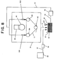
- slurry 62 contained in a slurry tank 60 is pressurized by a pump 66, fed to a slurry feed nozzle 50A or 50B through a slurry feed pipe 64, and then discharged onto a wire 12 from the slurry feed nozzle 50A or 50B, thereby being used for slicing the workpiece 40.
- Slurry scattering from a portion of the workpiece 40 being sliced, the wire 12, etc. is collected in the bottom portion of a wire saw cover 70.
- the thus-collected slurry is returned to the slurry tank 60 and then fed again to a portion of the workpiece 40 subjected to slicing through the slurry feed pipe 64, thereby being circulated for repeated use.
- the slurry tank 60 has a slurry viscosity detector 61.
- a slurry viscosity control agent is fed from a viscosity control agent tank 80 to the slurry tank 60 through a viscosity control agent feed pipe 82.
- a solenoid valve 84 is provided in the viscosity control agent feed pipe 82. The opening of the solenoid valve 84 is controlled according to the viscosity of the slurry detected by the slurry viscosity detector 61 as well as according to the cutting length in a workpiece or the angle between a wire and the circumference of a workpiece, thereby adjusting the viscosity of the slurry contained in the slurry tank 60.
- a resulting signal from the signal processor is used to open/close the solenoid valve 84 so as to adjust the viscosity of the slurry.
- a generally employed viscometer may be used as the viscosity detector 61.
- the viscosity of the slurry is obtained with a mass flowmeter or through the measurement of an electric conductivity. This is because a so-called on-line viscosity measurement can be implemented, so that the viscosity of the slurry can be controlled and managed accurately and readily.
- a slurry stirrer 63 is preferably provided within the slurry tank 60.
- a generally employed method for example, a rotating mechanism for rotating a stirring rod immersed in the slurry 62 with a motor, an oscillating mechanism, a vibrating mechanism, or the like.
- the cutting length can be determined from the relative position between the wire 12 and the workpiece 40, for example, from the diameter of the workpiece 40 and the feed amount of the workpiece holder 42 relative to the wire 12.
- slurry is usually circulated. Since heat generated during the slicing of a workpiece causes water to evaporate from slurry, slurry collected in the slurry tank 60 has a very high viscosity. Of components of the slurry, abrasive grains and coolant are collected in a substantially whole quantity, since the abrasive grains are solid and the coolant is nonvolatile. Accordingly, what is lost from slurry during the slicing of a workpiece is water serving as a medium of the slurry.
- the viscosity of the slurry can be adjusted. That is, by controlling the amount of water serving as a viscosity control agent and fed from the viscosity control agent tank 80, the viscosity of the slurry in the slurry tank 60 can be adjusted as desired.
- a coolant component of the slurry is preferably water-soluble so as to be uniformly mixed with water.
- the viscosity of the slurry is adjusted according to the cutting length in a workpiece or the angle between a wire and the circumference of the workpiece, thereby uniformizing the thickness of each sliced wafer. That is, as represented by a pattern of the viscosity of the slurry shown in FIG. 9, the viscosity of the slurry is minimized when slicing is started, and then increased with the cutting length until it is maximized for slicing a workpiece at the central portion thereof. Subsequently, the viscosity of the slurry is decreased as the cutting length decreases.
- the viscosity of the slurry is varied such that as compared with the rate of increase in the viscosity of the slurry during slicing from a slicing start portion to the central portion of a cylindrical workpiece, the rate of decrease in the viscosity of the slurry during slicing from the central portion of the workpiece to a slicing end portion is made lower.
- An ingot of silicon single-crystal semiconductor having a diameter of approximately 200 mm was sliced using a wire saw and method of the present invention.
- the viscosity of the slurry was varied according to a pattern shown in FIG. 9, which defines a variation in the viscosity of the slurry with respect to the cutting depth in the workpiece.
- the viscosity of the slurry was 35 mPa ⁇ s when slicing was started, then was increased with the cutting length in the ingot until it reaches 100 mPa ⁇ s for slicing the ingot at the central portion thereof, and subsequently decreased with the cutting length until it reaches 60 mPa ⁇ s for slicing the ingot at the slicing end portion thereof.
- An ingot of silicon single-crystal semiconductor having a diameter of approximately 200 mm was sliced in a manner similar to that of Example 3 except that the viscosity of the slurry was maintained constant at 60 mPa ⁇ s during slicing. 5 ingots were sliced to obtain approximately 1000 wafers. The thickness of each of the thus-obtained wafers was measured at 5 points, namely a wafer center and 4 peripheral points (located 3mm inside as measured from the wafer edge), as shown in FIG. 6, thereby obtaining a difference TV5 between the maximum and minimum thickness measurements.
- An ingot of silicon single-crystal semiconductor having a diameter of approximately 200 mm was sliced in a manner similar to that of Example 3 except that the viscosity of the slurry was maintained constant at 80 mPa ⁇ s during slicing. 5 ingots were sliced to obtain approximately 1000 wafers. The thickness of each of the thus-obtained wafers was measured at 5 points, namely a wafer center and 4 peripheral points (located 3mm inside as measured from the wafer edge), as shown in FIG. 6, thereby obtaining a difference TV5 between the maximum and minimum thickness measurements.
- Table 2 shows the test results of Example 3 and Comparative Examples 2 and 3.
- Table 2 Ingots (pcs) Wafers (pcs) Average TV5 ( ⁇ m) Crack generation (%)
- water was used as a viscosity control agent.
- the present invention is not to be limited thereto.
- any of various organic solvents or the like may be used.
- a solenoid valve was used to control the amount of feed of a viscosity control agent.
- the present invention is not to be limited thereto. Any of other generally used valves, flowmeters, or the like may be used so long as they can control the amount of feed of a viscosity control agent.
- the feed rate of a wire 12 for slicing a workpiece 40 is varied according to the cutting length in the workpiece 40 or the angle between the wire 12 and the circumference of the workpiece 40.
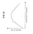
- FIG. 10 shows a pattern of varying the feed rate of the wire 12. The feed rate of the wire 12 is lowest when slicing starts, then is increased with the cutting length in the workpiece 40 until it reaches a maximum for slicing the workpiece 40 at the central portion thereof, and subsequently decreased as the cutting length decreases.
- the wire feed rate is varied such that as compared with the rate of increase in the wire feed rate during slicing from a slicing start portion to the central portion of a cylindrical workpiece, the rate of decrease in the wire feed rate during slicing from the central portion of the workpiece to a slicing end portion is made lower.
- This variation of the wire feed rate copes with the fact that as shown in FIG. 1A, the work amount of a wire and slurry on a cylindrical workpiece is relatively small during slicing from the central portion of the workpiece to a slicing end point as compared with slicing from a slicing start point to the central portion of the workpiece.
- a servomotor for example, may be used as a drive motor 7 connected to a roller 10C to rotate the roller 10C.
- the feed rate of the wire 12 can be controlled according to a predetermined pattern.
- the wire take-up/release rate of wire take-up reed bobbins 22 and 32 may be controlled by means of torque motors 24 and 34.
- the cutting length can be determined from the relative position between the wire 12 and the workpiece 40, for example, from the diameter of the workpiece 40 and the feed amount of the workpiece holder 42 relative to the wire 12.
- An ingot of silicon single-crystal semiconductor having a diameter of approximately 200 mm was sliced using a wire saw and method of the present invention.
- a wire feed rate was varied according to a pattern shown in FIG. 10, which defines a variation in the wire feed rate with respect to the cutting depth in the workpiece.
- the wire feed rate was 100 m/min when slicing was started, then was increased with the cutting length in the ingot until it reaches 650 m/min for slicing the ingot at the central portion thereof, and subsequently decreased with the cutting length until it reaches 300 m/min for slicing the ingot at the slicing end portion thereof.
- An ingot of silicon single-crystal semiconductor having a diameter of approximately 200 mm was sliced in a manner similar to that of Example 4 except that the wire feed rate was maintained constant at 500 m/min during slicing. 5 ingots were sliced to obtain approximately 1000 wafers. The thickness of each of the thus-obtained wafers was measured at 5 points, namely a wafer center and 4 peripheral points (located 3mm inside as measured from the wafer edge), as shown in FIG. 6, thereby obtaining a difference TV5 between the maximum and minimum thickness measurements.
- Table 3 shows the test results of Example 4 and Comparative Example 4.
- Table 3 Ingots (pcs) Wafers (pcs) Average TV5 ( ⁇ m) Crack generation (%)
- FIG. 1B The cross-section of those wafers which are obtained through the use of a method and apparatus of the present invention is as shown in FIG. 1B, whereas the cross-section of those wafers which are obtained through the use of a conventional method and apparatus or in Comparative Examples 1 to 4 is convex on both sides thereof as shown in FIG. 1A, indicating that the present invention provides a significant improvement.
- Tables 1-3 compared with Comparative Examples 1 to 4, Examples 1 to 4 of the present invention show a smaller value of TV5 that indicates the degree of variation in the thickness of each wafer. Further, Examples 1 to 4 show a significant improvement in a crack generation percentage with wafers, probably owing to a smooth flat cut surface, as shown in FIG. 1B. Accordingly, the present invention can decrease variation in the thickness of each wafer while improving the yield of slicing and productivity.
- Cylindrical workpiece does not necessarily denote the only prismatic workpiece having a completely circular cross-section.
- Cylindrical workpieces include workpieces having an elliptic cross-section, workpieces having a circular cross-section and a partial cut (so-called orientation flat), and the like. So long as a workpiece has a cross-section such that the cutting length or the angle between a wire and the circumference of the workpiece varies as slicing progresses, a pattern of varying a slurry feed rate, a slurry viscosity or a wire feed rate may be determined accordingly.
Landscapes
- Engineering & Computer Science (AREA)
- Mechanical Engineering (AREA)
- Processing Of Stones Or Stones Resemblance Materials (AREA)
- Mechanical Treatment Of Semiconductor (AREA)
- Finish Polishing, Edge Sharpening, And Grinding By Specific Grinding Devices (AREA)
Priority Applications (2)
| Application Number | Priority Date | Filing Date | Title |
|---|---|---|---|
| EP03019947A EP1371467B1 (de) | 1996-03-26 | 1997-03-26 | Drahtsäge und Verfahren zum Zerschneiden eines zylindrischen Werkstücks |
| EP02024494A EP1287958A1 (de) | 1996-03-26 | 1997-03-26 | Drahtsäge und Verfahren zum Zerschneiden eines zylindrischen Werkstücks |
Applications Claiming Priority (9)
| Application Number | Priority Date | Filing Date | Title |
|---|---|---|---|
| JP96165/96 | 1996-03-26 | ||
| JP9616596 | 1996-03-26 | ||
| JP96164/96 | 1996-03-26 | ||
| JP9616596A JP3202591B2 (ja) | 1996-03-26 | 1996-03-26 | ワイヤーソー及び円柱形ワークを切断する方法 |
| JP96163/96 | 1996-03-26 | ||
| JP9616396 | 1996-03-26 | ||
| JP9616496A JP3810125B2 (ja) | 1996-03-26 | 1996-03-26 | ワイヤーソー及び円柱形ワークを切断する方法 |
| JP9616396A JP3202590B2 (ja) | 1996-03-26 | 1996-03-26 | ワイヤーソー及び円柱形ワークを切断する方法 |
| JP9616496 | 1996-03-26 |
Related Child Applications (1)
| Application Number | Title | Priority Date | Filing Date |
|---|---|---|---|
| EP02024494A Division EP1287958A1 (de) | 1996-03-26 | 1997-03-26 | Drahtsäge und Verfahren zum Zerschneiden eines zylindrischen Werkstücks |
Publications (3)
| Publication Number | Publication Date |
|---|---|
| EP0798091A2 true EP0798091A2 (de) | 1997-10-01 |
| EP0798091A3 EP0798091A3 (de) | 1998-08-19 |
| EP0798091B1 EP0798091B1 (de) | 2003-05-14 |
Family
ID=27308018
Family Applications (2)
| Application Number | Title | Priority Date | Filing Date |
|---|---|---|---|
| EP03019947A Expired - Lifetime EP1371467B1 (de) | 1996-03-26 | 1997-03-26 | Drahtsäge und Verfahren zum Zerschneiden eines zylindrischen Werkstücks |
| EP97302064A Expired - Lifetime EP0798091B1 (de) | 1996-03-26 | 1997-03-26 | Drahtsäge und Verfahren zum Zerschneiden eines zylindrischen Werkstücks, wie Ingots |
Family Applications Before (1)
| Application Number | Title | Priority Date | Filing Date |
|---|---|---|---|
| EP03019947A Expired - Lifetime EP1371467B1 (de) | 1996-03-26 | 1997-03-26 | Drahtsäge und Verfahren zum Zerschneiden eines zylindrischen Werkstücks |
Country Status (5)
| Country | Link |
|---|---|
| US (1) | US5937844A (de) |
| EP (2) | EP1371467B1 (de) |
| DE (2) | DE69734790T2 (de) |
| MY (1) | MY120514A (de) |
| TW (1) | TW330884B (de) |
Cited By (8)
| Publication number | Priority date | Publication date | Assignee | Title |
|---|---|---|---|---|
| WO2000038023A1 (de) * | 1998-12-22 | 2000-06-29 | Deutsche Solar Gmbh | Verfahren zur kontrolle eines sägeprozesses |
| DE102005007312B4 (de) * | 2004-04-29 | 2006-07-27 | Siltronic Ag | Verfahren zum gleichzeitigen Abtrennen einer Vielzahl von Scheiben mit verringerter Welligkeit von einem zylindrischen Werkstück |
| US7971584B2 (en) | 2006-07-13 | 2011-07-05 | Siltronic Ag | Sawing strip and method for simultaneously cutting off a multiplicity of slices from a cylindrical workpiece using a sawing strip |
| DE102012201938A1 (de) | 2012-02-09 | 2013-08-14 | Siltronic Ag | Vorrichtung und Verfahren zum gleichzeitigen Trennen einer Vielzahl von Scheiben von einem Werkstück |
| DE102012203275A1 (de) | 2012-03-01 | 2013-09-05 | Siltronic Ag | Vorrichtung und Verfahren zum gleichzeitigen Trennen einer Vielzahl von Scheiben von einem Werkstück |
| DE102013219468A1 (de) * | 2013-09-26 | 2015-03-26 | Siltronic Ag | Verfahren zum gleichzeitigen Trennen einer Vielzahl von Scheiben von einem Werkstück |
| DE102014208187A1 (de) | 2014-04-30 | 2015-11-05 | Siltronic Ag | Verfahren zum gleichzeitigen Trennen einer Vielzahl von Scheiben mit besonders gleichmäßiger Dicke von einem Werkstück |
| WO2021013238A1 (zh) * | 2019-07-24 | 2021-01-28 | 徐州鑫晶半导体科技有限公司 | 切割硅棒的方法和金刚石多线切割装置 |
Families Citing this family (27)
| Publication number | Priority date | Publication date | Assignee | Title |
|---|---|---|---|---|
| TW383249B (en) * | 1998-09-01 | 2000-03-01 | Sumitomo Spec Metals | Cutting method for rare earth alloy by annular saw and manufacturing for rare earth alloy board |
| JP4066112B2 (ja) * | 1999-01-28 | 2008-03-26 | 株式会社スーパーシリコン研究所 | ワイヤソーの制御方法及びワイヤソー |
| US6112738A (en) * | 1999-04-02 | 2000-09-05 | Memc Electronics Materials, Inc. | Method of slicing silicon wafers for laser marking |
| JP3389141B2 (ja) * | 1999-04-26 | 2003-03-24 | 株式会社スーパーシリコン研究所 | スライシング用スラリーの評価方法及びスラリー |
| CN1175961C (zh) * | 1999-09-17 | 2004-11-17 | 株式会社新王磁材 | 稀土合金的切割方法和切割装置 |
| MY126994A (en) | 1999-12-14 | 2006-11-30 | Hitachi Metals Ltd | Method and apparatus for cutting a rare earth alloy |
| AU2000251024A1 (en) | 2000-05-31 | 2001-12-11 | Memc Electronic Materials S.P.A. | Wire saw and process for slicing multiple semiconductor ingots |
| US6889684B2 (en) * | 2002-11-06 | 2005-05-10 | Seh America, Inc. | Apparatus, system and method for cutting a crystal ingot |
| CH696431A5 (fr) * | 2003-04-01 | 2007-06-15 | Hct Shaping Systems Sa | Procédé et dispositif de sciage par fil. |
| KR100667690B1 (ko) * | 2004-11-23 | 2007-01-12 | 주식회사 실트론 | 웨이퍼 슬라이싱 방법 및 장치 |
| JP4951914B2 (ja) * | 2005-09-28 | 2012-06-13 | 信越半導体株式会社 | (110)シリコンウエーハの製造方法 |
| DE102006050330B4 (de) * | 2006-10-25 | 2009-10-22 | Siltronic Ag | Verfahren zum gleichzeitigen Auftrennen von wenigstens zwei zylindrischen Werkstücken in eine Vielzahl von Scheiben |
| FR2927272B1 (fr) * | 2008-02-07 | 2010-05-21 | Saint Gobain Ct Recherches | Poudre de grains abrasifs. |
| SG172286A1 (en) * | 2008-12-20 | 2011-07-28 | Cabot Microelectronics Corp | Wiresaw cutting method |
| FR2947831B1 (fr) | 2009-07-09 | 2012-02-03 | Saint Gobain Ct Recherches | Suspension de grains abrasifs |
| JP5515593B2 (ja) * | 2009-10-07 | 2014-06-11 | 株式会社Sumco | ワイヤーソーによるシリコンインゴットの切断方法およびワイヤーソー |
| GB2476658A (en) * | 2009-12-30 | 2011-07-06 | Rec Wafer Norway As | Process for cutting a block using a planar array of wires |
| US9833854B2 (en) * | 2010-05-18 | 2017-12-05 | Mitsubishi Electric Corporation | Workpiece retainer, wire electric discharge machining device, thin-plate manufacturing method, and semiconductor-wafer manufacturing method |
| CN101973081B (zh) * | 2010-07-28 | 2012-07-18 | 常州天合光能有限公司 | 利用mb线锯切截头不截尾8寸多晶块的方法 |
| DE102012209974B4 (de) * | 2012-06-14 | 2018-02-15 | Siltronic Ag | Verfahren zum gleichzeitigen Abtrennen einer Vielzahl von Scheiben von einem zylindrischen Werkstück |
| JP6015598B2 (ja) * | 2013-08-28 | 2016-10-26 | 信越半導体株式会社 | インゴットの切断方法及びワイヤソー |
| CN108162213A (zh) * | 2017-12-07 | 2018-06-15 | 上海申和热磁电子有限公司 | 一种减小硅片多线切割时硅片翘曲的方法 |
| CN109571218A (zh) * | 2018-12-21 | 2019-04-05 | 西安奕斯伟硅片技术有限公司 | 研磨剂喷淋控制结构、工件切割系统及喷淋方法 |
| CN110466085B (zh) * | 2019-07-24 | 2021-02-05 | 徐州鑫晶半导体科技有限公司 | 切割硅棒的方法 |
| CN114571617B (zh) * | 2022-03-24 | 2022-09-16 | 广东高景太阳能科技有限公司 | 一种硅片切割中砂浆喷射控制方法及控制系统 |
| CN114633387A (zh) * | 2022-04-06 | 2022-06-17 | 广东高景太阳能科技有限公司 | 一种大尺寸硅片提料过程防止挂线的装置及方法 |
| CN119427569A (zh) * | 2024-11-29 | 2025-02-14 | 西安奕斯伟材料科技股份有限公司 | 切削液喷淋装置、多线切割设备及多线切割方法 |
Family Cites Families (15)
| Publication number | Priority date | Publication date | Assignee | Title |
|---|---|---|---|---|
| US3599623A (en) * | 1969-09-02 | 1971-08-17 | Fairchild Camera Instr Co | Cutting apparatus for making finely controlled cuts utilizing a tiltable wheel for regulating the cutting blade movement |
| US3831576A (en) * | 1971-11-22 | 1974-08-27 | Motorola Inc | Machine and method for cutting brittle materials using a reciprocating cutting wire |
| US3841297A (en) * | 1971-12-01 | 1974-10-15 | Motorola Inc | Machine for cutting brittle materials |
| US4038962A (en) * | 1976-08-25 | 1977-08-02 | Coggins Industries, Inc. | Automatic power controller for a wire saw |
| JPS5741118A (en) * | 1980-08-22 | 1982-03-08 | Sumitomo Electric Ind Ltd | Cutting of work |
| JPH0777696B2 (ja) * | 1985-11-22 | 1995-08-23 | 株式会社井上ジャパックス研究所 | ワイヤカツト放電加工装置 |
| JPS6478802A (en) * | 1987-09-19 | 1989-03-24 | Daiwa Kikai Seisakusho | Cutting of high-hardness brittle material cutting machine utilizing diamond wire saw |
| JP2673544B2 (ja) * | 1988-06-14 | 1997-11-05 | 株式会社日平トヤマ | 脆性材料の切断方法 |
| IT1236877B (it) * | 1989-11-22 | 1993-04-26 | Telaio perfezionato per la segagione in lastre di blocchi di materiale lapideo. | |
| JP2516717B2 (ja) * | 1991-11-29 | 1996-07-24 | 信越半導体株式会社 | ワイヤソ―及びその切断方法 |
| JP2967896B2 (ja) * | 1993-06-18 | 1999-10-25 | 信越化学工業株式会社 | ウエーハの製造方法 |
| JP3283113B2 (ja) * | 1993-08-19 | 2002-05-20 | 信越化学工業株式会社 | ウエーハの製造方法 |
| DE19510625A1 (de) * | 1995-03-23 | 1996-09-26 | Wacker Siltronic Halbleitermat | Drahtsäge und Verfahren zum Abtrennen von Scheiben von einem Werkstück |
| US5564409A (en) * | 1995-06-06 | 1996-10-15 | Corning Incorporated | Apparatus and method for wire cutting glass-ceramic wafers |
| JPH0985736A (ja) * | 1995-09-22 | 1997-03-31 | Toray Eng Co Ltd | ワイヤ式切断装置 |
-
1997
- 1997-03-24 MY MYPI97001229A patent/MY120514A/en unknown
- 1997-03-24 US US08/823,208 patent/US5937844A/en not_active Expired - Lifetime
- 1997-03-24 TW TW086103678A patent/TW330884B/zh not_active IP Right Cessation
- 1997-03-26 EP EP03019947A patent/EP1371467B1/de not_active Expired - Lifetime
- 1997-03-26 DE DE69734790T patent/DE69734790T2/de not_active Expired - Lifetime
- 1997-03-26 EP EP97302064A patent/EP0798091B1/de not_active Expired - Lifetime
- 1997-03-26 DE DE69721881T patent/DE69721881T2/de not_active Expired - Lifetime
Cited By (15)
| Publication number | Priority date | Publication date | Assignee | Title |
|---|---|---|---|---|
| WO2000038023A1 (de) * | 1998-12-22 | 2000-06-29 | Deutsche Solar Gmbh | Verfahren zur kontrolle eines sägeprozesses |
| DE102005007312B4 (de) * | 2004-04-29 | 2006-07-27 | Siltronic Ag | Verfahren zum gleichzeitigen Abtrennen einer Vielzahl von Scheiben mit verringerter Welligkeit von einem zylindrischen Werkstück |
| US7971584B2 (en) | 2006-07-13 | 2011-07-05 | Siltronic Ag | Sawing strip and method for simultaneously cutting off a multiplicity of slices from a cylindrical workpiece using a sawing strip |
| DE102012201938B4 (de) * | 2012-02-09 | 2015-03-05 | Siltronic Ag | Verfahren zum gleichzeitigen Trennen einer Vielzahl von Scheiben von einem Werkstück |
| DE102012201938A1 (de) | 2012-02-09 | 2013-08-14 | Siltronic Ag | Vorrichtung und Verfahren zum gleichzeitigen Trennen einer Vielzahl von Scheiben von einem Werkstück |
| US9346188B2 (en) | 2012-02-09 | 2016-05-24 | Siltronic Ag | Apparatus and method for simultaneously slicing a multiplicity of slices from a workpiece |
| DE102012203275A1 (de) | 2012-03-01 | 2013-09-05 | Siltronic Ag | Vorrichtung und Verfahren zum gleichzeitigen Trennen einer Vielzahl von Scheiben von einem Werkstück |
| WO2013127847A1 (de) | 2012-03-01 | 2013-09-06 | Siltronic Ag | Vorrichtung und verfahren zum gleichzeitigen trennen einer vielzahl von scheiben von einem werkstück |
| DE102013219468A1 (de) * | 2013-09-26 | 2015-03-26 | Siltronic Ag | Verfahren zum gleichzeitigen Trennen einer Vielzahl von Scheiben von einem Werkstück |
| DE102013219468B4 (de) * | 2013-09-26 | 2015-04-23 | Siltronic Ag | Verfahren zum gleichzeitigen Trennen einer Vielzahl von Scheiben von einem Werkstück |
| DE102014208187A1 (de) | 2014-04-30 | 2015-11-05 | Siltronic Ag | Verfahren zum gleichzeitigen Trennen einer Vielzahl von Scheiben mit besonders gleichmäßiger Dicke von einem Werkstück |
| US9573296B2 (en) | 2014-04-30 | 2017-02-21 | Siltronic Ag | Method for simultaneously cutting a multiplicity of slices of particularly uniform thickness from a workpiece |
| DE102014208187B4 (de) | 2014-04-30 | 2023-07-06 | Siltronic Ag | Verfahren zum gleichzeitigen Trennen einer Vielzahl von Scheiben mit besonders gleichmäßiger Dicke von einem Werkstück |
| WO2021013238A1 (zh) * | 2019-07-24 | 2021-01-28 | 徐州鑫晶半导体科技有限公司 | 切割硅棒的方法和金刚石多线切割装置 |
| US12122067B2 (en) | 2019-07-24 | 2024-10-22 | Zhonghuan Advanced Semiconductor Technology Co., Ltd. | Method for cutting silicon rod and apparatus for dimaond multi-wire cutting |
Also Published As
| Publication number | Publication date |
|---|---|
| EP0798091A3 (de) | 1998-08-19 |
| DE69734790D1 (de) | 2006-01-05 |
| DE69734790T2 (de) | 2006-08-17 |
| DE69721881T2 (de) | 2004-05-19 |
| TW330884B (en) | 1998-05-01 |
| EP0798091B1 (de) | 2003-05-14 |
| EP1371467A1 (de) | 2003-12-17 |
| US5937844A (en) | 1999-08-17 |
| MY120514A (en) | 2005-11-30 |
| EP1371467B1 (de) | 2005-11-30 |
| DE69721881D1 (de) | 2003-06-18 |
Similar Documents
| Publication | Publication Date | Title |
|---|---|---|
| EP0798091A2 (de) | Drahtsäge und Verfahren zum Zerschneiden eines zylindrischen Werkstücks, wie Ingots | |
| KR100350657B1 (ko) | 경질의 취성가공물에서 다수의 디스크를 절삭하는 방법 및 그 장치 | |
| KR101476670B1 (ko) | 절단 방법 및 와이어 쏘 장치 | |
| KR100888989B1 (ko) | 공작물로부터 다수의 웨이퍼를 슬라이싱하는 방법 | |
| US6006738A (en) | Method and apparatus for cutting an ingot | |
| JP3427956B2 (ja) | ワイヤーソー装置 | |
| US5699782A (en) | Wire saw apparatus | |
| US7195542B2 (en) | Process, apparatus and slurry for wire sawing | |
| EP1287958A1 (de) | Drahtsäge und Verfahren zum Zerschneiden eines zylindrischen Werkstücks | |
| JP2008198906A (ja) | シリコンウェーハの製造方法 | |
| TWI861261B (zh) | 線鋸之運轉重啟方法 | |
| TWI692394B (zh) | 線鋸裝置 | |
| JP3775044B2 (ja) | ワイヤソー加工方法およびワイヤソー加工装置 | |
| JP2000288902A (ja) | 固定砥粒付ワイヤ及び固定砥粒ワイヤソー | |
| TW202039149A (zh) | 工件之切斷方法及工件之切斷裝置 | |
| CN1082865C (zh) | 切割锭块用的方法和装置 | |
| US4811722A (en) | Process for sharpening cutting-off tools and cutting-off process | |
| EP0457626B1 (de) | Verfahren und Vorrichtung zum Zerschneiden von Einkristallbarren mittels einer Innenlochsäge | |
| JP3202591B2 (ja) | ワイヤーソー及び円柱形ワークを切断する方法 | |
| US6554686B1 (en) | Sawing wire and method for the cutting and lapping of hard brittle workpieces | |
| JP3202590B2 (ja) | ワイヤーソー及び円柱形ワークを切断する方法 | |
| US5388374A (en) | Apparatus and method for grinding points | |
| CN118219447A (zh) | 晶棒切割的砂浆更换方法及砂浆更换装置 | |
| SU1689089A1 (ru) | Способ струнной резки полупроводниковых кристаллов | |
| JP3810125B2 (ja) | ワイヤーソー及び円柱形ワークを切断する方法 |
Legal Events
| Date | Code | Title | Description |
|---|---|---|---|
| PUAI | Public reference made under article 153(3) epc to a published international application that has entered the european phase |
Free format text: ORIGINAL CODE: 0009012 |
|
| AK | Designated contracting states |
Kind code of ref document: A2 Designated state(s): DE FR GB |
|
| PUAL | Search report despatched |
Free format text: ORIGINAL CODE: 0009013 |
|
| AK | Designated contracting states |
Kind code of ref document: A3 Designated state(s): DE FR GB |
|
| 17P | Request for examination filed |
Effective date: 19981127 |
|
| 17Q | First examination report despatched |
Effective date: 20020313 |
|
| GRAH | Despatch of communication of intention to grant a patent |
Free format text: ORIGINAL CODE: EPIDOS IGRA |
|
| GRAH | Despatch of communication of intention to grant a patent |
Free format text: ORIGINAL CODE: EPIDOS IGRA |
|
| GRAA | (expected) grant |
Free format text: ORIGINAL CODE: 0009210 |
|
| AK | Designated contracting states |
Designated state(s): DE FR GB |
|
| REG | Reference to a national code |
Ref country code: GB Ref legal event code: FG4D |
|
| REF | Corresponds to: |
Ref document number: 69721881 Country of ref document: DE Date of ref document: 20030618 Kind code of ref document: P |
|
| ET | Fr: translation filed | ||
| PLBE | No opposition filed within time limit |
Free format text: ORIGINAL CODE: 0009261 |
|
| STAA | Information on the status of an ep patent application or granted ep patent |
Free format text: STATUS: NO OPPOSITION FILED WITHIN TIME LIMIT |
|
| 26N | No opposition filed |
Effective date: 20040217 |
|
| REG | Reference to a national code |
Ref country code: FR Ref legal event code: PLFP Year of fee payment: 20 |
|
| PGFP | Annual fee paid to national office [announced via postgrant information from national office to epo] |
Ref country code: DE Payment date: 20160322 Year of fee payment: 20 |
|
| PGFP | Annual fee paid to national office [announced via postgrant information from national office to epo] |
Ref country code: FR Payment date: 20160208 Year of fee payment: 20 Ref country code: GB Payment date: 20160323 Year of fee payment: 20 |
|
| REG | Reference to a national code |
Ref country code: DE Ref legal event code: R071 Ref document number: 69721881 Country of ref document: DE |
|
| REG | Reference to a national code |
Ref country code: GB Ref legal event code: PE20 Expiry date: 20170325 |
|
| PG25 | Lapsed in a contracting state [announced via postgrant information from national office to epo] |
Ref country code: GB Free format text: LAPSE BECAUSE OF EXPIRATION OF PROTECTION Effective date: 20170325 |