EP0798123A2 - Mechanismus zum Führen von Endlos- und Einzelpapier für ein Bildaufzeichnungsgerät - Google Patents
Mechanismus zum Führen von Endlos- und Einzelpapier für ein Bildaufzeichnungsgerät Download PDFInfo
- Publication number
- EP0798123A2 EP0798123A2 EP97105266A EP97105266A EP0798123A2 EP 0798123 A2 EP0798123 A2 EP 0798123A2 EP 97105266 A EP97105266 A EP 97105266A EP 97105266 A EP97105266 A EP 97105266A EP 0798123 A2 EP0798123 A2 EP 0798123A2
- Authority
- EP
- European Patent Office
- Prior art keywords
- recording medium
- roller
- convey
- image
- drive
- Prior art date
- Legal status (The legal status is an assumption and is not a legal conclusion. Google has not performed a legal analysis and makes no representation as to the accuracy of the status listed.)
- Granted
Links
Images



Classifications
-
- B—PERFORMING OPERATIONS; TRANSPORTING
- B65—CONVEYING; PACKING; STORING; HANDLING THIN OR FILAMENTARY MATERIAL
- B65H—HANDLING THIN OR FILAMENTARY MATERIAL, e.g. SHEETS, WEBS, CABLES
- B65H20/00—Advancing webs
- B65H20/20—Advancing webs by web-penetrating means, e.g. pins
- B65H20/22—Advancing webs by web-penetrating means, e.g. pins to effect step-by-step advancement of web
-
- B—PERFORMING OPERATIONS; TRANSPORTING
- B41—PRINTING; LINING MACHINES; TYPEWRITERS; STAMPS
- B41J—TYPEWRITERS; SELECTIVE PRINTING MECHANISMS, i.e. MECHANISMS PRINTING OTHERWISE THAN FROM A FORME; CORRECTION OF TYPOGRAPHICAL ERRORS
- B41J11/00—Devices or arrangements of selective printing mechanisms, e.g. ink-jet printers or thermal printers, for supporting or handling copy material in sheet or web form
- B41J11/26—Pin feeds
-
- B—PERFORMING OPERATIONS; TRANSPORTING
- B41—PRINTING; LINING MACHINES; TYPEWRITERS; STAMPS
- B41J—TYPEWRITERS; SELECTIVE PRINTING MECHANISMS, i.e. MECHANISMS PRINTING OTHERWISE THAN FROM A FORME; CORRECTION OF TYPOGRAPHICAL ERRORS
- B41J11/00—Devices or arrangements of selective printing mechanisms, e.g. ink-jet printers or thermal printers, for supporting or handling copy material in sheet or web form
- B41J11/48—Apparatus for condensed record, tally strip, or like work using two or more papers, or sets of papers, e.g. devices for switching over from handling of copy material in sheet form to handling of copy material in continuous form and vice versa or point-of-sale printers comprising means for printing on continuous copy material, e.g. journal for tills, and on single sheets, e.g. cheques or receipts
-
- B—PERFORMING OPERATIONS; TRANSPORTING
- B65—CONVEYING; PACKING; STORING; HANDLING THIN OR FILAMENTARY MATERIAL
- B65H—HANDLING THIN OR FILAMENTARY MATERIAL, e.g. SHEETS, WEBS, CABLES
- B65H5/00—Feeding articles separated from piles; Feeding articles to machines
- B65H5/06—Feeding articles separated from piles; Feeding articles to machines by rollers or balls, e.g. between rollers
- B65H5/062—Feeding articles separated from piles; Feeding articles to machines by rollers or balls, e.g. between rollers between rollers or balls
Definitions
- the present invention relates to an image recording apparatus in which a single sheet (for example, a cut sheet) and an elongated sheet (for example, a fan-fold sheet) can selectively be used. More particularly, it relates to an image recording apparatus including a convey means having a specific feature.
- a convey means for a recording medium there are provided a convey roller 450 and pinch rollers 451a, 451b urged against the convey roller to be followingly driven therewith, and a so-called U-turn path is formed so that the recording medium is conveyed around the convey roller 450.
- the cut sheet is pinched between the convey roller 450 and the pinch rollers 451a, 451b to be conveyed by a friction generated between the sheet and the rollers.
- a continuous sheet (referred to as "fan-fold sheet” hereinafter) is used as the recording medium, pin holes of the fan-fold sheet are engaged by pins 452a of a pin feed tractor (referred to merely as “tractor” hereinafter) 452, and the fan-fold sheet is pinched between the convey roller 450 and the pinch rollers 451a, 451b to be conveyed to a recording portion by a friction generated between the sheet and the rollers.
- a conveying amount of the sheet given by the tractor 452 is always the same as a conveying amount of the sheet given by the convey roller 450.
- the pinch rollers 451a, 451b are disengaged from the convey roller 450 so that a conveying force of the convey roller 450 is not transmitted to the fan-fold sheet.
- the recording medium After an image is recorded on the recording medium by a recording head 453 in response to image information, the recording medium is discharged by a sheet discharge roller 454 and a pinch roller 455 urged against the sheet discharge roller.
- the convey roller 450 is made of material such as rubber having relatively high frictional coefficient, a slipping condition of the surface of the roller is changed in accordance with the environmental condition.
- the coefficient of friction of the surface of the convey roller is greatly increased, so that, when the fan-fold sheet is conveyed around the convey roller, the conveying force acting on the fan-fold sheet cannot stably be reduced.
- the present invention intends to eliminate the above-mentioned conventional drawbacks, and has an object to provide an image recording apparatus having a convey means capable of properly conveying both a single sheet (for example, a cut sheet) and an elongated sheet (for example, a fan-fold sheet).
- a convey means capable of properly conveying both a single sheet (for example, a cut sheet) and an elongated sheet (for example, a fan-fold sheet).
- an image recording apparatus comprises an image recording means for recording an image on a recording medium, a first convey means for conveying the recording medium to an image recording portion of the image recording means while bending the recording medium along a drive convey roller by means of the drive convey roller, and a second convey means for conveying an elongated recording medium having a plurality of pin holes to the first convey means, and further comprising a guide means capable of changing a contact area between the recording medium and the drive convey roller at a bent portion of the recording medium along the drive convey roller.
- the contact area between the recording medium and the drive convey roller in accordance with the kind of the recording medium by using the guide means, a conveying force transmitted from the drive convey roller to the recording medium can be changed.
- the contact area may be decreased by the guide means, so that the conveying force transmitted from the first drive means may be decreased.
- a driven roller supported for movement to be engaged with or disengaged from the drive convey roller and having a switching means for selecting such engagement or disengagement
- when conveying the single recording medium it may be conveyed while being pinched between the drive convey roller and the driven roller; when conveying the elongated recording medium, it may be conveyed in a condition that the driven roller is disengaged from the drive convey roller.
- the guide means may be fixedly supported independently from the drive convey roller, and a guide member having a projection protruding toward the recording medium may be provided at a non-contact position between the driven roller and the drive convey roller.
- the guide member may be disposed coaxial with the drive convey roller. With this arrangement, the guide member can accurately be positioned with respect to the surface of the drive convey roller.
- the guide means may include a guide member shiftable, independently from the drive convey roller, between a first position to be protruded toward the recording medium and a second position not to be protruded toward the recording medium with respect to the drive convey roller, and a shift means for shifting the guide member.
- the guide member When the single recording medium is conveyed the guide member may be shifted to the first position, and when the elongated recording medium is conveyed it may be shifted to the second position.
- the guide member may be partially provided in a direction perpendicular to a recording medium conveying direction.
- the guide member may include a guide for directing the recording medium conveyed by the second convey means to a correct position of the first convey means. Further, the guide member may also include a guide for direction the recording medium from the first convey means to a correct position of the image recording portion.
- the guide member may be formed from conductive material and may be earthed.
- the second convey means may include a pin feed tractor so that the recording medium is conveyed while engaging pin holes of the recording medium by pins of the tractor.
- an image recording apparatus comprising an image recording means for recording an image on a recording medium, a drive convey roller for conveying the recording medium to an image recording portion of the image recording means while bending the recording medium along the drive convey roller, a driven (following rotating) roller capable of being engaged by and disengaged from the drive convey roller and capable of conveying the recording medium while pinching the recording medium between the drive convey roller and the driven roller, and a second convey means for conveying a recording medium having a plurality of pin holes to a nip between the drive convey roller and the driven roller, a guide member is provided at a bent portion and at position other than a nip between the drive convey roller and the driven roller. It has a protruded portion for conveying the recording medium while spacing the recording medium apart from the drive convey roller.
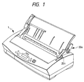
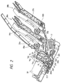
- Figs. 1, 2, 3A, 3B, 4, 5A, 5B and 6 show a first embodiment of the present invention. Now, a convey means which is a main characteristic of an image recording apparatus according to the first embodiment will be fully described.
- Fig. 1 is a perspective view showing a condition that an automatic sheet supply unit (also referred to as "ASF" (automatic sheet feeder) hereinafter
- Fig. 2 is a sectional view showing a condition that the ASF of Fig. 1 is mounted on the image forming apparatus by two pins.
- Fig. 3A is a perspective view showing a condition that a continuous sheet is set
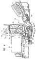
- Fig. 4 is a sectional view showing a condition that the continuous sheet is supplied.
- a single sheet such as a normal recording sheet, a post card and the like, and a continuous sheet such as a fan-fold sheet
- the sheet can be supplied by using the ASF or can be supplied by manual insertion.
- the ASF has two pins 30a, 30b.
- Sheet supply mechanisms of the pins 30a, 30b have the same construction, in which a plurality of cut sheets (not shown in Fig. 2) stacked on urging plates 31a, 31b are biased against pick-up rollers 33a, 33b by springs 32a, 32b, and the cut sheets can be separated and supplied one by one by means of the pick-up rollers 33a, 33b rotated in response to sheet supply command.
- a first convey means when the cut sheet is used will be explained.
- a release lever (switching means) 251 is set to a cut sheet supply mode
- a pinch roller (driven roller) 11 held on a pinch roller holder 5 is urged against a convey roller (drive convey roller) 10 by a pinch roller spring 245.
- an auxiliary roller (driven roller) 16 held by the pinch roller holder 5 for vertical movement is urged against the convey roller 10 by an auxiliary roller spring 248 provided on the pinch roller holder 5.
- the cut sheet supplied from the ASF can be conveyed to a recording area by a rotation of the convey roller 10 through a convey path formed around the convey roller.
- a needle roller 12 is held on a needle roller holder 223 and is biased against the convey roller 10 by a needle roller spring 246.
- flexion is generated in the needle roller spring 246 by a projection 241c formed on a release shaft 241, thereby providing an urging force by a spring elastic force acting around a contact point 246a between the spring and the projection.
- the cut sheet is subjected to an additional conveying force at this point and is passed through an image recording portion between a recording head 20 and a platen 24.
- the conveyance of the cut sheet is effected intermittently for each scan of the recording head 20, and a convey amount is determined in consideration of a length (in a cut sheet conveying direction) of an array of a plurality of image recording means provided in the recording head (ink discharge openings in case of an ink jet printer, and wires in case of a wire impact printer).
- the cut sheet is successively conveyed upwardly by a gap roller 13 and a sheet discharge roller 14 (and pinch rollers 13a, 14a urged against the gap roller and the sheet discharge roller, respectively) and then is discharged by a pinch roller 14b.
- the biasing force of the needle auxiliary spring 247 is not released. Therefore, when the continuous sheet is conveyed, the urging force of the needle roller 12 against the convey roller 10 is always maintained to a proper condition, without depending upon biasing forces of any springs other than the needle auxiliary spring 247.
- the continuous sheet conveyed to the recording area is successively conveyed upwardly by the intermittent conveyance after each scan of the recording head 20, and the recording is effected on the sheet.
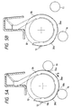
- Figs. 5A and 5B are schematic sectional views of a convey portion of the sheet convey system, where Fig. 5A shows a condition that the cut sheet is conveyed and Fig. 5B shows a condition that the continuous sheet is conveyed.
- Fig. 6 shows engagement positions of the pinch roller 11, auxiliary roller 16 and needle roller 12 against the convey roller.
- a series of grooves are formed in the convey roller 10 to divide the convey roller into a plurality of roller portions in a direction transverse to the sheet conveying direction, and guide members 26 are disposed in the respective grooves so that a roller surface and a guide surface are alternately exposed to the recording medium.
- the guide members are arranged in coaxial with the convey roller 10.
- the guide surfaces of the guide members 26 are retarded inwardly in comparison with the roller surface at the engagement positions 10a, 10b, 10c of the pinch roller 11, auxiliary roller 16 and needle roller 12 so that the pinch roller 11, auxiliary roller 16 and needle roller 12 are directly urged against the convey roller 10.
- the guide members 26 are disposed in the grooves 101, 102 so that contact areas between the convey roller 10 and the recording medium are substantially uniformly distributed in the main scan direction transverse to the sheet conveying direction.
- Fig. 5B shows the condition that the continuous sheet is conveyed.
- the pinch roller 11 and the auxiliary roller 16 are completely spaced apart from the convey roller 10, and the urging force of the needle roller 12 against the convey roller is weakened.
- the continuous sheet is conveyed on protruded portions 26a, 26b of the guide members 26 protruded outwardly from the roller surface.
- the guide members 26 are disposed at substantially the same intervals in the main scan direction transverse to the sheet conveying direction, the continuous sheet is not contacted with the convey roller 10 except for the nip between the needle roller 12 and the convey roller 10, with the result that the conveying force of the convey roller is almost not transmitted to the continuous sheet.
- the guide members 26 are disposed in coaxial with the convey roller 10, protruded amounts of the protruded portions 26a, 26b of the guide members 26 can be controlled accurately.
- a diameter D of the convey roller 10 is selected to 38.808 mm and radius R of each guide member at the engagement positions of the rollers 11, 16, 12 is selected to 18.9 mm.
- each guide member 26 is retarded inwardly from the surface of the convey roller 10 by about 0.5 mm. Further, the protruded portions 26a, 26b of the guide members 26 are protruded from the roller surface by about 0.5 mm.
- Figs. 7A and 7B are sectional views showing a convey portion of a sheet convey system according to the second embodiment, where Fig. 7A shows a condition that a cut sheet is conveyed, and Fig. 7B shows a condition that a continuous sheet is conveyed.
- Fig. 7A the pinch roller 11, auxiliary roller 16 and needle roller 12 are urged against the convey roller 10.
- An urging spring 29 is disposed between a bent portion 4a of a frame 4 and a tongue 26c of the guide member 26 to provide a biasing force.
- Fig. 8 shows a third embodiment of the present invention in which a guide member also acts as a guide for directing the recording medium to a correct position of the image recording portion. Since the other construction and function are the same as those of the first embodiment, the same elements are designated by the same reference numerals and explanation thereof will be omitted.
- the guide members are formed independently from the platen.
- the guide members also act as a platen. With this arrangement, the number of parts can be reduced, thereby making the apparatus cheaper.
- a projection may be provided on the guide member at an upstream side of the engagement position 10a between the convey roller 10 and the pinch roller 11 in the recording medium conveying direction, which projection acts as a guide for effecting registration of the recording medium.
- the guide members may be formed from conductive material and the convey roller 10 or the holder 4 may be earthed, thereby eliminating the static electricity.
- the conveying force transmitted from the drive convey roller to the recording medium can be changed by changing the contact area between the drive convey roller and the recording medium in accordance with the kind of the recording medium, thereby conveying the recording medium properly. That is to say, when the single sheet (cut sheet) is used, the adequate conveying force is transmitted from the drive convey roller to the cut sheet so that the sheet can be conveyed only by the first convey means.
- the conveying force of the drive convey roller is not transmitted to the fan-fold sheet, with the result that the sheet can be conveyed by the second convey means.
- the recording medium can be conveyed properly without occurrence of inconvenience due to the difference in convey amount between the first and second convey means.
- the guide means includes the guide member having the protruded portion protruded from the surface of the drive convey roller toward the recording medium in the condition that the driven roller is spaced apart from the drive convey roller, the recording medium does not contact with the drive convey roller, with the result that the conveying force is not transmitted from the drive convey roller to the recording medium. Further, by arranging the guide member in coaxial with the drive convey roller, the position of the guide member can be determined with respect to the roller surface of the drive convey roller with high accuracy.
- the guide means includes a guide member shiftable between a first position where it is protruded from the roller surface of the drive convey roller toward the recording medium and a second position where it is retracted from the roller surface, and a shift means for shifting the guide member, in the first position of the guide member, the recording medium does not contact with the drive convey roller, with the result that the conveying force is not transmitted from the drive convey roller to the recording medium.
- the guide members By providing the guide members intermittently in a direction transverse to the recording medium conveying direction, when the single recording medium is conveyed, the recording medium can be conveyed only by the conveying force of the drive convey roller.
- the guide member includes a guide for directing the recording medium (conveyed by the second convey means) to the correct position of the first convey means, more proper conveyance can be expected.
- the guide member may include a guide for directing the recording medium from the first convey means to the correct position of the image recording portion.
- a guide for directing the recording medium from the first convey means to the correct position of the image recording portion.
- the recording medium can properly be conveyed in accordance with the kind of the recording medium.
- the ink jet head used in the above-mentioned embodiments has heat generating elements disposed in nozzles for discharging ink, so that ink droplets are discharged from the nozzles by growth of bubbles generated in the ink by thermal energy of the heat generating element.
- the present invention provides an image recording apparatus comprising an image recording means for recording an image on a recording medium, a first convey means for conveying the recording medium to an image recording portion of the image recording means while bending the recording medium along a drive convey roller by means of the drive convey roller, and a second convey means for conveying an elongated recording medium having a plurality of pin holes to the first convey means. It further comprises a guide means capable of changing a contact area between the recording medium and the drive convey roller at a curved portion of the recording medium along the drive convey roller.
Landscapes
- Engineering & Computer Science (AREA)
- Mechanical Engineering (AREA)
- Delivering By Means Of Belts And Rollers (AREA)
- Handling Of Continuous Sheets Of Paper (AREA)
- Handling Of Sheets (AREA)
- Feeding Of Articles By Means Other Than Belts Or Rollers (AREA)
- Advancing Webs (AREA)
Applications Claiming Priority (3)
| Application Number | Priority Date | Filing Date | Title |
|---|---|---|---|
| JP10348096A JP3397575B2 (ja) | 1996-03-29 | 1996-03-29 | 画像記録装置 |
| JP10348096 | 1996-03-29 | ||
| JP103480/96 | 1996-03-29 |
Publications (3)
| Publication Number | Publication Date |
|---|---|
| EP0798123A2 true EP0798123A2 (de) | 1997-10-01 |
| EP0798123A3 EP0798123A3 (de) | 1997-11-05 |
| EP0798123B1 EP0798123B1 (de) | 2001-11-07 |
Family
ID=14355182
Family Applications (1)
| Application Number | Title | Priority Date | Filing Date |
|---|---|---|---|
| EP97105266A Expired - Lifetime EP0798123B1 (de) | 1996-03-29 | 1997-03-27 | Mechanismus zum Führen von Endlos- und Einzelpapier für ein Bildaufzeichnungsgerät |
Country Status (4)
| Country | Link |
|---|---|
| US (1) | US5899613A (de) |
| EP (1) | EP0798123B1 (de) |
| JP (1) | JP3397575B2 (de) |
| DE (1) | DE69707950T2 (de) |
Cited By (1)
| Publication number | Priority date | Publication date | Assignee | Title |
|---|---|---|---|---|
| EP2594402A1 (de) * | 2011-11-15 | 2013-05-22 | Seiko Epson Corporation | In einem Tintenstrahldrucker verwendetes Papier, Tintenstrahldrucker und Vorauswurfsverfahren für einen Tintenstrahldrucker |
Families Citing this family (18)
| Publication number | Priority date | Publication date | Assignee | Title |
|---|---|---|---|---|
| WO1999001287A1 (en) * | 1997-07-02 | 1999-01-14 | Citizen Watch Co., Ltd. | Flat bed printer |
| US6203223B1 (en) * | 1998-04-06 | 2001-03-20 | Seiko Epson Corporation | Printer |
| US6454476B1 (en) * | 1999-04-14 | 2002-09-24 | Hewlett-Packard Company | Apparatus and method for picking and feeding print media sheets |
| US6331002B1 (en) | 1999-07-29 | 2001-12-18 | Canon Kabushiki Kaisha | Sheet feeding apparatus |
| US7046380B2 (en) * | 2000-02-22 | 2006-05-16 | Canon Kabushiki Kaisha | Recording apparatus with feed control based on leading end margin amount |
| JP2002332137A (ja) | 2001-05-10 | 2002-11-22 | Canon Inc | 画像形成装置 |
| US7165765B2 (en) * | 2002-06-07 | 2007-01-23 | Canon Kabushiki Kaisha | Sheet feeding apparatus and recording apparatus |
| US7066670B2 (en) * | 2004-02-10 | 2006-06-27 | Tallygenicom Lp | Printing method and apparatus |
| JP4137008B2 (ja) | 2004-06-04 | 2008-08-20 | キヤノン株式会社 | 記録装置 |
| JP2006035802A (ja) * | 2004-07-30 | 2006-02-09 | Canon Inc | 記録装置 |
| US7976232B2 (en) * | 2007-02-12 | 2011-07-12 | Toshiba Tec Kabushiki Kaisha | Printer for feeding a cut sheet and a continuous sheet |
| TWI338622B (en) * | 2007-08-08 | 2011-03-11 | Avision Inc | Automatic paper feeding device |
| JP4995932B2 (ja) * | 2010-03-12 | 2012-08-08 | 株式会社沖データ | 印刷装置 |
| JP2012046312A (ja) | 2010-08-26 | 2012-03-08 | Canon Inc | 記録装置 |
| JP6191733B2 (ja) * | 2016-06-03 | 2017-09-06 | セイコーエプソン株式会社 | 液体噴射装置 |
| JP2018002359A (ja) * | 2016-06-29 | 2018-01-11 | セイコーエプソン株式会社 | 媒体搬送装置、画像読取装置 |
| JP7071115B2 (ja) | 2017-12-27 | 2022-05-18 | キヤノン株式会社 | 供給装置および記録装置 |
| JP7034749B2 (ja) | 2018-02-08 | 2022-03-14 | キヤノン株式会社 | 記録装置 |
Family Cites Families (13)
| Publication number | Priority date | Publication date | Assignee | Title |
|---|---|---|---|---|
| DE215976C (de) * | ||||
| DE8006136U1 (de) * | 1980-03-06 | 1980-06-19 | Triumph Werke Nuernberg Ag, 8500 Nuernberg | Vorrichtung zum abschwenken der papierwanne von der schreibwalze bei schreib- u.ae. bueromaschinen |
| DE3209085C2 (de) * | 1981-03-17 | 1986-03-27 | Canon K.K., Tokio/Tokyo | Papierzufuhrmechanismus |
| DD215976A1 (de) * | 1983-06-20 | 1984-11-28 | Robotron Bueromasch | Druckeinrichtung zur verarbeitung von endlos- und einzelformularen sowie formularsaetzen |
| JPS6294365A (ja) * | 1985-10-21 | 1987-04-30 | Tokyo Electric Co Ltd | 用紙送り装置 |
| US4789259A (en) * | 1986-01-13 | 1988-12-06 | Canon Kabushiki Kaisha | Cut sheet feed apparatus |
| EP0297486B1 (de) * | 1987-06-30 | 1993-09-08 | Seiko Epson Corporation | Papierzuführvorrichtung für Drucker |
| JPH0255169A (ja) * | 1988-08-20 | 1990-02-23 | Citizen Watch Co Ltd | 連続用紙・単票用紙両用プリンタ |
| JPH0441264A (ja) * | 1990-06-07 | 1992-02-12 | Canon Inc | 記録装置 |
| DE4104970A1 (de) * | 1991-02-19 | 1992-08-20 | Robotron Bueromasch Ag | Papierfuehrungseinrichtung bei papiervorschubeinrichtungen |
| JP3300418B2 (ja) * | 1992-08-20 | 2002-07-08 | ブラザー工業株式会社 | 印字装置 |
| JP3574169B2 (ja) * | 1993-12-03 | 2004-10-06 | セイコーエプソン株式会社 | プリンタ |
| JP3347498B2 (ja) * | 1993-12-30 | 2002-11-20 | キヤノン株式会社 | 記録装置 |
-
1996
- 1996-03-29 JP JP10348096A patent/JP3397575B2/ja not_active Expired - Fee Related
-
1997
- 1997-03-27 US US08/825,131 patent/US5899613A/en not_active Expired - Fee Related
- 1997-03-27 EP EP97105266A patent/EP0798123B1/de not_active Expired - Lifetime
- 1997-03-27 DE DE69707950T patent/DE69707950T2/de not_active Expired - Lifetime
Cited By (2)
| Publication number | Priority date | Publication date | Assignee | Title |
|---|---|---|---|---|
| EP2594402A1 (de) * | 2011-11-15 | 2013-05-22 | Seiko Epson Corporation | In einem Tintenstrahldrucker verwendetes Papier, Tintenstrahldrucker und Vorauswurfsverfahren für einen Tintenstrahldrucker |
| US8783846B2 (en) | 2011-11-15 | 2014-07-22 | Seiko Epson Corporation | Paper used in an inkjet printer, inkjet printer, and preliminary ejection method for an inkjet printer |
Also Published As
| Publication number | Publication date |
|---|---|
| EP0798123A3 (de) | 1997-11-05 |
| JPH09267952A (ja) | 1997-10-14 |
| US5899613A (en) | 1999-05-04 |
| EP0798123B1 (de) | 2001-11-07 |
| DE69707950D1 (de) | 2001-12-13 |
| JP3397575B2 (ja) | 2003-04-14 |
| DE69707950T2 (de) | 2002-06-06 |
Similar Documents
| Publication | Publication Date | Title |
|---|---|---|
| US5899613A (en) | Image recording apparatus having conveying means for both continuous sheet and single sheet | |
| US4532525A (en) | Image forming device | |
| US5918873A (en) | Sheet supplying apparatus which regulates tip end of sheet by first and second abutment means | |
| US4614949A (en) | Transfer-type thermal printer | |
| EP0737589B1 (de) | Vorrichtung zum Zuführen und Fördern von Blättern | |
| EP0518255B1 (de) | Automatische Blattzuführvorrichtung mit Schrägstellungskorrektur | |
| US6877854B2 (en) | Image forming apparatus | |
| EP0786426B1 (de) | Blattzufuhrvorrichtung | |
| US5886729A (en) | Sheet supplying apparatus using a flexible elastic pawl member for separating sheets one by one | |
| KR100810181B1 (ko) | 시트 반송 장치 | |
| US11186459B2 (en) | Medium cutting device and image formation apparatus | |
| US6666602B2 (en) | Method and apparatus for controlling print media shape during media transport | |
| US7011303B2 (en) | Sheet feeder and image forming apparatus having the same | |
| US5083879A (en) | Image recording apparatus | |
| EP0661165B1 (de) | Aufzeichnungsgerät | |
| EP1731316B1 (de) | Bilderzeugungsthermovorrichtung | |
| EP1055623B1 (de) | Bogenzuführer mit Mittel zum seitlichen Justieren | |
| US20030218294A1 (en) | Sheet feeder and image forming apparatus having the same | |
| US6208830B1 (en) | Printing apparatus having improved paper cutting function | |
| EP1043167B1 (de) | Aufzeichnungsgerät | |
| EP0398299B1 (de) | Vorrichtung zum Zuführen von Blättern | |
| KR200143410Y1 (ko) | 잉크-젯 프린터의 급지장치 | |
| US6504563B2 (en) | Line thermal printer and thermal head | |
| JP2562303B2 (ja) | プリンタの紙送り機構 | |
| GB2271556A (en) | Paper skew removal |
Legal Events
| Date | Code | Title | Description |
|---|---|---|---|
| PUAI | Public reference made under article 153(3) epc to a published international application that has entered the european phase |
Free format text: ORIGINAL CODE: 0009012 |
|
| PUAL | Search report despatched |
Free format text: ORIGINAL CODE: 0009013 |
|
| AK | Designated contracting states |
Kind code of ref document: A2 Designated state(s): DE FR GB IT |
|
| AK | Designated contracting states |
Kind code of ref document: A3 Designated state(s): DE FR GB IT |
|
| 17P | Request for examination filed |
Effective date: 19980327 |
|
| 17Q | First examination report despatched |
Effective date: 19991208 |
|
| GRAG | Despatch of communication of intention to grant |
Free format text: ORIGINAL CODE: EPIDOS AGRA |
|
| GRAG | Despatch of communication of intention to grant |
Free format text: ORIGINAL CODE: EPIDOS AGRA |
|
| GRAH | Despatch of communication of intention to grant a patent |
Free format text: ORIGINAL CODE: EPIDOS IGRA |
|
| GRAH | Despatch of communication of intention to grant a patent |
Free format text: ORIGINAL CODE: EPIDOS IGRA |
|
| GRAA | (expected) grant |
Free format text: ORIGINAL CODE: 0009210 |
|
| AK | Designated contracting states |
Kind code of ref document: B1 Designated state(s): DE FR GB IT |
|
| PG25 | Lapsed in a contracting state [announced via postgrant information from national office to epo] |
Ref country code: IT Free format text: LAPSE BECAUSE OF FAILURE TO SUBMIT A TRANSLATION OF THE DESCRIPTION OR TO PAY THE FEE WITHIN THE PRE;WARNING: LAPSES OF ITALIAN PATENTS WITH EFFECTIVE DATE BEFORE 2007 MAY HAVE OCCURRED AT ANY TIME BEFORE 2007. THE CORRECT EFFECTIVE DATE MAY BE DIFFERENT FROM THE ONE RECORDED.SCRIBED TIME-LIMIT Effective date: 20011107 Ref country code: FR Free format text: LAPSE BECAUSE OF FAILURE TO SUBMIT A TRANSLATION OF THE DESCRIPTION OR TO PAY THE FEE WITHIN THE PRESCRIBED TIME-LIMIT Effective date: 20011107 |
|
| REF | Corresponds to: |
Ref document number: 69707950 Country of ref document: DE Date of ref document: 20011213 |
|
| REG | Reference to a national code |
Ref country code: GB Ref legal event code: IF02 |
|
| EN | Fr: translation not filed | ||
| PLBE | No opposition filed within time limit |
Free format text: ORIGINAL CODE: 0009261 |
|
| STAA | Information on the status of an ep patent application or granted ep patent |
Free format text: STATUS: NO OPPOSITION FILED WITHIN TIME LIMIT |
|
| 26N | No opposition filed | ||
| PGFP | Annual fee paid to national office [announced via postgrant information from national office to epo] |
Ref country code: GB Payment date: 20150316 Year of fee payment: 19 |
|
| PGFP | Annual fee paid to national office [announced via postgrant information from national office to epo] |
Ref country code: DE Payment date: 20150331 Year of fee payment: 19 |
|
| REG | Reference to a national code |
Ref country code: DE Ref legal event code: R119 Ref document number: 69707950 Country of ref document: DE |
|
| GBPC | Gb: european patent ceased through non-payment of renewal fee |
Effective date: 20160327 |
|
| PG25 | Lapsed in a contracting state [announced via postgrant information from national office to epo] |
Ref country code: DE Free format text: LAPSE BECAUSE OF NON-PAYMENT OF DUE FEES Effective date: 20161001 Ref country code: GB Free format text: LAPSE BECAUSE OF NON-PAYMENT OF DUE FEES Effective date: 20160327 |