EP0798441A2 - Ensemble de porte coulissante coupe-feu - Google Patents
Ensemble de porte coulissante coupe-feu Download PDFInfo
- Publication number
- EP0798441A2 EP0798441A2 EP97103358A EP97103358A EP0798441A2 EP 0798441 A2 EP0798441 A2 EP 0798441A2 EP 97103358 A EP97103358 A EP 97103358A EP 97103358 A EP97103358 A EP 97103358A EP 0798441 A2 EP0798441 A2 EP 0798441A2
- Authority
- EP
- European Patent Office
- Prior art keywords
- resistant
- heat
- sliding door
- drive
- sliding
- Prior art date
- Legal status (The legal status is an assumption and is not a legal conclusion. Google has not performed a legal analysis and makes no representation as to the accuracy of the status listed.)
- Granted
Links
Images


Classifications
-
- E—FIXED CONSTRUCTIONS
- E06—DOORS, WINDOWS, SHUTTERS, OR ROLLER BLINDS IN GENERAL; LADDERS
- E06B—FIXED OR MOVABLE CLOSURES FOR OPENINGS IN BUILDINGS, VEHICLES, FENCES OR LIKE ENCLOSURES IN GENERAL, e.g. DOORS, WINDOWS, BLINDS, GATES
- E06B5/00—Doors, windows, or like closures for special purposes; Border constructions therefor
- E06B5/10—Doors, windows, or like closures for special purposes; Border constructions therefor for protection against air-raid or other war-like action; for other protective purposes
- E06B5/16—Fireproof doors or similar closures; Adaptations of fixed constructions therefor
- E06B5/164—Sealing arrangements between the door or window and its frame, e.g. intumescent seals specially adapted therefor
-
- E—FIXED CONSTRUCTIONS
- E05—LOCKS; KEYS; WINDOW OR DOOR FITTINGS; SAFES
- E05F—DEVICES FOR MOVING WINGS INTO OPEN OR CLOSED POSITION; CHECKS FOR WINGS; WING FITTINGS NOT OTHERWISE PROVIDED FOR, CONCERNED WITH THE FUNCTIONING OF THE WING
- E05F15/00—Power-operated mechanisms for wings
- E05F15/60—Power-operated mechanisms for wings using electrical actuators
- E05F15/603—Power-operated mechanisms for wings using electrical actuators using rotary electromotors
- E05F15/632—Power-operated mechanisms for wings using electrical actuators using rotary electromotors for horizontally-sliding wings
- E05F15/643—Power-operated mechanisms for wings using electrical actuators using rotary electromotors for horizontally-sliding wings operated by flexible elongated pulling elements, e.g. belts, chains or cables
-
- E—FIXED CONSTRUCTIONS
- E06—DOORS, WINDOWS, SHUTTERS, OR ROLLER BLINDS IN GENERAL; LADDERS
- E06B—FIXED OR MOVABLE CLOSURES FOR OPENINGS IN BUILDINGS, VEHICLES, FENCES OR LIKE ENCLOSURES IN GENERAL, e.g. DOORS, WINDOWS, BLINDS, GATES
- E06B5/00—Doors, windows, or like closures for special purposes; Border constructions therefor
- E06B5/10—Doors, windows, or like closures for special purposes; Border constructions therefor for protection against air-raid or other war-like action; for other protective purposes
- E06B5/16—Fireproof doors or similar closures; Adaptations of fixed constructions therefor
-
- E—FIXED CONSTRUCTIONS
- E05—LOCKS; KEYS; WINDOW OR DOOR FITTINGS; SAFES
- E05Y—INDEXING SCHEME ASSOCIATED WITH SUBCLASSES E05D AND E05F, RELATING TO CONSTRUCTION ELEMENTS, ELECTRIC CONTROL, POWER SUPPLY, POWER SIGNAL OR TRANSMISSION, USER INTERFACES, MOUNTING OR COUPLING, DETAILS, ACCESSORIES, AUXILIARY OPERATIONS NOT OTHERWISE PROVIDED FOR, APPLICATION THEREOF
- E05Y2900/00—Application of doors, windows, wings or fittings thereof
- E05Y2900/10—Application of doors, windows, wings or fittings thereof for buildings or parts thereof
- E05Y2900/13—Type of wing
- E05Y2900/132—Doors
- E05Y2900/134—Fire doors
Definitions
- the invention relates to a sliding door system with the features of the preamble of claim 1.
- a conventionally constructed sliding door system with a motor drive is e.g. B. described in DE-OS 36 02 567.
- the drive units and the running rail are mounted on a fixed support arranged above the sliding sashes.
- the track and drive units are visually covered on the outside by a cover.
- a heat-resistant or smoke-tight seal is not obtained with the sliding sashes closed.
- the necessary closure in the event of a fire is not sufficient. This means that heat and smoke can pass through there.
- Fire barriers with revolving doors ie hinged wings are e.g. B. known as T30 doors. They are self-closing, mostly with so-called spring bands or hydraulic door closers. They are often used as double-leaf doors. Since these are usually wide doors with relatively heavy door leaves, these rotating leaves are locked in normal operation using an electrical hold-open system in the open position. They are closed only in the event of a fire, controlled by smoke detectors.
- the double-leaf doors which usually have an overlapping and an overlapping leaf, devices for closing sequence control are required.
- the invention has for its object to form a sliding door system as a fire and / or smoke protection closure. This should make it possible to use conventional sliding door drives modified accordingly.
- the sliding door system should be usable for the passage of people in buildings, preferably automatically controlled as an automatic sliding door system via person detection sensors.
- the heat-resistant and / or smoke-tight design of the receiving space accommodating the drive can take place in that the drive case of a conventional sliding door drive is modified accordingly.
- sliding sashes are obtained which are suitable for fire and fire protection.
- the sliding door systems can be used where fire barriers with revolving doors and hinged swing wings are installed today.
- the sliding door systems can be designed as automatic sliding door systems that open and close automatically.
- the control for opening takes place z. B. via people detection sensors or smoke switches, the automatic closing via a corresponding program sequence of the control.
- An emergency closure z. B. via a closer spring is triggered when a corresponding emergency signal is given via a fire detector.
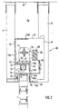
- FIGS. 1 and 2 The exemplary embodiment shown in FIGS. 1 and 2 is a two-leaf sliding door system with two motor-driven sliding door leaves 1, 2.
- the sliding door leaves 1, 2 are designed as oppositely driven moving leaves.
- the sliding door system forms a fire protection seal, in the case shown a fire protection and smoke protection seal.
- the sliding door leaves 1, 2 are designed as fire protection door leaves.
- the door leaves are modified for use as sliding door leaves.
- essential structural elements and materials of the proven fire protection constructions are used.
- the door leaves can be made of wood, metal, composite, glass in a so-called G or F version or a combination thereof.
- G or F version or a combination thereof.
- Around the door leaves intumizing sealing materials can be attached over the entire circumference. In the event of a fire, these are foaming materials or similar volume-increasing materials.
- additional step-like designs are formed on the sealing edges of the door leaves in a manner similar to that of overlapping swing door leaves in order to obtain a tight seal in the closed position.
- the abutting wing edges are preferably designed to complement each other.
- the end edges on the wall or frame side can be designed accordingly, so that in the closed position Door leaf a tight seal is guaranteed.
- Intumizing materials are preferably provided in the region of the edges lying in the closed position.
- the sliding door leaves 1, 2 are guided on upper rollers 3 in a fixedly mounted running tube 4.
- the rollers 3 are mounted in roller carriages 13 which are connected to the sliding sashes 1 and 2 by means of suspension screws.
- each wing 1, 2 carries two roller carriages 13.
- the structure of the roller carriage 13 and the basic structure of the running tube 4 corresponds to DE-OS 36 02 440.
- the running rollers are either completely made of metal or of metal with plastic running surfaces . However, they can alternatively also consist of other heat-resistant materials.
- a DC electric motor 5 with an electronic control device 50 is provided for the motorized drive of the sliding leaves 1, 2.
- the electrical supply lines, such as cables, etc., the motor 5 and the control device 50 can have additional thermal protection, for example by means of appropriate heat and fire-resistant casing.
- All drive units are installed above the running tube 4 in a smoke-tightly encapsulated receiving space 6 which is enclosed on all sides.
- the space 6 is formed in a so-called drive case 60, which extends from the upper edge of the sliding sash 1, 2 to the ceiling 61 and is covered on the outside at the front and rear by vertical wall elements 7, 8.
- the front wall element 7 is a sheet metal body which is rectangular in cross section
- the rear wall element 8 is a sheet metal panel which is angled downwards.
- the space 6 is delimited upwards and downwards by means of sheets and plates and profile angles which are fastened to flanges of the running tube 4.
- space 6 is delimited by wall elements on the face side.
- Both the drive case 60 and the wall elements 7, 8 are heat and fire resistant, for example by means of corresponding coatings or cladding applied inside or outside.
- Commercially available fire protection materials such as bromate, Fermazell, Ri-Gips z. B. can be used as cladding.
- at least the outer walls of the drive case 60 and the wall elements 7, 8 themselves can also be made of these materials consist. Foaming foils can also be applied for fire protection.
- the DC electric motor 5 with the electronic control device 50 and the other units of the drive are mounted on a common mounting flange 51.
- the flange 51 rests on the top of the running tube 4 and is clamped there.
- the running tube 4 has an upper horizontal flange 41 which protrudes on the front and rear sides of the running tube and has a horizontal groove 42 for clamping the drive unit.
- the mounting flange 51 resting on the flange 41 engages with a complementary foot 52 in the groove 42.
- the clamping connection is obtained via vertical clamping screws which engage in the area of the foot 52 and the groove 42.
- the motor 5 drives a drive belt-like element 55, which is arranged circumferentially on two deflection rollers 56, 57.
- the element 55 can be designed as a toothed belt made of heat-resistant material. Preferably a steel cable, e.g. B. Bowden cable used. However, a metal band or the like can also be used.
- essentially C-shaped drivers 58, 59 are provided for driving connection of the sliding sash 1, 2 with the drive belt-like element 55.
- the driver 58 is firmly connected with its upper leg to the upper run of the belt 55 and with its lower leg to the upper edge of the sliding leaf 2.
- the driver 59 is connected in a corresponding manner to the lower run of the belt 55 and to the upper edge of the sliding leaf 1. This means that the wings 1, 2 can only be moved simultaneously in opposite directions.
- the deflection roller 56 sits directly on the output shaft 5a of the electric motor 5.
- the deflection roller 57 is mounted on a separate bearing block 57a which, like the other drive units, is arranged and fastened on the horizontal flange 41 of the running rail housing 4.
- the bearing block 57a is not fastened on the fastening flange 51 of the drive unit, but is fastened separately via a corresponding, shorter fastening flange of its own.
- the running tube 4 with its molded flanges is designed as a hollow chamber profile.
- the hollow chamber forms the box-shaped running tube in which the carriages are guided.
- the horizontal flange 41 formed on the upper side of the running tube is angled perpendicularly at the front and downwards at the rear.
- An L-shaped bracket 42 is attached to the upward-pointing leg 41o, the upper leg 42o of which is horizontally arranged at a distance above the drive units to point to the rear.
- the upper horizontal plate 43 is screwed to this leg. It is cantilevered on the leg 42o.
- the downward leg 41u of the horizontal flange 41 ends vertically at approximately the same height as the lower edge of the box-shaped running tube.
- a vertical plate 44 is screwed to the leg 41u, the lower horizontal edge of which is at the same height as the lower horizontal edges of the covers 7 and 8.
- An L-shaped profile 45 is screwed to the lower edge of the plate 44, the horizontal of which lower leg 45u is directed towards the cover 8 and to which the lower horizontal cover plate 46 is screwed.
- This sheet 46 lies on the leg 45u and on the lower angled edge of the cover 8.
- the space 6 already described, which all drive units, d. H. Drive motor 5, control unit 50, drive belt 55, deflection rollers 56, 57, etc., is limited by the following walls: front and rear covers 7, 8, upper and lower cover plates 43, 44 and flange 41, plate 44 and angle 42, 45 .
- a horizontal longitudinal slot 44s is formed in the vertical plate 44, which extends over the entire travel path of the catches 58, 59.
- This slot forms the only opening of the box-shaped space 6, which accommodates all drive units.
- the slot is sealed in a smoke-tight manner, for example by intumizing materials being applied to the slot edges.
- the runner 6 forms the supporting element of the system.
- the running rail 6 can be designed as a self-supporting carrier. However, a separate, self-supporting carrier can also be provided, to which the running tube 4 is attached. Alternatively, the wall elements 7 and / or 8 can also be designed as load-bearing walls to which the running tube 4 is attached.
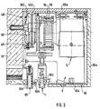
- the drive is attached to a vertical wall 70.
- a C-shaped running profile 400 open to one side is used, which has a lower running surface 401 and an upper running surface 402 on which the lower supporting rollers 301 and the upper supporting rollers 302 run.
- the rollers are made of heat-resistant material as in the previous embodiment.
- the drive in FIG. 3 has corresponding drive units as in FIGS. 1 and 2, namely a drive motor 5, a control device (not shown in FIG. 3) and a transmission belt-like transmission device between the driven side of the motor and the sliding sashes.
- All drive units including the running gear with the rollers and the running rail are arranged in a drive case 60.
- the drive case 60 is in the same way as in the embodiment described above heat and fire resistant and smoke-tight, for. B. with a heat-resistant cover 60a and intumizing seals 60d.
- fixed field leaves 101 and 102 are also provided, which can be attached in a conventional manner to the running rail 400 or to the wall 70 in a conventional manner.
- the sliding door systems can also be designed only as smoke protection closures. This means that only the measures are necessary that form a smoke-tight seal when the door is closed.
- a conventional sliding door system can be used, which is modified by special measures as a fire protection and / or smoke protection closure.
- Self-supporting constructions with a self-supporting beam possibly also with a self-supporting running rail, can also be used here, all the transitions between the building wall and the sliding sashes, in particular in the area of the drive case 60, being made fire-resistant or smoke-proof.
- Automatically moving seals can also be used, which can be controlled via corresponding contacts, preferably through contacts on the sliding leaves or corresponding fixed contacts or contacts arranged in the drive case, which are moved automatically in the closed position of the door in the sealing position. They can also be switched in such a way that they are only moved into the operative position in the event of a fire.
- the fire protection sliding door system in Fig. 4 is mounted in a facade construction and in a mullion-transom construction. This consists of vertical beams called posts and horizontal beams called rules.
- the drive unit 60 is fastened to the bolt 81, in which it is screwed there to the drive, specifically to the running rail 4.
- the sliding wings 1, 2 are guided in the drive 4.
- the drive unit which has the drive 4 and an electric drive motor and control devices, forms a composite cuboid body 60 which has a particularly low overall height. This vertical height corresponds to that of the latch 81.
- the drive unit is 7 cm and the latch 6 cm high.
- the facade has large glass panes 82 which are clamped between the posts and transoms.
- the sliding sash 1, 2 consist of glass panes 91 with a profile frame 92.
- the posts, the latches 81 and the frame 92 of the sliding sash 1, 2 are each formed from a profile. These are hollow profiles into which insulators 100 are inserted in order to obtain a fire-retardant effect.
- the insulators are heat-resistant profile material.
- Conventional profiles, for example aluminum profiles, can be used for the mullions, transoms and casement frames, as are conventionally used for facades and door frames without insulators. Profiles that are used in fire protection revolving door closures can preferably also be used.
- the vertical door plane of the sliding sash is offset from the vertical facade plane in the horizontal direction inside or outwards by the offset 99. This results from the fact that the drive 4 is arranged on the inside of the latch 81.
- a profile construction 95 which surrounds the door opening area on three sides is arranged in the door opening area.
- This profile construction has an upper horizontal upper profile part and two lateral vertical profile parts. The top of the upper horizontal profile part is attached to the underside of the bolt 81, preferably by a snap-in connector 95 a.
- the vertical profile parts are attached to vertical components of the facade construction or to fixed field wings of the sliding door system.
- the profile structure 95 is arranged so that it covers the offset 99 between the door level of the wings 1, 2 and the facade level, i.e. it extends with its side facing the sliding sashes up to close to the door plane of the sliding sash, preferably up to can be arranged in front of the profile frame 92 of the sliding sash. It engages under the drive box 60 in the area of the drive 4 and covers the offset 99 between the wing and facade.
- Insulators 100 are also inserted into the profiles of the profile structure 95, so that the passage of heat and fire is prevented.
- the drive box 60 can also with insulating material such. B. panels outside or inside and so in addition or instead of the profile construction 95 shut off the offset 99 against fire penetration.
- the isolators 100 can be located on the entire box or only on a part of the box, e.g. only in the area of the offset.
- the individual drive units can be protected against fire by appropriate formwork or encapsulation, in particular the locking unit, which performs the emergency closing in the event of a fire.
- electrical supply lines, etc. can also be appropriately coated or heat-resistant.
- the drive, in particular the rollers, can also be heat-resistant, so that the emergency closing can still be guaranteed even in the event of a fire.
Landscapes
- Engineering & Computer Science (AREA)
- Civil Engineering (AREA)
- Structural Engineering (AREA)
- Special Wing (AREA)
- Power-Operated Mechanisms For Wings (AREA)
Applications Claiming Priority (2)
| Application Number | Priority Date | Filing Date | Title |
|---|---|---|---|
| DE19607967A DE19607967A1 (de) | 1996-03-01 | 1996-03-01 | Schiebetüranlage |
| DE19607967 | 1996-03-01 |
Publications (3)
| Publication Number | Publication Date |
|---|---|
| EP0798441A2 true EP0798441A2 (fr) | 1997-10-01 |
| EP0798441A3 EP0798441A3 (fr) | 1999-06-09 |
| EP0798441B1 EP0798441B1 (fr) | 2003-08-20 |
Family
ID=7786966
Family Applications (1)
| Application Number | Title | Priority Date | Filing Date |
|---|---|---|---|
| EP97103358A Expired - Lifetime EP0798441B1 (fr) | 1996-03-01 | 1997-02-28 | Ensemble de porte coulissante coupe-feu |
Country Status (3)
| Country | Link |
|---|---|
| EP (1) | EP0798441B1 (fr) |
| AT (1) | ATE247760T1 (fr) |
| DE (2) | DE19607967A1 (fr) |
Cited By (4)
| Publication number | Priority date | Publication date | Assignee | Title |
|---|---|---|---|---|
| WO2001069028A1 (fr) * | 2000-03-15 | 2001-09-20 | Marioff Corporation Oy | Porte coupe-feu et systeme de protection contre le feu |
| EP1359280A3 (fr) * | 2002-04-16 | 2005-06-01 | DORMA GmbH + Co. KG | Ensemble de porte coulissante |
| EP3034767B1 (fr) | 2014-12-18 | 2017-11-01 | dormakaba Deutschland GmbH | Système de paroi coulissante |
| CN113323536A (zh) * | 2021-04-27 | 2021-08-31 | 深圳市比斯特科技材料有限公司 | 一种自动平移门驱动装置及其使用方法 |
Families Citing this family (5)
| Publication number | Priority date | Publication date | Assignee | Title |
|---|---|---|---|---|
| DE19817440B4 (de) * | 1997-04-18 | 2011-12-29 | Geze Gmbh | Schiebetüranlage |
| DE19753132C5 (de) * | 1997-11-29 | 2010-05-20 | Geze Gmbh | Brandschutzschiebetüranlage |
| FR2951490B1 (fr) * | 2009-10-21 | 2011-11-11 | Mineur Becourt Systemes | Porte coulissante coupe-feu motorisee n2 |
| DE102014114351A1 (de) | 2014-10-02 | 2016-04-07 | Hörmann KG Eckelhausen | Brandschutztür und betriebsverfahren hierfür |
| DE102018125925A1 (de) | 2018-10-18 | 2020-04-23 | Novoferm Riexinger Türenwerke GmbH | Brandschutzschiebetor |
Family Cites Families (4)
| Publication number | Priority date | Publication date | Assignee | Title |
|---|---|---|---|---|
| DE3212640A1 (de) * | 1982-04-05 | 1983-10-13 | Türenwerke Riexinger GmbH & Co KG, 7129 Brackenheim | Schiebetor, schiebetuer oder dergleichen |
| US4467562A (en) * | 1982-09-15 | 1984-08-28 | American Metal Door Company, Inc. | Fire door assembly |
| DE3602567C2 (de) * | 1986-01-29 | 1994-05-26 | Geze Grundstueck Beteiligung | Schiebetürantrieb |
| FR2700186B1 (fr) * | 1993-01-05 | 1995-03-24 | Fichet Bauche | Porte automatique à plusieurs vantaux télescopiques. |
-
1996
- 1996-03-01 DE DE19607967A patent/DE19607967A1/de not_active Withdrawn
-
1997
- 1997-02-28 DE DE59710594T patent/DE59710594D1/de not_active Expired - Lifetime
- 1997-02-28 AT AT97103358T patent/ATE247760T1/de not_active IP Right Cessation
- 1997-02-28 EP EP97103358A patent/EP0798441B1/fr not_active Expired - Lifetime
Cited By (7)
| Publication number | Priority date | Publication date | Assignee | Title |
|---|---|---|---|---|
| WO2001069028A1 (fr) * | 2000-03-15 | 2001-09-20 | Marioff Corporation Oy | Porte coupe-feu et systeme de protection contre le feu |
| US6779309B2 (en) | 2000-03-15 | 2004-08-24 | Marioff Corporation Oy | Door actuator for cooling a fire door |
| RU2268346C2 (ru) * | 2000-03-15 | 2006-01-20 | Мариофф Корпорейшн Ой | Противопожарная дверь и система противопожарной защиты |
| EP1359280A3 (fr) * | 2002-04-16 | 2005-06-01 | DORMA GmbH + Co. KG | Ensemble de porte coulissante |
| US6973753B2 (en) | 2002-04-16 | 2005-12-13 | Dorma Gmbh + Co. Kg | Sliding door system |
| EP3034767B1 (fr) | 2014-12-18 | 2017-11-01 | dormakaba Deutschland GmbH | Système de paroi coulissante |
| CN113323536A (zh) * | 2021-04-27 | 2021-08-31 | 深圳市比斯特科技材料有限公司 | 一种自动平移门驱动装置及其使用方法 |
Also Published As
| Publication number | Publication date |
|---|---|
| ATE247760T1 (de) | 2003-09-15 |
| EP0798441A3 (fr) | 1999-06-09 |
| DE59710594D1 (de) | 2003-09-25 |
| EP0798441B1 (fr) | 2003-08-20 |
| DE19607967A1 (de) | 1997-09-04 |
Similar Documents
| Publication | Publication Date | Title |
|---|---|---|
| EP0882169B1 (fr) | Porte coupe-feu | |
| EP0785334B2 (fr) | Elément de construction coupe-feu | |
| DE19733393B4 (de) | Glasflügel, insbesondere für Türen, Fenster, Festfelder oder als Fassadenelement | |
| EP0822310B1 (fr) | Porte glissante | |
| EP0549769B1 (fr) | Cloison ignifuge en verre | |
| EP3221540A1 (fr) | Dispositif d'étanchéité pour châssis mobile utilisé comme châssis coulissant ou châssis levant-coulissant mobile d'une fenêtre ou d'une porte | |
| EP2581515A1 (fr) | Partition coupe feu en panneaux de verre avec porte | |
| DE19753132B4 (de) | Brandschutzschiebetüranlage | |
| EP0658662B1 (fr) | Façade vitrée avec fenêtre | |
| EP0798441B1 (fr) | Ensemble de porte coulissante coupe-feu | |
| EP2857626B1 (fr) | Porte inhibant l'effraction ou fenêtre inhibant l'effraction | |
| DE3803317A1 (de) | Feuerschutz-fahrstuhltuer | |
| AT394881B (de) | Sektionaltor | |
| EP1427907B1 (fr) | Systeme de cloison coulissante avec un element de battant de porte coulissant et pivotant | |
| EP2657012B1 (fr) | Porte anti-incendie entièrement en verre sans cadre | |
| EP2581534B1 (fr) | Dispositif de retenue par serrage | |
| DE19817440B4 (de) | Schiebetüranlage | |
| EP2204525B1 (fr) | Porte coulissante et tournante et applications anti-incendie | |
| EP0828913B1 (fr) | Systeme de protection contre les cambriolages | |
| EP4509686B1 (fr) | Porte à deux battants, fenêtre à deux battants ou porte-fenetre à deux battants | |
| EP2302154A2 (fr) | Régulation de fermeture pour une porte pivotante et coulissante, notamment pour des applications anti-incendie | |
| EP4446550A1 (fr) | Fenêtre d'angle ou porte d'angle avec vantaux coulissants, pouvant être déplacés parallèlement à un cadre fixe | |
| EP3604726A1 (fr) | Cadre de porte ou porte | |
| WO2006128418A2 (fr) | Dispositif pour securiser des fenetres et des portes | |
| CH653405A5 (en) | Insulating screening device on external wall openings |
Legal Events
| Date | Code | Title | Description |
|---|---|---|---|
| PUAI | Public reference made under article 153(3) epc to a published international application that has entered the european phase |
Free format text: ORIGINAL CODE: 0009012 |
|
| AK | Designated contracting states |
Kind code of ref document: A2 Designated state(s): AT BE CH DE DK ES FR GB GR IE IT LI LU MC NL PT SE |
|
| AX | Request for extension of the european patent |
Free format text: LT PAYMENT 970325;LV PAYMENT 970325;SI PAYMENT 970325 |
|
| PUAL | Search report despatched |
Free format text: ORIGINAL CODE: 0009013 |
|
| AK | Designated contracting states |
Kind code of ref document: A3 Designated state(s): AT BE CH DE DK ES FR GB GR IE IT LI LU MC NL PT SE |
|
| AX | Request for extension of the european patent |
Free format text: LT PAYMENT 19970325;LV PAYMENT 19970325;SI PAYMENT 19970325 |
|
| RIC1 | Information provided on ipc code assigned before grant |
Free format text: 6E 05D 15/06 A, 6E 06B 5/16 B |
|
| 17P | Request for examination filed |
Effective date: 19990703 |
|
| RAP1 | Party data changed (applicant data changed or rights of an application transferred) |
Owner name: GEZE GMBH |
|
| RAP3 | Party data changed (applicant data changed or rights of an application transferred) |
Owner name: GEZE GMBH |
|
| 17Q | First examination report despatched |
Effective date: 20010425 |
|
| GRAH | Despatch of communication of intention to grant a patent |
Free format text: ORIGINAL CODE: EPIDOS IGRA |
|
| GRAH | Despatch of communication of intention to grant a patent |
Free format text: ORIGINAL CODE: EPIDOS IGRA |
|
| GRAH | Despatch of communication of intention to grant a patent |
Free format text: ORIGINAL CODE: EPIDOS IGRA |
|
| GRAA | (expected) grant |
Free format text: ORIGINAL CODE: 0009210 |
|
| AK | Designated contracting states |
Designated state(s): AT BE CH DE DK ES FR GB GR IE IT LI LU MC NL PT SE |
|
| AX | Request for extension of the european patent |
Extension state: LT LV SI |
|
| PG25 | Lapsed in a contracting state [announced via postgrant information from national office to epo] |
Ref country code: NL Free format text: LAPSE BECAUSE OF FAILURE TO SUBMIT A TRANSLATION OF THE DESCRIPTION OR TO PAY THE FEE WITHIN THE PRESCRIBED TIME-LIMIT Effective date: 20030820 Ref country code: IT Free format text: LAPSE BECAUSE OF FAILURE TO SUBMIT A TRANSLATION OF THE DESCRIPTION OR TO PAY THE FEE WITHIN THE PRESCRIBED TIME-LIMIT;WARNING: LAPSES OF ITALIAN PATENTS WITH EFFECTIVE DATE BEFORE 2007 MAY HAVE OCCURRED AT ANY TIME BEFORE 2007. THE CORRECT EFFECTIVE DATE MAY BE DIFFERENT FROM THE ONE RECORDED. Effective date: 20030820 Ref country code: IE Free format text: LAPSE BECAUSE OF FAILURE TO SUBMIT A TRANSLATION OF THE DESCRIPTION OR TO PAY THE FEE WITHIN THE PRESCRIBED TIME-LIMIT Effective date: 20030820 Ref country code: GB Free format text: LAPSE BECAUSE OF FAILURE TO SUBMIT A TRANSLATION OF THE DESCRIPTION OR TO PAY THE FEE WITHIN THE PRESCRIBED TIME-LIMIT Effective date: 20030820 Ref country code: FR Free format text: LAPSE BECAUSE OF FAILURE TO SUBMIT A TRANSLATION OF THE DESCRIPTION OR TO PAY THE FEE WITHIN THE PRESCRIBED TIME-LIMIT Effective date: 20030820 Ref country code: ES Free format text: LAPSE BECAUSE OF FAILURE TO SUBMIT A TRANSLATION OF THE DESCRIPTION OR TO PAY THE FEE WITHIN THE PRESCRIBED TIME-LIMIT Effective date: 20030820 |
|
| REG | Reference to a national code |
Ref country code: GB Ref legal event code: FG4D Free format text: NOT ENGLISH |
|
| REG | Reference to a national code |
Ref country code: CH Ref legal event code: EP |
|
| REG | Reference to a national code |
Ref country code: IE Ref legal event code: FG4D Free format text: GERMAN |
|
| REF | Corresponds to: |
Ref document number: 59710594 Country of ref document: DE Date of ref document: 20030925 Kind code of ref document: P |
|
| PG25 | Lapsed in a contracting state [announced via postgrant information from national office to epo] |
Ref country code: SE Free format text: LAPSE BECAUSE OF FAILURE TO SUBMIT A TRANSLATION OF THE DESCRIPTION OR TO PAY THE FEE WITHIN THE PRESCRIBED TIME-LIMIT Effective date: 20031120 Ref country code: GR Free format text: LAPSE BECAUSE OF FAILURE TO SUBMIT A TRANSLATION OF THE DESCRIPTION OR TO PAY THE FEE WITHIN THE PRESCRIBED TIME-LIMIT Effective date: 20031120 Ref country code: DK Free format text: LAPSE BECAUSE OF FAILURE TO SUBMIT A TRANSLATION OF THE DESCRIPTION OR TO PAY THE FEE WITHIN THE PRESCRIBED TIME-LIMIT Effective date: 20031120 |
|
| PG25 | Lapsed in a contracting state [announced via postgrant information from national office to epo] |
Ref country code: PT Free format text: LAPSE BECAUSE OF FAILURE TO SUBMIT A TRANSLATION OF THE DESCRIPTION OR TO PAY THE FEE WITHIN THE PRESCRIBED TIME-LIMIT Effective date: 20040120 |
|
| LTIE | Lt: invalidation of european patent or patent extension |
Effective date: 20030820 |
|
| NLV1 | Nl: lapsed or annulled due to failure to fulfill the requirements of art. 29p and 29m of the patents act | ||
| GBV | Gb: ep patent (uk) treated as always having been void in accordance with gb section 77(7)/1977 [no translation filed] |
Effective date: 20030820 |
|
| PG25 | Lapsed in a contracting state [announced via postgrant information from national office to epo] |
Ref country code: MC Free format text: LAPSE BECAUSE OF NON-PAYMENT OF DUE FEES Effective date: 20040228 Ref country code: LU Free format text: LAPSE BECAUSE OF NON-PAYMENT OF DUE FEES Effective date: 20040228 Ref country code: BE Free format text: LAPSE BECAUSE OF NON-PAYMENT OF DUE FEES Effective date: 20040228 Ref country code: AT Free format text: LAPSE BECAUSE OF NON-PAYMENT OF DUE FEES Effective date: 20040228 |
|
| PG25 | Lapsed in a contracting state [announced via postgrant information from national office to epo] |
Ref country code: LI Free format text: LAPSE BECAUSE OF NON-PAYMENT OF DUE FEES Effective date: 20040229 Ref country code: CH Free format text: LAPSE BECAUSE OF NON-PAYMENT OF DUE FEES Effective date: 20040229 |
|
| REG | Reference to a national code |
Ref country code: IE Ref legal event code: FD4D |
|
| PLBE | No opposition filed within time limit |
Free format text: ORIGINAL CODE: 0009261 |
|
| STAA | Information on the status of an ep patent application or granted ep patent |
Free format text: STATUS: NO OPPOSITION FILED WITHIN TIME LIMIT |
|
| 26N | No opposition filed |
Effective date: 20040524 |
|
| BERE | Be: lapsed |
Owner name: *GEZE G.M.B.H. Effective date: 20040228 |
|
| EN | Fr: translation not filed | ||
| REG | Reference to a national code |
Ref country code: CH Ref legal event code: PL |
|
| PGFP | Annual fee paid to national office [announced via postgrant information from national office to epo] |
Ref country code: DE Payment date: 20150228 Year of fee payment: 19 |
|
| REG | Reference to a national code |
Ref country code: DE Ref legal event code: R231 Ref document number: 59710594 Country of ref document: DE |
|
| PG25 | Lapsed in a contracting state [announced via postgrant information from national office to epo] |
Ref country code: DE Free format text: LAPSE BECAUSE OF THE APPLICANT RENOUNCES Effective date: 20151219 |