EP0798552A1 - Détecteur de gaz photoacoustique - Google Patents
Détecteur de gaz photoacoustique Download PDFInfo
- Publication number
- EP0798552A1 EP0798552A1 EP97104373A EP97104373A EP0798552A1 EP 0798552 A1 EP0798552 A1 EP 0798552A1 EP 97104373 A EP97104373 A EP 97104373A EP 97104373 A EP97104373 A EP 97104373A EP 0798552 A1 EP0798552 A1 EP 0798552A1
- Authority
- EP
- European Patent Office
- Prior art keywords
- microphone
- gas sensor
- monitoring
- heating element
- signal
- Prior art date
- Legal status (The legal status is an assumption and is not a legal conclusion. Google has not performed a legal analysis and makes no representation as to the accuracy of the status listed.)
- Granted
Links
- 238000010438 heat treatment Methods 0.000 claims abstract description 65
- 239000012528 membrane Substances 0.000 claims abstract description 28
- 230000035945 sensitivity Effects 0.000 claims abstract description 26
- 238000000034 method Methods 0.000 claims abstract description 12
- 230000007547 defect Effects 0.000 claims abstract description 7
- 239000007789 gas Substances 0.000 claims description 73
- 238000012544 monitoring process Methods 0.000 claims description 46
- 238000011156 evaluation Methods 0.000 claims description 12
- 239000000463 material Substances 0.000 claims description 7
- 230000003321 amplification Effects 0.000 claims description 4
- 230000007774 longterm Effects 0.000 claims description 4
- 238000003199 nucleic acid amplification method Methods 0.000 claims description 4
- 238000001514 detection method Methods 0.000 claims description 3
- 239000011888 foil Substances 0.000 claims description 3
- 238000012545 processing Methods 0.000 claims description 3
- 238000001914 filtration Methods 0.000 claims description 2
- 229910001006 Constantan Inorganic materials 0.000 claims 1
- 238000004880 explosion Methods 0.000 abstract description 2
- 210000004027 cell Anatomy 0.000 description 20
- 238000012806 monitoring device Methods 0.000 description 11
- 230000010363 phase shift Effects 0.000 description 5
- 230000002950 deficient Effects 0.000 description 4
- 230000003287 optical effect Effects 0.000 description 4
- 239000000853 adhesive Substances 0.000 description 2
- 230000001070 adhesive effect Effects 0.000 description 2
- 238000004519 manufacturing process Methods 0.000 description 2
- 230000001105 regulatory effect Effects 0.000 description 2
- 230000003595 spectral effect Effects 0.000 description 2
- SNICXCGAKADSCV-JTQLQIEISA-N (-)-Nicotine Chemical compound CN1CCC[C@H]1C1=CC=CN=C1 SNICXCGAKADSCV-JTQLQIEISA-N 0.000 description 1
- 238000010521 absorption reaction Methods 0.000 description 1
- 210000002421 cell wall Anatomy 0.000 description 1
- 230000001419 dependent effect Effects 0.000 description 1
- 230000000694 effects Effects 0.000 description 1
- 230000031700 light absorption Effects 0.000 description 1
- 230000007257 malfunction Effects 0.000 description 1
- 238000005259 measurement Methods 0.000 description 1
- 229960002715 nicotine Drugs 0.000 description 1
- SNICXCGAKADSCV-UHFFFAOYSA-N nicotine Natural products CN1CCCC1C1=CC=CN=C1 SNICXCGAKADSCV-UHFFFAOYSA-N 0.000 description 1
- 239000012811 non-conductive material Substances 0.000 description 1
- 238000005457 optimization Methods 0.000 description 1
- 229920000515 polycarbonate Polymers 0.000 description 1
- 239000004417 polycarbonate Substances 0.000 description 1
- 238000011160 research Methods 0.000 description 1
- 229910000679 solder Inorganic materials 0.000 description 1
- 230000001360 synchronised effect Effects 0.000 description 1
- 230000002123 temporal effect Effects 0.000 description 1
Images
Classifications
-
- G—PHYSICS
- G01—MEASURING; TESTING
- G01N—INVESTIGATING OR ANALYSING MATERIALS BY DETERMINING THEIR CHEMICAL OR PHYSICAL PROPERTIES
- G01N21/00—Investigating or analysing materials by the use of optical means, i.e. using sub-millimetre waves, infrared, visible or ultraviolet light
- G01N21/17—Systems in which incident light is modified in accordance with the properties of the material investigated
- G01N21/1702—Systems in which incident light is modified in accordance with the properties of the material investigated with opto-acoustic detection, e.g. for gases or analysing solids
Definitions
- the invention relates to a photoacoustic gas sensor with an explosion-proof, active device for monitoring the functionality of its components and calibration of its sensitivity, and a method for evaluating the output signals of the device.
- Photoacoustic gas sensors are used in research and industry to determine the concentration of certain predominant gases. Their areas of application are, for example, the monitoring of processes in bioreactors or breweries and of gas concentrations in laboratories and other work rooms in order to maintain the maximum workplace concentrations (MAK). They determine the presence and concentration of a gas and emit an alarm or warning signal when a predetermined concentration is exceeded.
- MAK maximum workplace concentrations
- Photoacoustic gas sensors used today typically consist of a measuring cell with a gas-permeable membrane, a pulsed light source, a photodiode, a microphone and an electrical circuit for operating the light source and the microphone and for Evaluation of the microphone output signal.
- the light source sends light pulses into the measuring cell that have a wavelength that are absorbed by the gas to be detected.
- narrowband light sources such as light emitting diodes and lasers
- broadband light sources such as incandescent filaments are used together with an optical bandpass filter.
- the photodiode is used to measure the intensity of the light pulses, the signals resulting from it being used to regulate the operating voltage of the light source and to maintain a stable light intensity. If a gas to be detected is in the vicinity of the gas sensor, it penetrates through the gas-permeable membrane into the measuring cell and absorbs the incident light there. The absorption of the light pulses causes the gas in the measuring cell to heat up and expand, producing pressure modulation which is received by the microphone and converted into an electrical signal. The output signal of the microphone is amplified by an evaluation circuit and compared with gas concentration values which were stored in an EEPROM when the sensor was calibrated. The concentration of the detected gas is determined on the basis of the stored calibration values and, if necessary, a warning or alarm signal is issued.
- the gas sensor of the above-mentioned application has a passive monitoring of the functionality of the microphone and other of its components by means of a background signal of the microphone output signal, which results from the heating of parts of the measuring cell by light absorption. If the microphone is defective or the membrane has a small hole, the background signal becomes smaller. However, the method does not allow to determine whether the microphone is still fully sensitive or whether its sensitivity has dropped. If the sensitivity of the microphone has dropped, for example due to drift over a longer period of time or due to a sudden defect, its initial values are assigned to incorrect gas concentrations and a gas alarm may not be reported.
- the background signal is of different sizes depending on the wavelength of the light pulses that reach the measuring cell and, at certain wavelengths, is almost zero, which makes evaluation of the background signal difficult.
- Another method is to monitor the noise of the microphone. If this noise disappears, this is an indication that the microphone is no longer working properly. On the other hand, the presence of noise is not a clear indication of an intact microphone.
- a microphone noise is pretended when the membrane is also defective and a noise is caused by external pressure fluctuations, which is superimposed on the greatly reduced noise of the defective microphone. A defect in the membrane and in the microphone can therefore be misinterpreted.
- these monitoring methods based on background signal and noise are based on passive effects that are not controlled directly by the circuit.
- the object of the invention is to provide a photoacoustic gas sensor of the type mentioned above, which has an active device for monitoring the functionality of the gas-permeable membrane and the microphone, and a method for evaluating the output signals of the monitoring device for detection the functional state of the microphone and the membrane and for calibration of the microphone sensitivity and a method for operating the monitoring device.
- the operation of this monitoring device should be explosion-proof.
- a photoacoustic gas sensor of the type mentioned above which contains a device for monitoring the functionality of the microphone and the membrane and carrying out a calibration of the microphone sensitivity, the device for actively generating an artificial pressure modulation in the measuring cell, which is carried out by the microphone electrical monitoring signals are converted, and has a circuit for operating this device, for processing and evaluating the monitoring signals and calibrating the microphone sensitivity.
- This device preferably consists of an electrical heating element for modulated heating of the air, such as a wire, a resistor, a heating foil.
- the microphone housing is also suitable for this heating.
- the modulated heating of the air, provided that the membrane does not leak has, an artificial pressure modulation generated, which does not result from the presence of a gas in the measuring cell of the gas sensor.
- the microphone If the microphone is also functional, it generates an electrical signal when the pressure modulation is received, which is amplified and evaluated by the circuit.
- the functionality of the membrane and the microphone is inferred on the basis of the resulting monitoring signal and, if necessary, calibration of the microphone sensitivity is carried out, the size and the temporal change in the monitoring signal being evaluated.
- the size of the resulting monitoring signal is assigned to one of several different areas. If the size of the monitoring signal falls within a predetermined positive range, the circuit emits a message which indicates that both the membrane and the microphone are functioning correctly. If the monitoring signal falls in a higher or lower range compared to the first predetermined range, a microprocessor calibrates the microphone sensitivity by recalculating the gas concentration values based on the determined microphone sensitivity and storing them in an EEPROM.
- the circuit issues a fault message, which indicates that either there is no pressure modulation in the measuring cell due to a leaky membrane, the sensitivity of the microphone has dropped to zero and / or the heating element is defective is.
- the explosion protection of the monitoring device is guaranteed by the fact that the current flowing through the heating element and the maximum temperatures reached by the heating element and the components of the circuit meet safety requirements, such as those according to the Euronorm EN 50020: 1994, which are approved by the Physikalische Technische Bundesweg Braunschweig ( PTB) are checked.
- the wire as a heating element, this is achieved through a suitable choice of the material and the dimensions of the wire.
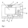
- Figure 1 shows a photoacoustic gas sensor in cross section with a device for heating the air in the measuring cell.
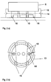
- Figures 2 a) and b) show an embodiment of an electrical heating element for heating the air in the measuring cell and the assembly of an electrically heatable wire as a heating element.
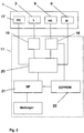
- FIG. 3 shows a schematic structure of the circuit for operating the monitoring device of the gas sensor and evaluating the output signals of the microphone.
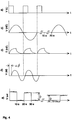
- FIG. 4 shows an example of a time profile for monitoring the gas sensor and calibrating the microphone sensitivity.
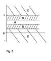
- FIG. 5 shows the various areas to which the monitoring signals are assigned for the purpose of their evaluation.
- Figure 1 shows a photoacoustic gas sensor 1 in cross section with a measuring cell 2, a lamp 3 with a filament 4 as a light source and an optical bandpass filter 5, a microphone 6 and a gas permeable membrane 7, which lies on a perforated grid 8 and with adhesive with the measuring cell wall is tightly connected.
- a photodiode for monitoring the light intensity is not shown here.
- Broadband light pulses emanate from the filament 4 and, after spectral filtering at the bandpass filter 5, emit the measuring cell 2.
- the optical bandpass filter 5 is transparent in a narrow spectral range around the wavelength of 4.26 ⁇ m, which is absorbed by CO 2 gas.
- the gas sensor 1 has a heating element 9 which is arranged at any location in the interior of the measuring cell 2. It is preferably in the vicinity of the printed circuit board 10 with the circuit 11 for operating the gas sensor 1 and heating element 9 and for evaluating the output signals of the microphone 6.
- the heating element 9 preferably consists of a thin wire, although conventional and surface-mount Resistors and heating foils are suitable for this.
- Another embodiment of the device for heating the air is the electrical heating of the microphone housing.
- a modulated voltage is applied to the heating element 9, whereby it itself and the air in the measuring cell 2 are heated and the expansion of the air produces an artificial pressure modulation which is independent of the presence of gases to be detected.
- This pressure modulation is converted by the microphone 6 into an electrical signal, which is amplified and evaluated by the circuit 11, whereupon a message is issued which indicates whether the microphone 6 and the membrane 7 are working or the microphone sensitivity compared to the beginning of the operating time of the Gas sensor 1 has changed.
- the heating element 9 and the components of the circuit 11 and their operating parameters meet the requirements for explosion-proof operation according to the PTB.
- a heating element 9 with a corresponding resistance is therefore used, and if a wire is used, its diameter, length and material are matched to this resistance.
- the material is preferably one that is chemically stable and whose resistance changes as little as possible as a function of temperature, so that the heat output emitted by the wire is stable over a long period and is independent of the temperature. Examples of suitable materials are Nikrothal and Konstantan. If a material with a higher temperature coefficient of specific resistance is used instead, the choice of the parameters of the wire would be more difficult, since the voltage applied to the heating element would have to be regulated according to the wire temperature.
- a heating element that meets the above-mentioned conditions is a wire made of nikrothal with a diameter of 30 ⁇ m and a length of 1 cm, the resistance of which is 20 ⁇ . If a current of 0.6 mA flows through this wire at an applied voltage of 12 mV, it heats up by 2.5 ° C according to theoretical calculations, while the measured temperature increase of the wire is approx. 1 ° C.
- the parameters and the material of the wire can also be selected accordingly, so that only the requirements of temperature class T4 are met.
- FIGS. 2 a) and b) show in a cross section or a plan view an example of an assembly of a wire 12 as a heating element 9.
- the wire 12 is fastened on a cylindrical support 13 which is attached to the microphone 6 and fastened to the printed circuit board 10 with adhesive is.
- the microphone 6 is fastened on a shoulder.
- the cylindrical support also serves as a holder for the microphone 6.
- the wire is guided in a notch 14, so that it runs on the plane shown with the dashed line and does not move from it.
- the purpose of this is that there is an air space under and above the wire 12 and it is electrically insulated by not coming into contact with the wall of the measuring cell 2 and the microphone.
- the cylindrical support 13 is made of a non-conductive material, such as polycarbonate.
- the wire 12 is wound like a meander around several slots 15 on the upper edge of the cylindrical carrier 13. The ends of the wire 12 are guided through holes in the center of the cylindrical carrier 13 and soldered to solder points 16 on the printed circuit board 10.
- Figure 3 shows a schematic structure of the gas sensor 1 with monitoring device. It shows the electrical components of the gas sensor 1, the lamp L 3, the microphone M 6, the photodiode PD 17 and the heating element HE 9 and the circuit 11 for operating the gas sensor 1 and the monitoring device.
- the circuit 11 contains a first driver circuit 18 for the heating element 9 and a second driver circuit 19 for the lamp L 3.
- the electrical signals generated by the microphone M 6 on the basis of received pressure modulations are fed to an evaluation circuit 20, where they are linearly amplified by a high-pass filter. and low-pass filter cleaned and synchronized rectified and smoothed by a phase-sensitive rectifier will.
- the resulting DC signals are forwarded to a MP 21 microprocessor, which compares them with predetermined comparison values.
- the microprocessor MP 21 includes the change in the monitoring signal over time in the evaluation. In the case of a slow change, such as a change over several days, this is assessed as a long-term drift, and the microphone sensitivity is calibrated by tracking the values stored in the EEPROM 22 to determine the concentration values or gas concentration values in accordance with the change in the microphone sensitivity. This is done by determining the percentage change in the monitoring signals and changing the gas concentration values accordingly. This tracking of the microphone sensitivity corrects the long-term drift of the microphone.
- the microprocessor issues a message, for example an optical or acoustic signal which indicates a fault on the microphone and / or on the membrane indicates.
- the EEPROM 22 contains further operating data of the gas sensor such as counters, temperatures of the measuring gas, brightness values of the lamp 3 and phase values for the optimal amplification of the microphone signals.
- the temperatures of the measurement gas are determined by a temperature sensor contained in the microprocessor 20 and used by the microprocessor 21 for the recalculation of the temperature-dependent gas concentration values.
- the brightness values of the lamp 3 are fed from the photodiode 17 and the evaluation circuit 20 to the microprocessor 21 and used for regulating the light intensity of the lamp 3 by calculating the necessary pulse duration and feeding the driver circuit 19 for the lamp 3.
- the phase values are the phase differences between the voltage signal for the heating element 9 and the output signal of the microphone 6.
- the phase values are determined during the manufacture of the gas sensor 1 by optimizing the amplification of the output signal of the microphone 6 by entering the phase.
- the phase at which the microphone signal reaches a maximum is then stored in the EEPROM 22.
- the EEPROM 22 is a serial EEPROM with an integrated interface circuit bus (IIC bus). Thanks to this IIC bus, only one data line is required in addition to the clock line.
- the clock of the EEPROM also serves as a clock for the heating element 9 in that the clock signal is fed to the first driver circuit 18 for the heating element 9.
- FIG. 4 shows an example of a time profile of a monitoring of the gas sensor 1 as a function of the time t.
- Figure 4 a) shows the voltage pulses V (L) for the operation of the lamp 3. For example, it is operated at 14 Hz and a duty cycle of one third.
- a heating element for Heating of the measuring cell 2 is, as the modulated voltage V (HE) in Figure 4 b) show, operated at 7 Hz, the power curve having the clock frequency of 14 Hz.
- the voltage V (L) also serves to trigger the phase-sensitive rectifier of the evaluation circuit 20.
- a synchronization of the lamp 3 and the heating of the heating element 9 allows a simpler evaluation of the monitoring signals and gas signals with the same electrical components.
- the modulated voltage preferably has a sine function; a triangular or trapezoidal function or a function with any flanks are also suitable.
- FIG. 4 c) shows the approximate temperature curve T (HE) of a nicotine wire 2.5 cm long and 30 ⁇ m in diameter, through which a current of less than 1 mA flows according to FIG. 4 b).
- FIG. 4 d) shows a microphone signal V (M) generated by the microphone 6, in this case the monitoring signal resulting from the artificial heating of the measuring cell 2.
- the phase shift ⁇ of the generated signal with respect to the voltage for operating the lamp 3 is the phase determined during production by optimization of the microphone signal and stored in the EEPROM 22.
- microphone signals that are caused by the presence of detectable gases in the measuring cell are also amplified with this phase shift ⁇ .
- Figure 4 e shows the DC output signal Vout of the evaluation circuit 20 of the monitoring device over a long period of time.
- the monitoring device is switched on and off at a frequency of 1/10 Hz, which prevents the monitoring device from being in permanent operation.
- the monitoring signal is in each case an order of magnitude smaller than the signal that results from gas detection. It can therefore be distinguished with certainty from a gas alarm signal.
- the mean value of the signal difference D between the on and off state is determined. This mean value is the decisive variable of the monitoring signal and is assigned by the microprocessor 21 to the areas in FIG. 5.
- a preferred embodiment of the photoacoustic gas sensor has small dimensions.
- gas sensors of this type there is a problem of electrical crosstalk between the components, while in larger photoacoustic measuring devices these problems arise less because the components can be placed further apart there.
- the heating element is located very close to the microphone in a small gas sensor.
- the heating element and the microphone are connected to the same supply in order to save electrical components. This often causes electrical crosstalk between the heating element and the microphone, which causes interference signals on the microphone signal V (M).
- the operation of the photoacoustic gas sensor is similar to that shown in FIG. 4, but with an additional phase shift in the voltage for operating the heating element V (HE) and the resulting temperature profile T (HE) in FIGS.
- the voltage for the lamp V (L) in turn serves to trigger the phase-sensitive rectifier for the amplification of the microphone signal V (M).
- the microphone signal V (M) is amplified with the phase shift ⁇ with respect to V (L) in order to optimize the signal strength.
- the heating voltage for the heating element V (HE) is now shifted in its phase with respect to the microphone signal V (M).
- the phase shift is determined experimentally so that the electrical crosstalk drops to a minimum value. While the voltage for the heating element V (HE) is out of phase with respect to the microphone signal V (M), the monitoring signal artificially produced by the heating element is approximately in phase with the microphone signal V (M).
- thermal inertia of the wire for the heating element that has been specially selected for this application.
- the thermal inertia is chosen experimentally such that the temperature rise T (HE) and thus also the artificially produced monitoring signal is approximately in phase with the microphone signal V (M). If, for example, the monitoring signal and the microphone signal V (M) are only out of phase by 30 °, the electrical crosstalk is zero, the monitoring signal reaching 85% of its maximum value.
- the monitoring signal is interpreted in accordance with the logic table below and a message is issued. If the mean value of the signal difference D falls within the range A, the normal signal size has been reached through an intact membrane and with full microphone sensitivity, and a message is issued by the microprocessor, indicating that the membrane and the microphone are functioning correctly. If the mean falls into one of the two areas B and changes only slowly over a longer period of time, a recalibration is carried out to adjust the microphone sensitivity. On the other hand, if the change over time is rapid, it is not due to a long-term drift, but to a defect, and a fault message is issued.
Landscapes
- Physics & Mathematics (AREA)
- Health & Medical Sciences (AREA)
- Life Sciences & Earth Sciences (AREA)
- Chemical & Material Sciences (AREA)
- Analytical Chemistry (AREA)
- Biochemistry (AREA)
- General Health & Medical Sciences (AREA)
- General Physics & Mathematics (AREA)
- Immunology (AREA)
- Pathology (AREA)
- Investigating Or Analyzing Materials By The Use Of Ultrasonic Waves (AREA)
- Investigating Or Analysing Materials By Optical Means (AREA)
Priority Applications (1)
| Application Number | Priority Date | Filing Date | Title |
|---|---|---|---|
| EP19970104373 EP0798552B1 (fr) | 1996-03-25 | 1997-03-14 | Détecteur de gaz photoacoustique |
Applications Claiming Priority (3)
| Application Number | Priority Date | Filing Date | Title |
|---|---|---|---|
| EP96104689 | 1996-03-25 | ||
| EP96104689A EP0801296A1 (fr) | 1996-03-25 | 1996-03-25 | Détecteur de gaz photoacoustique |
| EP19970104373 EP0798552B1 (fr) | 1996-03-25 | 1997-03-14 | Détecteur de gaz photoacoustique |
Publications (2)
| Publication Number | Publication Date |
|---|---|
| EP0798552A1 true EP0798552A1 (fr) | 1997-10-01 |
| EP0798552B1 EP0798552B1 (fr) | 2004-06-02 |
Family
ID=26141823
Family Applications (1)
| Application Number | Title | Priority Date | Filing Date |
|---|---|---|---|
| EP19970104373 Expired - Lifetime EP0798552B1 (fr) | 1996-03-25 | 1997-03-14 | Détecteur de gaz photoacoustique |
Country Status (1)
| Country | Link |
|---|---|
| EP (1) | EP0798552B1 (fr) |
Cited By (2)
| Publication number | Priority date | Publication date | Assignee | Title |
|---|---|---|---|---|
| US6006585A (en) * | 1997-01-25 | 1999-12-28 | Cerberus Ag | Optoacoustic gas sensor |
| DE102017211970A1 (de) * | 2017-07-12 | 2019-01-17 | Infineon Technologies Ag | Sensoranordnung und Verfahren zum Testen einer Sensoranordnung |
Families Citing this family (1)
| Publication number | Priority date | Publication date | Assignee | Title |
|---|---|---|---|---|
| DE102006048839B4 (de) * | 2006-10-16 | 2010-01-07 | Eads Deutschland Gmbh | Photoakustische Gassensor-Vorrichtung mit mehreren Messzellen |
Citations (3)
| Publication number | Priority date | Publication date | Assignee | Title |
|---|---|---|---|---|
| EP0151474A2 (fr) * | 1984-02-07 | 1985-08-14 | OEHLER, Oscar, Dr. | Dispositif pour la détection photo-acoustique de gaz |
| GB2190998A (en) * | 1986-05-27 | 1987-12-02 | Brueel & Kjaer As | A photoacoustic gas analyzer |
| DE3832906A1 (de) * | 1987-09-28 | 1989-04-13 | Hitachi Ltd | Photoakustisches spektrometer |
-
1997
- 1997-03-14 EP EP19970104373 patent/EP0798552B1/fr not_active Expired - Lifetime
Patent Citations (3)
| Publication number | Priority date | Publication date | Assignee | Title |
|---|---|---|---|---|
| EP0151474A2 (fr) * | 1984-02-07 | 1985-08-14 | OEHLER, Oscar, Dr. | Dispositif pour la détection photo-acoustique de gaz |
| GB2190998A (en) * | 1986-05-27 | 1987-12-02 | Brueel & Kjaer As | A photoacoustic gas analyzer |
| DE3832906A1 (de) * | 1987-09-28 | 1989-04-13 | Hitachi Ltd | Photoakustisches spektrometer |
Non-Patent Citations (2)
| Title |
|---|
| BARNES J A ET AL: "ABSOLUTE INTENSITIES IN PHOTOACOUSTIC SPECTROSCOPY", REVIEW OF SCIENTIFIC INSTRUMENTS, vol. 67, no. 2, 1 February 1996 (1996-02-01), pages 371 - 374, XP000584515 * |
| MURPHY J C ET AL: "THE PHOTOTHERMOPHONE, A DEVICE FOR ABSOLUTE CALIBRATION OF PHOTOACOUSTIC SPECTROMETERS", APPLIED PHYSICS LETTERS, vol. 31, no. 11, 1 December 1977 (1977-12-01), NEW YORK US, pages 728 - 730, XP002011370 * |
Cited By (4)
| Publication number | Priority date | Publication date | Assignee | Title |
|---|---|---|---|---|
| US6006585A (en) * | 1997-01-25 | 1999-12-28 | Cerberus Ag | Optoacoustic gas sensor |
| DE102017211970A1 (de) * | 2017-07-12 | 2019-01-17 | Infineon Technologies Ag | Sensoranordnung und Verfahren zum Testen einer Sensoranordnung |
| CN109253838A (zh) * | 2017-07-12 | 2019-01-22 | 英飞凌科技股份有限公司 | 传感器装置和用于测试传感器装置的方法 |
| US10935451B2 (en) | 2017-07-12 | 2021-03-02 | Infineon Technologies Ag | Sensor arrangement and method for testing a sensor arrangement |
Also Published As
| Publication number | Publication date |
|---|---|
| EP0798552B1 (fr) | 2004-06-02 |
Similar Documents
| Publication | Publication Date | Title |
|---|---|---|
| EP0801296A1 (fr) | Détecteur de gaz photoacoustique | |
| EP1183520B1 (fr) | Dispositif de capteur de gaz | |
| DE10113518B4 (de) | Verfahren zur Messung des Verschmutzungsgrades eines Schutzglases eines Laserbearbeitungskopfs sowie Laserbearbeitungsanlage zur Durchführung des Verfahrens | |
| EP2661613B1 (fr) | Appareil de mesure pour la mesure de concentrations de particules au moyen de lumière diffuse et procédé pour la surveillance de l'appareil de mesure | |
| DE69501760T2 (de) | Verfahren und Vorrichtung zum Laserschweissen | |
| DE102007039884A1 (de) | Infrarot-Gasmessvorrichtung und Verfahren | |
| EP3465647B1 (fr) | Procédure et detecteur de détermination du fumé | |
| EP3372988B1 (fr) | Procédé et dispositif de mesure d'une concentration de matière dans un milieu gazeux au moyen de la spectroscopie d'absorption | |
| EP2439451B1 (fr) | Dispositif de détection de la présence d'une flamme | |
| EP4560302A1 (fr) | Dispositif de mesure de gaz et procédé de mesure de gaz pour un gaz cible avec compensation améliorée d'une condition environnementale | |
| DE102004028077A1 (de) | Gassensoranordnung mit verkürzter Einschwingzeit | |
| EP0798552A1 (fr) | Détecteur de gaz photoacoustique | |
| EP3794334A1 (fr) | Procédé d'évaluation compensée par degradation de signaux d'acquisition de capteurs de luminescence et un tel dispositif d'évaluation | |
| EP1163503B1 (fr) | Detecteur de gaz et procede permettant d'actionner un detecteur de gaz | |
| EP4043873B1 (fr) | Dispositif de détection de gaz et procédé de détection de gaz au moyen d'un détecteur et d'un modulateur | |
| DE102005020864B4 (de) | Gassensoranordnung mit verbesserter Langzeitstabilität und Messverfahren | |
| EP0421100B1 (fr) | Procédé et dispositif pour reconnaître des conditions dangereuses dans une pièce | |
| DE102009016125A1 (de) | Verfahren und Vorrichtung zur Bearbeitung, insbesondere zur Trennung, von Werkstücken | |
| DE102016117040A1 (de) | Laserbearbeitungssystem mit einer funktion zur reinigung eines laserstrahlwegs | |
| DE10245822B4 (de) | Verfahren und Gasmesszelle zur Detektion unterschiedlicher Gase | |
| DE102009050194B4 (de) | NDIR/MOX-Sensoranordnung mit Selbsttestfunktionalität | |
| EP3771900B1 (fr) | Procédé de détermination d'une concentration en gaz et appareil de mesure | |
| DE19833793C2 (de) | Verfahren zur Überprüfung der Funktionsfähigkeit eines Spektrometers und Spektrometer mit Fehlererkennungsvorrichtung | |
| EP3206017B1 (fr) | Capteur et dispositif de determination du coefficient d'air d'un melange gaz combustible/air | |
| EP2595132A2 (fr) | Dispositif d'alarme |
Legal Events
| Date | Code | Title | Description |
|---|---|---|---|
| PUAI | Public reference made under article 153(3) epc to a published international application that has entered the european phase |
Free format text: ORIGINAL CODE: 0009012 |
|
| AK | Designated contracting states |
Kind code of ref document: A1 Designated state(s): AT BE CH DE ES FR GB IE IT LI NL PT |
|
| 17P | Request for examination filed |
Effective date: 19980318 |
|
| RAP1 | Party data changed (applicant data changed or rights of an application transferred) |
Owner name: SIEMENS BUILDING TECHNOLOGIES AG |
|
| RAP1 | Party data changed (applicant data changed or rights of an application transferred) |
Owner name: SIEMENS BUILDING TECHNOLOGIES AG |
|
| 17Q | First examination report despatched |
Effective date: 20021108 |
|
| GRAP | Despatch of communication of intention to grant a patent |
Free format text: ORIGINAL CODE: EPIDOSNIGR1 |
|
| GRAS | Grant fee paid |
Free format text: ORIGINAL CODE: EPIDOSNIGR3 |
|
| GRAA | (expected) grant |
Free format text: ORIGINAL CODE: 0009210 |
|
| AK | Designated contracting states |
Kind code of ref document: B1 Designated state(s): AT BE CH DE ES FR GB IE IT LI NL PT |
|
| REG | Reference to a national code |
Ref country code: GB Ref legal event code: FG4D Free format text: NOT ENGLISH |
|
| REG | Reference to a national code |
Ref country code: CH Ref legal event code: EP |
|
| GBT | Gb: translation of ep patent filed (gb section 77(6)(a)/1977) |
Effective date: 20040602 |
|
| REF | Corresponds to: |
Ref document number: 59711679 Country of ref document: DE Date of ref document: 20040708 Kind code of ref document: P |
|
| REG | Reference to a national code |
Ref country code: IE Ref legal event code: FG4D Free format text: GERMAN |
|
| REG | Reference to a national code |
Ref country code: PT Ref legal event code: SC4A Free format text: AVAILABILITY OF NATIONAL TRANSLATION Effective date: 20040831 |
|
| REG | Reference to a national code |
Ref country code: ES Ref legal event code: FG2A Ref document number: 2222489 Country of ref document: ES Kind code of ref document: T3 |
|
| ET | Fr: translation filed | ||
| PGFP | Annual fee paid to national office [announced via postgrant information from national office to epo] |
Ref country code: IE Payment date: 20050207 Year of fee payment: 9 |
|
| PGFP | Annual fee paid to national office [announced via postgrant information from national office to epo] |
Ref country code: PT Payment date: 20050217 Year of fee payment: 9 |
|
| PGFP | Annual fee paid to national office [announced via postgrant information from national office to epo] |
Ref country code: AT Payment date: 20050302 Year of fee payment: 9 |
|
| PGFP | Annual fee paid to national office [announced via postgrant information from national office to epo] |
Ref country code: GB Payment date: 20050303 Year of fee payment: 9 |
|
| PGFP | Annual fee paid to national office [announced via postgrant information from national office to epo] |
Ref country code: BE Payment date: 20050311 Year of fee payment: 9 |
|
| PGFP | Annual fee paid to national office [announced via postgrant information from national office to epo] |
Ref country code: NL Payment date: 20050316 Year of fee payment: 9 Ref country code: ES Payment date: 20050316 Year of fee payment: 9 |
|
| PG25 | Lapsed in a contracting state [announced via postgrant information from national office to epo] |
Ref country code: LI Free format text: LAPSE BECAUSE OF NON-PAYMENT OF DUE FEES Effective date: 20050331 Ref country code: CH Free format text: LAPSE BECAUSE OF NON-PAYMENT OF DUE FEES Effective date: 20050331 |
|
| PGFP | Annual fee paid to national office [announced via postgrant information from national office to epo] |
Ref country code: FR Payment date: 20050331 Year of fee payment: 9 |
|
| PLBE | No opposition filed within time limit |
Free format text: ORIGINAL CODE: 0009261 |
|
| STAA | Information on the status of an ep patent application or granted ep patent |
Free format text: STATUS: NO OPPOSITION FILED WITHIN TIME LIMIT |
|
| 26N | No opposition filed |
Effective date: 20050303 |
|
| PG25 | Lapsed in a contracting state [announced via postgrant information from national office to epo] |
Ref country code: DE Free format text: LAPSE BECAUSE OF NON-PAYMENT OF DUE FEES Effective date: 20051001 |
|
| REG | Reference to a national code |
Ref country code: CH Ref legal event code: PL |
|
| PG25 | Lapsed in a contracting state [announced via postgrant information from national office to epo] |
Ref country code: IE Free format text: LAPSE BECAUSE OF NON-PAYMENT OF DUE FEES Effective date: 20060314 Ref country code: GB Free format text: LAPSE BECAUSE OF NON-PAYMENT OF DUE FEES Effective date: 20060314 Ref country code: AT Free format text: LAPSE BECAUSE OF NON-PAYMENT OF DUE FEES Effective date: 20060314 |
|
| PG25 | Lapsed in a contracting state [announced via postgrant information from national office to epo] |
Ref country code: ES Free format text: LAPSE BECAUSE OF NON-PAYMENT OF DUE FEES Effective date: 20060315 |
|
| PG25 | Lapsed in a contracting state [announced via postgrant information from national office to epo] |
Ref country code: BE Free format text: LAPSE BECAUSE OF NON-PAYMENT OF DUE FEES Effective date: 20060331 |
|
| PGFP | Annual fee paid to national office [announced via postgrant information from national office to epo] |
Ref country code: IT Payment date: 20060331 Year of fee payment: 10 |
|
| PG25 | Lapsed in a contracting state [announced via postgrant information from national office to epo] |
Ref country code: PT Free format text: LAPSE BECAUSE OF NON-PAYMENT OF DUE FEES Effective date: 20060914 |
|
| PG25 | Lapsed in a contracting state [announced via postgrant information from national office to epo] |
Ref country code: NL Free format text: LAPSE BECAUSE OF NON-PAYMENT OF DUE FEES Effective date: 20061001 |
|
| GBPC | Gb: european patent ceased through non-payment of renewal fee |
Effective date: 20060314 |
|
| REG | Reference to a national code |
Ref country code: PT Ref legal event code: MM4A Free format text: LAPSE DUE TO NON-PAYMENT OF FEES Effective date: 20060914 |
|
| NLV4 | Nl: lapsed or anulled due to non-payment of the annual fee |
Effective date: 20061001 |
|
| REG | Reference to a national code |
Ref country code: IE Ref legal event code: MM4A |
|
| REG | Reference to a national code |
Ref country code: FR Ref legal event code: ST Effective date: 20061130 |
|
| REG | Reference to a national code |
Ref country code: ES Ref legal event code: FD2A Effective date: 20060315 |
|
| BERE | Be: lapsed |
Owner name: *SIEMENS BUILDING TECHNOLOGIES A.G. Effective date: 20060331 |
|
| PG25 | Lapsed in a contracting state [announced via postgrant information from national office to epo] |
Ref country code: FR Free format text: LAPSE BECAUSE OF NON-PAYMENT OF DUE FEES Effective date: 20060331 |
|
| PG25 | Lapsed in a contracting state [announced via postgrant information from national office to epo] |
Ref country code: IT Free format text: LAPSE BECAUSE OF NON-PAYMENT OF DUE FEES Effective date: 20070314 |