EP0798587A2 - Dispositif pour la génération d'un spot lumineux - Google Patents
Dispositif pour la génération d'un spot lumineux Download PDFInfo
- Publication number
- EP0798587A2 EP0798587A2 EP97102321A EP97102321A EP0798587A2 EP 0798587 A2 EP0798587 A2 EP 0798587A2 EP 97102321 A EP97102321 A EP 97102321A EP 97102321 A EP97102321 A EP 97102321A EP 0798587 A2 EP0798587 A2 EP 0798587A2
- Authority
- EP
- European Patent Office
- Prior art keywords
- cylinder
- optics
- axis
- generating device
- light spot
- Prior art date
- Legal status (The legal status is an assumption and is not a legal conclusion. Google has not performed a legal analysis and makes no representation as to the accuracy of the status listed.)
- Withdrawn
Links
Images


Classifications
-
- G—PHYSICS
- G02—OPTICS
- G02B—OPTICAL ELEMENTS, SYSTEMS OR APPARATUS
- G02B3/00—Simple or compound lenses
- G02B3/02—Simple or compound lenses with non-spherical faces
- G02B3/06—Simple or compound lenses with non-spherical faces with cylindrical or toric faces
-
- G—PHYSICS
- G02—OPTICS
- G02B—OPTICAL ELEMENTS, SYSTEMS OR APPARATUS
- G02B26/00—Optical devices or arrangements for the control of light using movable or deformable optical elements
- G02B26/08—Optical devices or arrangements for the control of light using movable or deformable optical elements for controlling the direction of light
- G02B26/10—Scanning systems
- G02B26/12—Scanning systems using multifaceted mirrors
- G02B26/124—Details of the optical system between the light source and the polygonal mirror
-
- G—PHYSICS
- G02—OPTICS
- G02B—OPTICAL ELEMENTS, SYSTEMS OR APPARATUS
- G02B5/00—Optical elements other than lenses
- G02B5/08—Mirrors
- G02B5/10—Mirrors with curved faces
Definitions
- the invention relates to a light spot generating device according to the preamble of patent claim 1.
- Such light spot generating devices are generally used in scanning devices where, for example, a light beam, in particular a laser beam, is directed onto a surface to be scanned by means of a mirror wheel and generates a, in particular circular, light spot which carries out a periodic scanning movement there.
- the light deflecting device can preferably generate a V-shaped scanning movement of the light beam (F-36 36 00 578) or by means of a concave mirror a travel beam shifted parallel to itself (F-23 23 40 688) via F- ⁇ lenses.
- the scanning areas for example code marks attached to objects
- the light spot focused on the surface of the imaging area has a very different size depending on the distance of the imaging area from the light deflecting device.
- the point light source is already on the imaging surface by means of zoom optics, ie optics with variable focal length mapped (U.S. Patent No. 4,920,255) to be independent to be able to always generate the same light spot size on the imaging surface from the distance between the light deflection device and the imaging surface.
- zoom lenses consist of a plurality of lenses which are arranged such that they can be moved relative to one another in the direction of the optical axis in order to be able to change the focal length.
- zoom lenses are expensive and, above all, space-consuming in the direction of the optical axis, because the space for the axial displacement of lenses must also be available.
- the aim of the present invention is to provide a light spot generating device of the type mentioned at the outset with which light spots of different sizes and preferably also of different shapes can be generated in the imaging area without using a plurality of lenses which can be displaced relative to one another in the direction of the optical axis.
- the two cylinder optics can have the same focal length at the points where they are acted upon by the imaging light beam, so that they are altogether like one Parabolic or spherical optics act, but can also have different focal lengths, so that instead of a circular light spot, elliptical light spots with different eccentricities can also be generated.
- the cylinder optics can be cylindrical lenses or cylindrical mirrors.
- cylinder mirrors are preferred for manufacturing reasons.
- the cylinder optics according to claims 4 and 5 can be straight or circular.
- the circular shape is preferred for reasons of space and also to achieve simple adjustability.
- a large number of different cylindrical lens focal lengths can be accommodated in a compact manner on a circular disk.
- optical axes at each point of the cylinder optics along the cylinder axis can be arranged relative to the axis of rotation according to claims 7 to 10.
- the embodiment according to claim 11 is particularly preferred because it makes the manufacture of the cylindrical mirror circular disks in the injection molding process easier.
- the injection mold half, which forms the cylinder mirror, can thus easily move in the direction of the axis of rotation of the cylinder mirror be withdrawn after its injection molding.
- any changes in the focal length along the cylinder axis can be made with the device according to the invention.
- the designs according to claims 12, 13 are preferred.
- the embodiment according to claim 15 makes production easier, while on the other hand the optical accuracy required for producing a sharp light spot is ensured.
- the embodiment according to claim 17 is advantageous for realizing space-saving folded beam paths, particularly when using cylindrical mirrors.
- the point light source is preferably designed according to claim 18.
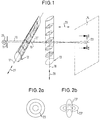
- a narrow parallel imaging light bundle 19 with a circular cross section which, for example, has a starting point, is symbolized by a point light source 11 symbolized as an incandescent lamp 26 with a gap arranged behind it Has a diameter of 0.5 to 1 mm and strikes a cylindrical lens 12 perpendicular to its cylinder axis 17 and parallel to its optical axis 15 which is perpendicular to the cylinder axis 17.
- an imaging surface 14 is provided, on which the two crossed cylindrical lenses 12, 13 together produce a light spot 23 which is a sharp image of the point light source 11.
- the cylindrical lenses 12, 13 change their focal length along the cylinder axes 17, 18, which is illustrated by a curvature of the cylindrical lens surfaces that decreases from one end to the other.
- a desired focal length of the cylindrical lenses 12, 13 can be selected for the imaging light bundle 19, 19 'in such a way that either circular light spots 23 of different sizes according to FIG. 2 a or elliptical light spots 23 ′, 23 ′′ of different sizes according to FIG. 2 b can be realized.
- the focal lengths of the cylindrical lenses 12, 13 must have the same focal length at the points where they are traversed by the imaging light bundle 19, 19 '.
- the elliptical light spots 23 ', 23''with different eccentricities according to FIG. 2b can be achieved in that the imaging light beam 19, 19' traverses locations of more or less different focal lengths of the two cylindrical lenses 12, 13.
- the overall arrangement of the cylindrical lenses 12, 13 or the point light source 11 in the direction of the double arrow 29, i.e. the optical axis 15 can be arranged displaceably in a suitable holder, but the linear displacement of the cylindrical lenses 12, 13 in the direction of the double arrows 27, 28 must remain possible.
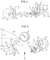
- a laser diode 11 generates the imaging light bundle 19 via a beam expansion optics 22, which strikes the edge region of a cylindrical mirror circular disk 21 at an angle of approximately 20 °, about an axis of rotation perpendicular to the circular plane 20 is rotatable.
- a circular cylindrical mirror 12 ' In the edge area of the circular disk 21 acted upon by the imaging light bundle 19, there is a circular cylindrical mirror 12 'arranged concentrically to the axis of rotation 20 with a circular cylinder axis 17'.
- the radius of curvature of the cylinder mirror 12 changes continuously in the direction of the circumference, namely in Direction of the arrow in the decreasing sense, so that a curvature jump, ie a step, occurs at a circumferential point 16.
- the focal length of the cylinder mirror 12 'increases continuously in the circumferential direction in the direction of the arrow.
- the radii of curvature can change continuously from 300 mm to 1200 mm.
- the imaging light bundle 19 is reflected at a circumferential point of the cylinder mirror 12 'and, as an imaging light bundle 19' which is already optically influenced by the cylinder mirror 12 ', reaches the edge region of a further similar cylindrical mirror circular disk 21, which is also parallel about an axis of rotation 20 is rotatable to the optical axes 15 and is arranged parallel to the first cylinder mirror 12 '.
- the circular cylinder mirror axis 18 'again runs concentrically with the axis of rotation 20 of the cylindrical lens 13'.
- the two cylindrical mirrors 12 ′, 13 ′ are each acted upon by the imaging light bundles 19 and 19 ′ at two points offset by 90 ° to one another.
- the imaging light beam is generated by the cylindrical mirror 13 ' 19 'is reflected as an imaging light bundle 19''to a mirror wheel 24, the axis of rotation 30 of which is perpendicular to the plane defined by the imaging light bundles 19, 19', 19 ''.
- the light bundle 19 '''reflected by the mirror wheel 24 executes a V-shaped scanning movement due to the rotation of the mirror wheel 24 in the direction of the arrow and generates the desired light spot 23 on a concavely curved imaging surface 14.
- suitable rotation of the two cylinder mirrors 12', 13 'Different focal lengths of the cylindrical mirrors 12', 13 ' can be realized about the axes of rotation 20, and different sizes and shapes of the light spot 23 in the sense of FIGS. 2a, 2b can be achieved.
- the cylindrical mirror circular disks 21 according to FIG. 5 are designed such that the channel-like cylindrical mirror 12 'or 13' is located on an end face of the circular disk 21 such that the optical axis 15 at each circumferential point parallel to the axis of rotation 20 or perpendicular to the relevant end face of the circular disk 21, the cylindrical mirror circular disks 21 'can also be designed such that the cylindrical mirror 12', 13 'are on the outer circumference of the cylindrical mirror circular disks 21'.
- the optical axes 15 at each circumferential point represent extensions of the radii of the circular disk 21 'at this point.
- the cylinder mirror axes 17' and 18 ' are again concentric circles to the axis of rotation 20', but are somewhat radially outside the outer circumference of the cylinder mirrors -Circular disk 21 '.
- the axes of rotation 20 'of the cylindrical mirror circular disks 21' must be perpendicular to the axes of rotation 20 of the embodiment shown in solid lines. Otherwise applies here, too, the condition that the positions acted upon by the imaging light bundles 19, 19 'on the circumference of the circular disk 21' are each offset by 90 ° to one another.
- the cylinder mirrors 12 ', 13' can also be arranged on the circumference of a cylindrical mirror circular disk 21 '', as is apparent from FIG. 7.
- the optical axes 15 are at each circumferential point, for example at an angle ⁇ of 45 ° to the axis of rotation 20 ′′. Any other angle ⁇ (see also FIGS. 3, 4) between 0 and 90 ° is also conceivable.
- the embodiment according to FIG. 7 has the advantage that when the cylindrical mirror circular disk 21 '' is produced in an injection mold, the mold half 25 forming the cylindrical mirror 12 'or 13' in the direction of the axis of rotation 20 '' upwards from the circular disk 21 '' without any problems can be lifted off. It is therefore expedient to design the cylindrical mirror circular disk 21 ′′ such that there are no undercuts relative to the axis of rotation 20, so that the circular disk 21 ′′ can be produced in a single injection molding process without burrs.
- the decisive advantage is that the different focal length settings of the two cylindrical lenses 12', 13 'are not only independent of one another, but also by a simple rotary movement around the Axes 20, 20 ', 20' 'can be realized.
- the arrangement of the laser diode 11 and the beam expansion optics 22 can be arranged in the direction of the double arrow 29 'according to FIGS. 3 and 4.
Landscapes
- Physics & Mathematics (AREA)
- General Physics & Mathematics (AREA)
- Optics & Photonics (AREA)
- Mechanical Optical Scanning Systems (AREA)
- Instruments For Viewing The Inside Of Hollow Bodies (AREA)
- Lenses (AREA)
Applications Claiming Priority (2)
| Application Number | Priority Date | Filing Date | Title |
|---|---|---|---|
| DE19612710 | 1996-03-29 | ||
| DE19612710A DE19612710A1 (de) | 1996-03-29 | 1996-03-29 | Lichtfleckerzeugungsvorrichtung |
Publications (2)
| Publication Number | Publication Date |
|---|---|
| EP0798587A2 true EP0798587A2 (fr) | 1997-10-01 |
| EP0798587A3 EP0798587A3 (fr) | 1998-09-02 |
Family
ID=7789969
Family Applications (1)
| Application Number | Title | Priority Date | Filing Date |
|---|---|---|---|
| EP97102321A Withdrawn EP0798587A3 (fr) | 1996-03-29 | 1997-02-13 | Dispositif pour la génération d'un spot lumineux |
Country Status (4)
| Country | Link |
|---|---|
| US (1) | US5844708A (fr) |
| EP (1) | EP0798587A3 (fr) |
| JP (1) | JPH1048553A (fr) |
| DE (1) | DE19612710A1 (fr) |
Cited By (1)
| Publication number | Priority date | Publication date | Assignee | Title |
|---|---|---|---|---|
| EP1452901A1 (fr) * | 2003-02-28 | 2004-09-01 | Samsung Electronics Co., Ltd. | Unité de défilement pour système d'illumination couleur et utilisation dans un système de projection |
Families Citing this family (7)
| Publication number | Priority date | Publication date | Assignee | Title |
|---|---|---|---|---|
| GB9513116D0 (en) * | 1995-06-28 | 1995-08-30 | Sandoz Ltd | Improvements in or relating to organic compounds |
| US6033070A (en) * | 1998-12-16 | 2000-03-07 | Kearns; John P. | Variable focal length lens |
| EP1615067B1 (fr) * | 2003-03-24 | 2015-09-23 | Nikon Corporation | Element optique, systeme optique, dispositif laser, dispositif d'exposition, dispositif de test pour masque et dispositif de traitement de cristaux |
| EP2856239A1 (fr) * | 2012-06-01 | 2015-04-08 | Lemoptix SA | Dispositif de projection |
| US9823351B2 (en) | 2012-12-18 | 2017-11-21 | Uber Technologies, Inc. | Multi-clad fiber based optical apparatus and methods for light detection and ranging sensors |
| US9470520B2 (en) | 2013-03-14 | 2016-10-18 | Apparate International C.V. | LiDAR scanner |
| CA2931055C (fr) | 2013-11-22 | 2022-07-12 | Ottomotto Llc | Etalonnage d'analyseur lidar |
Family Cites Families (11)
| Publication number | Priority date | Publication date | Assignee | Title |
|---|---|---|---|---|
| DE2550815C3 (de) * | 1975-11-12 | 1979-05-31 | Erwin Sick Gmbh Optik-Elektronik, 7808 Waldkirch | Optisches Abtastsystem |
| JPS5735824A (en) * | 1980-08-14 | 1982-02-26 | Ricoh Co Ltd | Light beam scanner |
| JPS596732U (ja) * | 1982-07-06 | 1984-01-17 | 株式会社石田衡器製作所 | 自動計量装置の被計量物排出装置 |
| US4920255A (en) * | 1988-10-31 | 1990-04-24 | Stephen C. Gabeler | Automatic incremental focusing scanner system |
| JPH02175090A (ja) * | 1988-12-27 | 1990-07-06 | Isamu Miyamoto | レーザビーム成形装置 |
| US5054866A (en) * | 1988-12-29 | 1991-10-08 | Ricoh Company, Ltd. | Scanning optical apparatus |
| JP2559898B2 (ja) * | 1990-09-21 | 1996-12-04 | 大日本スクリーン製造株式会社 | 光ビーム走査装置 |
| GB2256937A (en) * | 1991-06-21 | 1992-12-23 | Gec Ferranti Defence Syst | Optical scanner |
| US5343326A (en) * | 1993-08-02 | 1994-08-30 | Xerox Corporation | Compact ros imaging system |
| JP3442845B2 (ja) * | 1994-02-15 | 2003-09-02 | 富士写真フイルム株式会社 | 焦点位置可変光学系及び光ビーム走査装置 |
| US5469290A (en) * | 1994-06-06 | 1995-11-21 | Xerox Corporation | Two-element zoom lens for beam separation error correction |
-
1996
- 1996-03-29 DE DE19612710A patent/DE19612710A1/de not_active Withdrawn
-
1997
- 1997-02-13 EP EP97102321A patent/EP0798587A3/fr not_active Withdrawn
- 1997-03-19 US US08/820,204 patent/US5844708A/en not_active Expired - Fee Related
- 1997-03-28 JP JP9077430A patent/JPH1048553A/ja active Pending
Cited By (2)
| Publication number | Priority date | Publication date | Assignee | Title |
|---|---|---|---|---|
| EP1452901A1 (fr) * | 2003-02-28 | 2004-09-01 | Samsung Electronics Co., Ltd. | Unité de défilement pour système d'illumination couleur et utilisation dans un système de projection |
| US7090359B2 (en) | 2003-02-28 | 2006-08-15 | Samsung Electronics Co., Ltd. | Scrolling unit, color illuminating system, and projection system using the scrolling unit |
Also Published As
| Publication number | Publication date |
|---|---|
| JPH1048553A (ja) | 1998-02-20 |
| US5844708A (en) | 1998-12-01 |
| DE19612710A1 (de) | 1997-10-02 |
| EP0798587A3 (fr) | 1998-09-02 |
Similar Documents
| Publication | Publication Date | Title |
|---|---|---|
| DE69527858T2 (de) | Optische Einrichtung zur Werkstoffbearbeitung mittels Laser | |
| EP2054772B1 (fr) | Installation d'éclairage | |
| DE69619554T2 (de) | Lichtprojektionsvorrichtung | |
| EP0894247B1 (fr) | Dispositif de mesure sans contact de la temperature | |
| EP0185233B1 (fr) | Equipement de guidage d'un rayon laser pour l'usinage de pièces en trois dimensions | |
| DE2431265C2 (de) | Optische Einrichtung zur Erzeugung eines sehr kleinen Strahls | |
| DE3137031C2 (de) | Mehrfachstrahlenbündel-Abtastoptiksystem | |
| DE102014209308A1 (de) | Laserbearbeitungskopf mit Linsenwechselsystem | |
| EP0468328A1 (fr) | Miroir pour changer la forme géométrique d'un faisceau lumineux | |
| DE102019108681A1 (de) | Vorrichtung und Verfahren zur Erzeugung eines Doppel- oder Vielfachspots in der Lasermaterialbearbeitung | |
| WO2010130255A1 (fr) | Dispositif et procédé permettant l'usinage périphérique au laser d'un cordon de matière | |
| DE2925734B2 (de) | Optisches Fehlersuchgerät für Materialbahnen | |
| EP2591875B1 (fr) | Laser doté d'une lentille de transformation du rayonnement | |
| EP0798587A2 (fr) | Dispositif pour la génération d'un spot lumineux | |
| WO2005053896A1 (fr) | Dispositif de traitement d'une surface interne de cylindre a l'aide d'un faisceau laser | |
| DE19846368C1 (de) | Vorrichtung zum Schneiden, Schweißen, Bohren oder Abtragen eines Werkstückes mittels eines Laserstrahles | |
| DE3514302A1 (de) | Optische abtastvorrichtung | |
| EP0458096A1 (fr) | Dispositif annulaire d'illumination à fibre optique | |
| DE102009046809B4 (de) | Belichtungsanlage | |
| EP3418794B1 (fr) | Système modulaire optique pour distributions de la densité de rayonnement proche du foyer à profil de densité de rayonnement alternant | |
| DE202010009009U1 (de) | Vorrichtung zur Lasermaterialbearbeitung mit einem Polygonspiegel | |
| DE69415450T2 (de) | Druckplattenherstellgerät mit Laser | |
| DE69626748T2 (de) | Optischer Scanner | |
| DE102016102430B3 (de) | Langwegzelle | |
| EP0363666A2 (fr) | Appareil optique de balayage |
Legal Events
| Date | Code | Title | Description |
|---|---|---|---|
| PUAI | Public reference made under article 153(3) epc to a published international application that has entered the european phase |
Free format text: ORIGINAL CODE: 0009012 |
|
| AK | Designated contracting states |
Kind code of ref document: A2 Designated state(s): CH DE FR GB IT LI NL |
|
| PUAL | Search report despatched |
Free format text: ORIGINAL CODE: 0009013 |
|
| AK | Designated contracting states |
Kind code of ref document: A3 Designated state(s): CH DE FR GB IT LI NL |
|
| 17P | Request for examination filed |
Effective date: 19990222 |
|
| GRAG | Despatch of communication of intention to grant |
Free format text: ORIGINAL CODE: EPIDOS AGRA |
|
| 17Q | First examination report despatched |
Effective date: 20020515 |
|
| STAA | Information on the status of an ep patent application or granted ep patent |
Free format text: STATUS: THE APPLICATION IS DEEMED TO BE WITHDRAWN |
|
| 18D | Application deemed to be withdrawn |
Effective date: 20020903 |