EP0798611A1 - Mécanisme de rétraction pour système de nettoyage à deux brosses et régulateur variable de dérivé d'inertie pour système de nettoyage rétractable - Google Patents
Mécanisme de rétraction pour système de nettoyage à deux brosses et régulateur variable de dérivé d'inertie pour système de nettoyage rétractable Download PDFInfo
- Publication number
- EP0798611A1 EP0798611A1 EP97301666A EP97301666A EP0798611A1 EP 0798611 A1 EP0798611 A1 EP 0798611A1 EP 97301666 A EP97301666 A EP 97301666A EP 97301666 A EP97301666 A EP 97301666A EP 0798611 A1 EP0798611 A1 EP 0798611A1
- Authority
- EP
- European Patent Office
- Prior art keywords
- link
- cleaning means
- clutch
- brush
- follower
- Prior art date
- Legal status (The legal status is an assumption and is not a legal conclusion. Google has not performed a legal analysis and makes no representation as to the accuracy of the status listed.)
- Granted
Links
- 230000007246 mechanism Effects 0.000 title claims abstract description 16
- 230000009977 dual effect Effects 0.000 title description 9
- 230000033001 locomotion Effects 0.000 claims abstract description 30
- 238000004140 cleaning Methods 0.000 claims description 57
- 238000011144 upstream manufacturing Methods 0.000 claims description 3
- 238000012544 monitoring process Methods 0.000 claims description 2
- 239000002245 particle Substances 0.000 claims description 2
- 108091008695 photoreceptors Proteins 0.000 abstract description 51
- 238000011161 development Methods 0.000 description 10
- 238000003384 imaging method Methods 0.000 description 9
- 238000012546 transfer Methods 0.000 description 8
- 239000000463 material Substances 0.000 description 7
- 230000008901 benefit Effects 0.000 description 5
- 238000011109 contamination Methods 0.000 description 5
- 238000000034 method Methods 0.000 description 5
- 239000003086 colorant Substances 0.000 description 4
- 238000004519 manufacturing process Methods 0.000 description 3
- 238000012986 modification Methods 0.000 description 3
- 230000004048 modification Effects 0.000 description 3
- 239000000843 powder Substances 0.000 description 3
- 230000008569 process Effects 0.000 description 3
- 238000012545 processing Methods 0.000 description 3
- 230000005355 Hall effect Effects 0.000 description 2
- 230000007423 decrease Effects 0.000 description 2
- 230000003247 decreasing effect Effects 0.000 description 2
- 238000005259 measurement Methods 0.000 description 2
- 239000000758 substrate Substances 0.000 description 2
- 230000001133 acceleration Effects 0.000 description 1
- 230000000712 assembly Effects 0.000 description 1
- 238000000429 assembly Methods 0.000 description 1
- 230000008859 change Effects 0.000 description 1
- 230000006835 compression Effects 0.000 description 1
- 238000007906 compression Methods 0.000 description 1
- 230000007547 defect Effects 0.000 description 1
- 238000013461 design Methods 0.000 description 1
- 230000001360 synchronised effect Effects 0.000 description 1
Images




Classifications
-
- G—PHYSICS
- G03—PHOTOGRAPHY; CINEMATOGRAPHY; ANALOGOUS TECHNIQUES USING WAVES OTHER THAN OPTICAL WAVES; ELECTROGRAPHY; HOLOGRAPHY
- G03G—ELECTROGRAPHY; ELECTROPHOTOGRAPHY; MAGNETOGRAPHY
- G03G21/00—Arrangements not provided for by groups G03G13/00 - G03G19/00, e.g. cleaning, elimination of residual charge
- G03G21/0005—Arrangements not provided for by groups G03G13/00 - G03G19/00, e.g. cleaning, elimination of residual charge for removing solid developer or debris from the electrographic recording medium
- G03G21/0035—Arrangements not provided for by groups G03G13/00 - G03G19/00, e.g. cleaning, elimination of residual charge for removing solid developer or debris from the electrographic recording medium using a brush; Details of cleaning brushes, e.g. fibre density
-
- G—PHYSICS
- G03—PHOTOGRAPHY; CINEMATOGRAPHY; ANALOGOUS TECHNIQUES USING WAVES OTHER THAN OPTICAL WAVES; ELECTROGRAPHY; HOLOGRAPHY
- G03G—ELECTROGRAPHY; ELECTROPHOTOGRAPHY; MAGNETOGRAPHY
- G03G21/00—Arrangements not provided for by groups G03G13/00 - G03G19/00, e.g. cleaning, elimination of residual charge
- G03G21/0005—Arrangements not provided for by groups G03G13/00 - G03G19/00, e.g. cleaning, elimination of residual charge for removing solid developer or debris from the electrographic recording medium
Definitions
- This invention relates to an electrostatographic printer or copier, and more particularly to a dual brush retraction mechanism.
- Previous brush retraction mechanisms or systems to accomplish the above-described functions include a system in which solenoids are attached to a mechanism to retract each brush.
- a second brush retraction system is the use of cams to move the brush assemblies about their pivots.
- experimentation showed that using a cam for each brush for retraction and engagement in the brush housings was undesirable because the two cams had to be synchronized to each other in order to maintain the timing required to match each brush motion to the motion of the interdocument zone under the cleaner.
- the size of the cam required would be very large for most applications.
- Other drawbacks to the use of cams include the lack of adjustment in the timing between the two brush motions, and the high accelerations occurring as the cam follower drops off the high portions of the cam lobes which could cause photoreceptor motion quality disturbances.
- a third brush retraction system would be to use a stepper motor drive for each brush assembly rotation about its pivot. This system would allow a large degree of adjustment in the timing of each of the brushes retraction and engagement and repeatable performance. However, the motors required are very large and expensive.
- US-A-4 669 864 discloses an image forming apparatus having a cleaning device arranged on the outer periphery of an image retainer, and bringing into and out of abutment against the image retainer, wherein the cleaning device comprises a first cleaning member and a second cleaning member arranged downstream of the first cleaning member in the moving direction of the surface of the image retainer. A cleaning operation of the second cleaning member against the image retainer is conducted according to a time at which the cleaning operation of the first cleaning member against the image retainer is conducted.
- US-A-5 412 461 discloses an apparatus in which a photoreceptor cleaning blade is mounted to an extension of the coupler link of a four bar linkage.
- a torsion spring is positioned at the pivot of the crank link to create the torque on the crank link.
- a weight or solenoid can also be used to create the torque on the crank link. This torque supplies the force to the mounted cleaning blade.
- the instantaneous confer of rotation is a virtual pivot point which is located on the photoreceptor tangent plane. The linkage reaction forces and the blade friction load all pass through the virtual pivot point leaving the blade load a function of the torque on the crank link. In machines where the cleaning blade is located on a long span of a belt photoreceptor this offers the advantage of blade loading insensitivity to friction without trapping the photoreceptor inside pivot bearings.
- US-A-5 442 422 discloses an apparatus for cleaning an imaging surface with a hybrid cleaner that includes the implementation of a contamination seal in the cleaner unit.
- the contamination seal captures falling accumulated toner from the blade edge and in the brush nip, due to gravitation, which contaminates the xerographic area when the cleaner blade and disturber brush are retracted from the imaging surface.
- the contamination seal rests along the length of the blade portion that extends from the blade holder. In this position, the contamination seal does not touch the imaging surface to cause scratches nor does it interfere with the blade's ability to clean the imaging surface. Implementation of the contamination seal contains toner emission within the cleaner from the blade edge and brush nip.
- US-A-5 450 186 discloses a flexible cleaner brush belt that increases the brush belt life by flexing away from the photoreceptor when not in use.
- the flexible belt is lifted away from contact with the photoreceptor and placed back into contact with the photoreceptor by a camming device.
- a camming device attached to linkages increases the diameter of the flexible brush belt to lift the brush belt away from contact with the imaging surface.
- the camming device urges the belt brush back into contact with the imaging surface by decreasing the diameter of the brush belt. This movement of the brush belt increases the brush belt life and does not cause print quality defects, excessive toner clouding, or loss of machine productivity.
- an apparatus for cleaning particles from a movable surface of a multipass image on image printing machine comprising: at least two means for cleaning the surface including a first cleaning means and a second cleaning means, the first cleaning means being located upstream from the second cleaning means in a direction of motion of the surface; and a mechanism for pivotally supporting the first cleaning means and said second cleaning means, having an actual pivot point on an axis parallel to and above the surface and perpendicular to the direction of motion of the surface, the mechanism enabling the first cleaning means and the second cleaning means to sequentially retract from and engage with the surface.
- a reproduction machine utilizes a charge retentive member in the form of the photoconductive or photoreceptive belt 10 consisting of a photoconductive or photoreceptor surface 11 and an electrically conductive, light transmissive substrate mounted for movement pass charging station A, and exposure station B, developer stations C, transfer station D, fusing station E and cleaning station F.
- Belt 10 moves in the direction of arrow 16 to advance successive portions thereof sequentially through the various processing stations disposed about the path of movement thereof.
- Belt 10 is entrained about a plurality of rollers 18, 20 and 22, the former of which can be used to provide suitable tensioning of the photoreceptor belt 10.
- Motor 23 rotates roller 18 to advance belt 10 in the direction of arrow 16.
- Roller 20 is coupled to motor 23 by suitable means such as a belt drive (not shown).
- a corona device such as a scorotron, corotron or dicorotron indicated generally by the reference numeral 24, charges the belt 10 to a selectively high uniform positive or negative potential. Any suitable control, well known in the art, may be employed for controlling the corona device 24.
- the charged portions of the photoreceptor surface are advanced through exposure station B.
- the uniformly charged photoreceptor or charge retentive surface 10 is exposed to a laser based input andlor output scanning device 25 which causes the charge retentive surface to be discharged in accordance with the output from the scanning device (for example a two level Raster Output Scanner (ROS)).
- ROS Raster Output Scanner
- the photoreceptor which is initially charged to a voltage, undergoes dark decay to a voltage level. When exposed at the exposure station B it is discharged to near zero or ground. potential for the image area in all colors.
- a development system advances development materials into contact with the electrostatic latent images.
- the development system 30 comprises first 42, second 40, third 34 and fourth 32 developer apparatuses. (However, this number may increase or decrease depending upon the number of colors, i.e. here four colors are referred to, thus, there are four developer housings.)
- the first developer apparatus 42 comprises a housing containing a donor roll 47, a magnetic roller 48, and developer material 46.
- the second developer apparatus 40 comprises a housing containing a donor roll 43, a magnetic roller 44, and developer material 45.
- the third developer apparatus 34 comprises a housing containing a donor roll 37, a magnetic roller 38, and developer material 39.
- the fourth developer apparatus 32 comprises a housing containing a donor roll 35, a magnetic roller 36, and developer material 33.
- the magnetic rollers 36, 38, 44, and 48 develop toner onto donor rolls 35, 37, 43 and 47 respectively.
- the donor rolls 35, 37, 43, and 47 then develop the toner onto the imaging or photoreceptor surface 11.
- development housings 32, 34, 40, 42, and any subsequent development housings must be scavengeless so as not to disturb the image formed by the previous development apparatus. All four housings contain developer material 33, 39, 45, 46 of selected colors. Electrical biasing is accomplished via power supply 41, electrically connected to developer apparatuses 32, 34, 40 and 42.
- Sheets of substrate or support material 58 are advanced to transfer station D from a supply tray, not shown. Sheets are fed from the tray by a sheet feeder, also not shown, and advanced to transfer station D through a corona charging device 60. After transfer, the sheet continues to move in the direction of arrow 62, to fusing station E.
- Fusing station E includes a fuser assembly, indicated generally by the reference numeral 64, which permanently affixes the transferred toner powder images to the sheets.
- fuser assembly 64 includes a heated fuser roller 66 adapted to be pressure engaged with a back-up roller 68 with the toner powder images contacting fuser roller 66. In this manner, the toner powder image is permanently affixed to the sheet.
- copy sheets are directed to a catch tray, not shown, or a finishing station for binding, stapling, collating, etc., and removal from the machine by the operator.
- the sheet may be advanced to a duplex tray (not shown) from which it will be retumed to the processor for receiving a second side copy.
- a lead edge to trail edge reversal and an odd number of sheet inversions is generally required for presentation of the second side for copying.
- overlay information in the form of additional or second color information is desirable on the first side of the sheet, no lead edge to trail edge reversal is required.
- the return of the sheets for duplex or overlay copying may also be accomplished manually.
- Residual toner and debris remaining on photoreceptor belt 10 after each copy is made, may be removed at cleaning station F wlth a brush or other type of cleaning system 70.
- the cleaning system is supported under the photoreceptive belt by two backers 160 and 170.
- a negatively biased pre-clean 161 is located upstream from the cleaning system in the direction of motion of the photoreceptor belt 10.
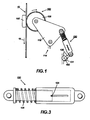
- a six bar linkage is used to retract and engage the cleaner brushes.
- Frame link 190 is shown in Figure 4.
- Rocker link 115 is an endplate with a pivot point 114.
- Crank link 130 is mounted symmetrically between two brushes 100, 102 (see Figure 4) and on the opposite side of the cleaner endplate from the photoreceptor belt 10.
- a coupler link 120 connects the crank link 130 to the rocker link 115. As the crank rotates (see arrow 131), the coupler 120 transmits motion to the follower 115 (e.g. rocker) causing it to move toward and away from the photoreceptor belt 10.
- FIGs 2a and 2b show respective frontal and side views of an interference wheel that enables interference between a brush and a photoreceptor belt 10 to occur with little tolerance variation.
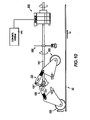
- the crank motion, of the present invention is controlled by a clutch 200 (see Figure 10) which engages and disengages causing the retraction crank shaft 180 to rotate.
- the engaged clutch 200 allows the retraction crank shaft 180 to rotate 180° to retract the cleaner brush and then is disengaged, causing the retraction crank shaft 180 to stop rotating.
- the internal resistance drag of the cleaner due to seals, brush compression etc. causes the brush motion to stop. Due to the large tolerance (i.e.
- brush shaft 175 carries an interference wheel 105 which contacts the photoreceptor backer 160 outside of the photoreceptor belt path and prevents the brush 100 from being over compressed.
- FIG. 3 shows a schematic view of a compressible coupler link in the present invention.
- the four bar linkage (see Figure 1) enables the motion required for nominal brush interference to be exceeded. Since the interference wheels will stop the brushes when they contact the backer bars the coupler link must be made compressible.
- the coupler link 120 consists of two telescoping portions which are spring loaded. When the brush is not contacting the photoreceptor belt 10, spring 125 maintains the coupler link 120 in an extended position. A pin 126 prevents rotation of the two coupler link 120 halves and limits extension of the coupler link.
- FIG. 4 shows a schematic view of the six bar linkage, of the present invention, for retraction of a dual brush cleaner.
- a second brush 102 must also be retracted and engaged to the photoreceptor belt 10.
- the second brush 102 In order that the retraction and engagement of the second brush always occurs in the interdocument zones (i.e. the area between the imaging regions on the imaging surface) of the photoreceptor belt 10, the second brush 102 always lags the engagement or retraction motion of the first brush 100 by the time it takes the interdocument zone to move the distance between the two brushes 100, 102.
- the second brush 102 which carries an interference wheel 106, is also moved by a four bar linkage but, rather than being driven directly by the crank link 130, the second brush is driven by an extension 120' of the coupler link 120 for the first brush four bar linkage.
- a connection point 119 to the first brush coupler link 120 is chosen such that the motion of the second brush 102 lags behind that of the first brush 100, in the direction of motion of the photoreceptor belt 10 shown by arrow 16.
- a six bar linkage (rather then an eight bar linkage) is used for a dual brush cleaner because the four bar linkage of the second brush 102 (located downstream from the first brush in the direction of motion of the photoreceptor belt 10 shown by arrow 16) four bar linkage has the frame link 190 in common with the first brush four bar linkage and uses the first brush coupler link 120 to drive the second brush 102, only two additional links 121 (i.e. coupler link) and 116 (i.e. rocker or follower link) are required for a dual brush cleaner retraction system.
- Link 121 is similar to link 120 and includes a spring 127.
- the rocker link 116 has a pivot point 110. Hence, the entire two brush retraction system includes a six bar linkage.
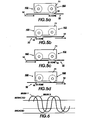
- FIGS 5a-5d show, sequentially, the four position actuation timing of a cleaning unit 71 in accordance with the present invention.
- the lag in retraction and engagement of the two brushes built into the six bar linkage does not allow any variation in lag timing or variation in lag timing versus retraction timing.
- These timing factors must be designed into the six bar linkage.
- the distance between the brushes on some cleaner and the speed and size of the interdocument zones were such that the design of a six bar linkage which would satisfy all of these requirements did not fit into the architecture of the printing machine.
- a clutch or stepper motor or like device
- This clutch has an intermediate stopping point between the 180° stops for each retraction and engagement cycle of the brushes.
- both brushes 100, 102 are in the "home position" (i.e. both brushes 100, 102 are retracted from the photoreceptor belt 10).
- the operation for engagement is to actuate the clutch 200 to a first position, causing the first brush 100 to engage the photoreceptor belt 10 in interdocument zone 14 and the second brush 102 to move part of the way towards the photoreceptor belt 10 but not contact it - see Figure 5b.
- the second clutch actuation waits for the interdocument zone 14 to move toward the second brush 102.
- the second brush 102 moves the remainder of the distance to contact the photoreceptor belt 10 in the interdocument zone 14 and the first brush linkage 115 (see Figure 1) over extends, compressing the coupler link 120.
- the clutch 200 is in the second position and has rotated 180° from the start position and both brushes 100, 102 are engaged with the photoreceptor belt 10 - see Figure 5c.
- the clutch 200 is actuated to a third position. This retracts the first brush 100 partially away from the photoreceptor belt 10 and leaves the second brush 102 in contact with the photoreceptor belt 10.
- the retraction cycle then pauses to wait for the interdocument zone 14 to move to the second brush 102 - see Figure 5d.
- the clutch 200 then actuates to the fourth position which completely retracts the first brush 100 and the second brush 102, returning to the original home position - see Figure 5a.
- the six bar linkage retraction system enables the two brushes of the dual electrostatic retractable brush cleaner to disengage from the photoreceptor, independently, at the arrival of the interdocument zone ahead of the developed color multipass (untransferred) image. After transfer, the six bar linkage retraction system enables the two brushes to engage the photoreceptor, independently, at the arrival of the interdocument zone, ahead of the untransferred image.
- the brushes are linked to a single retraction crank shaft 180.
- the rotation of the retraction crank shaft 180 is controlled by a clutch 200 (also referred to as a retraction clutch).
- FIG 7 shows an isometric view of the four-position self-indexing clutch 200 to control the retraction/engagement of the dual brush cleaner.
- the clutch 200 has four magnetic poles 205, 210, 215, 220 spaced equally around its index wheel 230. Three of the poles are magnetic south 205, 210, 215 and the fourth pole is magnetic north 220.
- the four position clutch 200 can sense its position through the use of a device such as the Hall effect sensor and four magnets. The home position is sensed with a north pole and the other positions are sensed using south poles. This allows the mechanism to always be capable of returning to a known home position to reset the retraction and engagement process.
- a sensor 240 on top of the clutch 200 will detect a north pole or a south pole when it passes by, the sensor 240 being connected to a control system 290.
- the north pole 220 corresponds to the cleaner state or position where the first brush and the second brush are retracted (see Figure 5a).
- the south poles 205, 210, 215 correspond to the other three states (see Figures 5b-5d).
- the clutch sensor 240 detects a pole, the clutch 200 is disabled by control system 290.
- a problem arises in that there is a finite amount of processing time to disable the clutch 200, because the cleaner has mechanical drift and continues to move for some time after the clutch 200 is disabled. This drift can vary from pole to pole as the inertia of the linkage is different throughout the cycle, and also change due to variations in frictional force with time and wear.
- Still another solution is to add a brake to the retraction drive shaft to reduce the drift of the cleaner, thereby making the brake strong enough to reduce the drift of the cleaner over the life of the cleaner.
- torque requirements increased cleaner UMC (i.e. unit manufacturing costs), decreased reliability, and increased drive cost to the cleaner are added.
- the preferred embodiment involves modifying the retraction clutch and using an encoder wheel to monitor the mechanical drift of each cleaner state.
- the main modifications to the retraction clutch are two fold. First, the self-indexing feature of the clutch (described above) is disconnected, and the magnetic pole sensor outputs are made available to the control system 290 (see Figure 10) enabling the control system 290 to decide when the clutch 200 is engaged and disengaged. Second, the equally spaced poles on the index wheel 230 are rotated with respect to the keyed retraction crank 180 so that the magnetic poles can be detected by the sensor 240 before the cleaner reaches the desired cleaner state. At a clutch input speed of 240rpm, a pole is seen every 90°, or every 62.5ms.
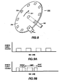
- FIG 8 shows a schematic of an encoder 250.
- the encoder wheel 236 is attached to the retraction crank shaft 180 on the output side of the retraction clutch 200.
- the encoder 250 provides output pulses as shown in Figure 9A.
- the circumference of the encoder wheel 236 would contain 360 divisions with each pulse corresponding to one degree of rotation.
- the control system 290 starts monitoring the encoder 250 output as it rotates in the direction of arrow 231.
- the cleaner has stopped moving. This length of time is the "drift" as shown in Figure 9B.
- the control system 290 detects the north pole 31.25ms before the desired state and waits 21.25ms (i.e. 31.25ms - 10ms) before disabling the clutch 200. 10ms of "drift" later, the cleaner should be in the desired state (i.e. in this case, the home position). At the same time, the drift is being measured to verify that it is indeed 10ms. If the drift increases or decreases, the control system 290 can adjust accordingly on the next cycle.
- This invention known as a variable inertia drift controller, has the advantage of wider manufacturing tolerances and higher reliability over the life of the cleaner.
- variable inertia drift controller is the use of an irregularly spaced encoder wheel to act as the retraction home position sensor.
- a wide pulse would indicate the presence of the home position, and a 360 division encoder would enable the control system 290 to count 90 pulses (or 90°) until the next cleaner state.
- the encoder pulses would still be used to compensate for changing drift as described above.
- the processor could perform these drift measurements every 2000 prints, for example, in a special "print quality" cycle, reducing the need for extra computing power or cost while providing the additional advantage of eliminating the need for a magnetic indexing wheel on the clutch, thus, reducing the UMC.
- Figure 10 shows a schematic of an embodiment of the present invention using a six bar linkage retraction system with an encoder and a four-position clutch with a sensor.
- Figure 10 shows a complete brush retraction assembly.
- the present invention utilizes a six bar linkage cleaner brush retraction system.
- the six bar linkage cleaner brush retraction system, of the present invention is an important feature of the cleaner subsystem in printers and copiers.
- This mechanism enables brush retraction (and engagement with the photoreceptor) while providing good control over the brush interference and the capability of changing retraction and engagement timing parameters through clutch actuation times in software and clutch shaft speed.
- the mechanism is relatively inexpensive and provides retraction and engagement with relatively soft contacts to the photoreceptor to minimize impacts to photoreceptor motion quality.
- Another advantage of this invention is that it is adaptable to printers or copiers with tight space constraints preclude the use of larger traditional solenoids and cams.
- a four position clutch is used to provide magnetic pole sensor outputs to the system controller to decide when the clutch, which drives the six bar linkage, is engaged and disengaged.
- the index wheel of the clutch has four equally spaced magnets that are located relative to the retraction crank shaft so that there is a significant amount of time between detecting a pole and the corresponding desired state. This "significant" amount of time allows the processor to vary its clutch disable time in order to compensate for mechanical drift.
- An encoder is used to monitor the actual mechanical drift of each cleaner state. The measured drift is fed back to the controller which can compensate for changes in drift on the next cycle.
Landscapes
- Physics & Mathematics (AREA)
- General Physics & Mathematics (AREA)
- Cleaning In Electrography (AREA)
- Hydraulic Clutches, Magnetic Clutches, Fluid Clutches, And Fluid Joints (AREA)
- Accessory Devices And Overall Control Thereof (AREA)
- Brushes (AREA)
- Arrangement And Mounting Of Devices That Control Transmission Of Motive Force (AREA)
- Mechanical Operated Clutches (AREA)
Applications Claiming Priority (2)
| Application Number | Priority Date | Filing Date | Title |
|---|---|---|---|
| US08/624,160 US5669055A (en) | 1996-03-29 | 1996-03-29 | Dual brush cleaner retraction mechanism and variable inertia drift controller for retractable cleaner |
| US624160 | 1996-03-29 |
Publications (2)
| Publication Number | Publication Date |
|---|---|
| EP0798611A1 true EP0798611A1 (fr) | 1997-10-01 |
| EP0798611B1 EP0798611B1 (fr) | 2002-09-25 |
Family
ID=24500899
Family Applications (1)
| Application Number | Title | Priority Date | Filing Date |
|---|---|---|---|
| EP97301666A Expired - Lifetime EP0798611B1 (fr) | 1996-03-29 | 1997-03-12 | Mécanisme de rétraction pour système de nettoyage à deux brosses et régulateur variable de dérive d'inertie pour système de nettoyage rétractable |
Country Status (7)
| Country | Link |
|---|---|
| US (1) | US5669055A (fr) |
| EP (1) | EP0798611B1 (fr) |
| JP (1) | JPH1010948A (fr) |
| BR (1) | BR9701480A (fr) |
| CA (1) | CA2192129C (fr) |
| DE (1) | DE69715709T2 (fr) |
| ES (1) | ES2184030T3 (fr) |
Families Citing this family (11)
| Publication number | Priority date | Publication date | Assignee | Title |
|---|---|---|---|---|
| US5930575A (en) * | 1997-09-22 | 1999-07-27 | Xerox Corporation | Apparatus and method for reduced photoreceptor impact by a retractable cleaner |
| US6035175A (en) * | 1998-07-01 | 2000-03-07 | Xerox Corporation | Single revolution clutch with auto-homing feature |
| JP2000275983A (ja) * | 1999-03-24 | 2000-10-06 | Toshiba Tec Corp | 転写装置、及びこの転写装置を備えた画像形成装置 |
| US6430387B1 (en) * | 2000-12-20 | 2002-08-06 | Xerox Corporation | Electrostatographic reproduction machine having a motion-defect-free cleaning method and assembly |
| DE102004016668A1 (de) * | 2004-04-05 | 2005-10-20 | Peter Kuelzer | Teleskopeinrichtung, insbesondere Trekking- oder Wanderstock |
| US7428395B2 (en) * | 2005-03-21 | 2008-09-23 | Kabushiki Kaisha Toshiba | Image forming apparatus equipped with developing unit to make developing and simultaneous cleaning and image forming method |
| US7251448B2 (en) * | 2005-08-31 | 2007-07-31 | Xerox Corporation | Cleaning blade control apparatus and method |
| EP2601416B1 (fr) | 2011-06-27 | 2015-04-15 | Ludwig Ehrhardt GmbH | Système de fluide sous pression, en particulier système hydraulique |
| DE102011105584B4 (de) * | 2011-06-27 | 2016-02-18 | Ludwig Ehrhardt Gmbh | Druckmittelsystem, insbesondere Hydrauliksystem |
| JP5602112B2 (ja) * | 2011-08-26 | 2014-10-08 | シャープ株式会社 | 画像形成装置 |
| JP6103206B2 (ja) | 2013-03-25 | 2017-03-29 | セイコーエプソン株式会社 | 記録装置 |
Citations (5)
| Publication number | Priority date | Publication date | Assignee | Title |
|---|---|---|---|---|
| JPS57203270A (en) * | 1981-06-08 | 1982-12-13 | Ricoh Co Ltd | Cleaning device for recording medium |
| JPS5814176A (ja) * | 1981-07-17 | 1983-01-26 | Ricoh Co Ltd | 記録媒体クリ−ニング装置 |
| US5412461A (en) * | 1994-05-05 | 1995-05-02 | Xerox Corporation | Friction load insensitive mounting for blade |
| JPH07230237A (ja) * | 1994-02-20 | 1995-08-29 | Mita Ind Co Ltd | 画像形成装置のクリーニング装置 |
| US5493383A (en) * | 1994-11-18 | 1996-02-20 | Xerox Corporation | Sequenced cleaner retraction method and apparatus |
Family Cites Families (8)
| Publication number | Priority date | Publication date | Assignee | Title |
|---|---|---|---|---|
| JPS57192562U (fr) * | 1981-05-30 | 1982-12-06 | ||
| US4519699A (en) * | 1983-11-16 | 1985-05-28 | Ricoh Company, Ltd. | Electrophotographic copying apparatus including toner cleaning arrangement |
| US4669864A (en) * | 1985-01-31 | 1987-06-02 | Konishiroku Photo Industry Co., Ltd. | Image forming apparatus |
| US5083169A (en) * | 1988-04-06 | 1992-01-21 | Ricoh Company, Ltd. | Device for removing deposits from a photoconductive element of an image recorder which is movable between a cleaning and non-cleaning position |
| JP2741879B2 (ja) * | 1988-12-20 | 1998-04-22 | 株式会社リコー | 電子写真装置のクリーニング装置 |
| JPH04261573A (ja) * | 1991-02-16 | 1992-09-17 | Hitachi Koki Co Ltd | 乾式電子写真装置 |
| US5442422A (en) * | 1994-06-08 | 1995-08-15 | Xerox Corporation | Toner contamination seal device for cleaner |
| US5450186A (en) * | 1994-06-17 | 1995-09-12 | Lundy; Douglas A. | Retractable flexible cleaner brush |
-
1996
- 1996-03-29 US US08/624,160 patent/US5669055A/en not_active Expired - Fee Related
- 1996-12-05 CA CA002192129A patent/CA2192129C/fr not_active Expired - Fee Related
-
1997
- 1997-03-12 ES ES97301666T patent/ES2184030T3/es not_active Expired - Lifetime
- 1997-03-12 DE DE69715709T patent/DE69715709T2/de not_active Expired - Fee Related
- 1997-03-12 EP EP97301666A patent/EP0798611B1/fr not_active Expired - Lifetime
- 1997-03-24 JP JP9069963A patent/JPH1010948A/ja not_active Abandoned
- 1997-03-25 BR BR9701480A patent/BR9701480A/pt not_active IP Right Cessation
Patent Citations (5)
| Publication number | Priority date | Publication date | Assignee | Title |
|---|---|---|---|---|
| JPS57203270A (en) * | 1981-06-08 | 1982-12-13 | Ricoh Co Ltd | Cleaning device for recording medium |
| JPS5814176A (ja) * | 1981-07-17 | 1983-01-26 | Ricoh Co Ltd | 記録媒体クリ−ニング装置 |
| JPH07230237A (ja) * | 1994-02-20 | 1995-08-29 | Mita Ind Co Ltd | 画像形成装置のクリーニング装置 |
| US5412461A (en) * | 1994-05-05 | 1995-05-02 | Xerox Corporation | Friction load insensitive mounting for blade |
| US5493383A (en) * | 1994-11-18 | 1996-02-20 | Xerox Corporation | Sequenced cleaner retraction method and apparatus |
Non-Patent Citations (3)
| Title |
|---|
| PATENT ABSTRACTS OF JAPAN vol. 007, no. 057 (P - 181) 9 March 1983 (1983-03-09) * |
| PATENT ABSTRACTS OF JAPAN vol. 007, no. 087 (P - 190) 9 April 1983 (1983-04-09) * |
| PATENT ABSTRACTS OF JAPAN vol. 095, no. 011 26 December 1995 (1995-12-26) * |
Also Published As
| Publication number | Publication date |
|---|---|
| EP0798611B1 (fr) | 2002-09-25 |
| US5669055A (en) | 1997-09-16 |
| CA2192129A1 (fr) | 1997-09-30 |
| ES2184030T3 (es) | 2003-04-01 |
| MX9700977A (es) | 1997-09-30 |
| DE69715709T2 (de) | 2003-02-13 |
| BR9701480A (pt) | 1998-06-30 |
| JPH1010948A (ja) | 1998-01-16 |
| DE69715709D1 (de) | 2002-10-31 |
| CA2192129C (fr) | 2001-04-10 |
Similar Documents
| Publication | Publication Date | Title |
|---|---|---|
| JP4977499B2 (ja) | 画像形成装置 | |
| EP0798611B1 (fr) | Mécanisme de rétraction pour système de nettoyage à deux brosses et régulateur variable de dérive d'inertie pour système de nettoyage rétractable | |
| US8494433B2 (en) | Recording-medium positioning device and image forming apparatus employing the device | |
| EP0713160B1 (fr) | Appareil de nettoyage de la surface d'une bande mobile | |
| EP0592197B1 (fr) | Dispositif de transfert d'images | |
| US11934116B2 (en) | Transfer unit with a non-selected transfer roller retracted behind a guide and image forming apparatus therewith | |
| US11714367B2 (en) | Transfer unit and image forming apparatus therewith | |
| US11119423B2 (en) | Photosensitive member unit and image forming apparatus | |
| US4921236A (en) | Recycling automatic document feeder | |
| US11520255B2 (en) | Transfer unit capable of switching a transfer roller to one of a size appropriate to a recording medium | |
| CA2124504C (fr) | Brosse anti-trainage | |
| US5493383A (en) | Sequenced cleaner retraction method and apparatus | |
| US5006903A (en) | Sheet separating device and apparatus for use therein | |
| US8398078B2 (en) | Post-processing device and image forming apparatus including the same | |
| US6024497A (en) | Bushing with molded spring | |
| CN110439938B (zh) | 单向离合器和片材传送装置 | |
| US5282010A (en) | Stripping of paper from photoreceptor belts with reduced stress | |
| JP4293420B2 (ja) | ベルト移動装置及び画像形成装置 | |
| US8014697B2 (en) | Cleaning device, and image forming apparatus provided with the same | |
| EP0810494B1 (fr) | Procédé de détermination d'erreurs de temps de rétraction d'un dispositif de nettoyage | |
| EP0903647B1 (fr) | Barre de pression incliné et matière absorbant les chocs pour une pression réduite de photorécepteur dans un dispositif de nettoyage escamotable | |
| MXPA97000977A (en) | Retraction mechanism of a double brush cleaner and inertiavalable displacement controller for the retrai cleaner | |
| EP0577490A1 (fr) | Appareil de formation d'images muni d'un mécanisme pour séparer l'élément de support d'image de l'élément de support de transfert | |
| US12566393B2 (en) | Transfer unit and image forming apparatus therewith | |
| US6035175A (en) | Single revolution clutch with auto-homing feature |
Legal Events
| Date | Code | Title | Description |
|---|---|---|---|
| PUAI | Public reference made under article 153(3) epc to a published international application that has entered the european phase |
Free format text: ORIGINAL CODE: 0009012 |
|
| AK | Designated contracting states |
Kind code of ref document: A1 Designated state(s): DE ES FR GB IT |
|
| 17P | Request for examination filed |
Effective date: 19980401 |
|
| GRAG | Despatch of communication of intention to grant |
Free format text: ORIGINAL CODE: EPIDOS AGRA |
|
| 17Q | First examination report despatched |
Effective date: 20011016 |
|
| GRAG | Despatch of communication of intention to grant |
Free format text: ORIGINAL CODE: EPIDOS AGRA |
|
| GRAH | Despatch of communication of intention to grant a patent |
Free format text: ORIGINAL CODE: EPIDOS IGRA |
|
| GRAH | Despatch of communication of intention to grant a patent |
Free format text: ORIGINAL CODE: EPIDOS IGRA |
|
| GRAA | (expected) grant |
Free format text: ORIGINAL CODE: 0009210 |
|
| AK | Designated contracting states |
Kind code of ref document: B1 Designated state(s): DE ES FR GB IT |
|
| REG | Reference to a national code |
Ref country code: GB Ref legal event code: FG4D |
|
| REF | Corresponds to: |
Ref document number: 69715709 Country of ref document: DE Date of ref document: 20021031 |
|
| ET | Fr: translation filed | ||
| REG | Reference to a national code |
Ref country code: ES Ref legal event code: FG2A Ref document number: 2184030 Country of ref document: ES Kind code of ref document: T3 |
|
| PLBE | No opposition filed within time limit |
Free format text: ORIGINAL CODE: 0009261 |
|
| STAA | Information on the status of an ep patent application or granted ep patent |
Free format text: STATUS: NO OPPOSITION FILED WITHIN TIME LIMIT |
|
| 26N | No opposition filed |
Effective date: 20030626 |
|
| PGFP | Annual fee paid to national office [announced via postgrant information from national office to epo] |
Ref country code: FR Payment date: 20040309 Year of fee payment: 8 |
|
| PGFP | Annual fee paid to national office [announced via postgrant information from national office to epo] |
Ref country code: GB Payment date: 20040310 Year of fee payment: 8 |
|
| PGFP | Annual fee paid to national office [announced via postgrant information from national office to epo] |
Ref country code: ES Payment date: 20040318 Year of fee payment: 8 |
|
| PGFP | Annual fee paid to national office [announced via postgrant information from national office to epo] |
Ref country code: DE Payment date: 20040325 Year of fee payment: 8 |
|
| PG25 | Lapsed in a contracting state [announced via postgrant information from national office to epo] |
Ref country code: IT Free format text: LAPSE BECAUSE OF NON-PAYMENT OF DUE FEES Effective date: 20050312 Ref country code: GB Free format text: LAPSE BECAUSE OF NON-PAYMENT OF DUE FEES Effective date: 20050312 |
|
| PG25 | Lapsed in a contracting state [announced via postgrant information from national office to epo] |
Ref country code: ES Free format text: LAPSE BECAUSE OF NON-PAYMENT OF DUE FEES Effective date: 20050314 |
|
| PG25 | Lapsed in a contracting state [announced via postgrant information from national office to epo] |
Ref country code: DE Free format text: LAPSE BECAUSE OF NON-PAYMENT OF DUE FEES Effective date: 20051001 |
|
| GBPC | Gb: european patent ceased through non-payment of renewal fee |
Effective date: 20050312 |
|
| PG25 | Lapsed in a contracting state [announced via postgrant information from national office to epo] |
Ref country code: FR Free format text: LAPSE BECAUSE OF NON-PAYMENT OF DUE FEES Effective date: 20051130 |
|
| REG | Reference to a national code |
Ref country code: FR Ref legal event code: ST Effective date: 20051130 |
|
| REG | Reference to a national code |
Ref country code: ES Ref legal event code: FD2A Effective date: 20050314 |