EP0799098B1 - Verfahren zum erzeugen von stehenden schallwellen,beschallungsverfahren mit einer stehenden schallwelle,und eine stehende schallwelle verwendende beschaller - Google Patents
Verfahren zum erzeugen von stehenden schallwellen,beschallungsverfahren mit einer stehenden schallwelle,und eine stehende schallwelle verwendende beschaller Download PDFInfo
- Publication number
- EP0799098B1 EP0799098B1 EP95943966A EP95943966A EP0799098B1 EP 0799098 B1 EP0799098 B1 EP 0799098B1 EP 95943966 A EP95943966 A EP 95943966A EP 95943966 A EP95943966 A EP 95943966A EP 0799098 B1 EP0799098 B1 EP 0799098B1
- Authority
- EP
- European Patent Office
- Prior art keywords
- wave
- vibratable member
- sonic wave
- vibrating element
- standing sonic
- Prior art date
- Legal status (The legal status is an assumption and is not a legal conclusion. Google has not performed a legal analysis and makes no representation as to the accuracy of the status listed.)
- Expired - Lifetime
Links
Images


Classifications
-
- B—PERFORMING OPERATIONS; TRANSPORTING
- B06—GENERATING OR TRANSMITTING MECHANICAL VIBRATIONS IN GENERAL
- B06B—METHODS OR APPARATUS FOR GENERATING OR TRANSMITTING MECHANICAL VIBRATIONS OF INFRASONIC, SONIC, OR ULTRASONIC FREQUENCY, e.g. FOR PERFORMING MECHANICAL WORK IN GENERAL
- B06B3/00—Methods or apparatus specially adapted for transmitting mechanical vibrations of infrasonic, sonic, or ultrasonic frequency
-
- B—PERFORMING OPERATIONS; TRANSPORTING
- B01—PHYSICAL OR CHEMICAL PROCESSES OR APPARATUS IN GENERAL
- B01F—MIXING, e.g. DISSOLVING, EMULSIFYING OR DISPERSING
- B01F31/00—Mixers with shaking, oscillating, or vibrating mechanisms
- B01F31/80—Mixing by means of high-frequency vibrations above one kHz, e.g. ultrasonic vibrations
- B01F31/86—Mixing by means of high-frequency vibrations above one kHz, e.g. ultrasonic vibrations with vibration of the receptacle or part of it
-
- C—CHEMISTRY; METALLURGY
- C12—BIOCHEMISTRY; BEER; SPIRITS; WINE; VINEGAR; MICROBIOLOGY; ENZYMOLOGY; MUTATION OR GENETIC ENGINEERING
- C12N—MICROORGANISMS OR ENZYMES; COMPOSITIONS THEREOF; PROPAGATING, PRESERVING, OR MAINTAINING MICROORGANISMS; MUTATION OR GENETIC ENGINEERING; CULTURE MEDIA
- C12N1/00—Microorganisms; Compositions thereof; Processes of propagating, maintaining or preserving microorganisms or compositions thereof; Processes of preparing or isolating a composition containing a microorganism; Culture media therefor
- C12N1/06—Lysis of microorganisms
- C12N1/066—Lysis of microorganisms by physical processes
Definitions
- the present invention relates to sonic waves and in particular relates to generating ultrasonic waves which can be used to sonicate particulate material.
- Ultrasonic energy is used in a variety of industrial and scientific areas to disrupt or otherwise break apart particulate material ranging from sewage to microorganisms such as viruses or bacteria.
- the manner in which ultrasonic energy or ultrasound disrupts solid materials has been described as the propagation of an ultrasonic sound wave in a medium which causes pressure changes within the medium. These pressure changes can be as great as 20,000 atmospheres and particulate material in the medium that is unable to withstand the pressure changes is disrupted.
- Sonicators are devices which are used to disrupt particulate material using ultrasonic waves. Sonicators generally can be categorized into three categories. First, “immersion” sonicators typically involve dipping a vibrating probe which emits ultrasonic waves into a liquid sample. U.S. Patent No. 5,074,474 describes an immersion type sonicator.
- bath sonicators generally comprise a container that vibrates and any liquid in the container is subject to ultra-sonic waves produced by the vibrating container.
- the container is filled with water and a sample contained in a second container is placed in the water. Accordingly, any solids in the sample container are subjected to ultrasonic energy.
- a bath type sonicator is disclosed in U.S. Patent No. 4,8974,137.
- direct sonicators apply ultrasonic energy directly to a vessel containing a sample. If present, particulate material present in the sample is subjected to ultrasonic energy.
- a direct sonicator is disclosed in U.S. Patent No. 4,983,523.
- EP-A-0 337 690 describes a method and an apparatus for preparing sample nucleic acids for hybridization.
- the known apparatus includes an ultrasonic transducer operatively coupled to a sample cuvette, as set forth in the precharacterizing portion of claim 1.
- WO-A-92 12807 teaches a device for causing a filtering screen, a perforated metal sheet or a screening mesh to vibrate in order to improve flow rate.
- the known device includes an electro-acoustic converter rigidly fixed to a structure by securing elements tuned to the frequency of the converter, the links with the structure being in a maximum region of amplitude of the securing elements.
- US-A-4 571 087 relates to a device for automatically sonicating test tubes by means of an ultrasonic transducer introducing energy through an extended fluid bath. A predetermined portion of each sample container is immersed in the extension bath.
- EP-A-0 619 147 shows an apparatus for grinding material including a resonant bar.
- the bar is unrestrained to allow free vibration.
- the present invention provides a sonicator as defined in claim 1. Also provided is a method for sonicating a sample as defined in claim 8.
- Applicant has observed that ultrasonic waves transmit across a vibratable member transversley secured to a source of vibrational energy. Additionally, the resulting wave across such a vibratable member can have a frequency higher than the frequency of the wave emitted from the source of vibrational energy. Applicant's invention is directed to creating such a wave across a vibratable member and sonicating particulate or polymeric material using the standing sonic wave.
- Fig. 1 Standing sonic wave sonicator 5 is shown in Fig. 1.
- electrical wave generator 10 is electrically connected to vibrating element 20.
- Shaft 30 projects through vibrating element 20 and transversley secures vibratable member 40 to vibrating element 20. While preferred, shaft 30 is not necessary as vibratable member 40 can be transversley secured to vibrating element 20 directly.
- Vibratable member 40 defines a plurality of apertures 50 which secure sample tubes 60 to vibratable member 40.
- FIG. 1 Other components that can be employed with the electrical wave generator 10, vibrating element 20, shaft 30 and vibratable member 40 are shown in Figure 1 and Figure 2.
- an amplifier 70 can be electrically connected to electrical wave generator 10 to amplify the electrical energy generated by electrical wave generator 10.
- electrical wave generator 10 and vibrating element 20 can be operatively coupled to feedback phase tracking loop 80 which insures that any impedance experienced by vibrating element 20 is minimized.
- Housing 90 which surrounds vibrating element 20 and the majority of shaft 30 can be employed to enclose and insulate the components which they surround .
- a housing which surrounds the entire system (not shown) can also be employed to further diminish any sound (or radio frequency) emanating from the sonicator.
- FIG 2 illustrates an embodiment of the invention in which it is contemplated that multiple vibrating elements are employed. Typically, two vibrating elements are employed.
- Figure 2 shows a first vibrating element 20 and a second vibrating element 100.
- vibrating element 100 is contacting the vibrating element 20 in a so-called "stacked" configuration where one vibrating element is aligned on top of the other.
- Figure 2 also shows a preferred embodiment for transversely securing vibratable member 40 to vibrating elements 20 and 100.
- positioning sheaths 110 and 115, as well as shaft 116 are employed to secure vibratable member 40 to the vibrating elements.
- Positioning sheaths 110 and 115 sandwich vibrating elements 20 and 100.
- Positioning sheath 115 is further secured to shaft 116 which is in turn secured to vibratable member 40 to thereby secure it transversely to vibrating elements 20 and 100.
- Positioning sheath 110 buttresses vibrating elements 20 and 100 and positioning sheath 115 is employed, in concert with shaft 116, to convey vibrational energy to vibratable member 40.
- Other means for transversely securing a vibratable member to the vibrating element(s) include, but are not limited to welds, screws, pinion rods, flanges, and the like.
- transversley securing as used herein to describe the connection or orientation between a vibratable member and vibrating element means that the vibratable member is held in a position whereby a vibrational wave emitted by a vibrating element crosses or intersects the vibratable member.
- sonicating a test sample with the sonicator is achieved by converting electrical energy into vibrational energy; transferring vibrational energy, either directly or indirectly, to a vibratable member; forming a standing sonic wave across the vibratable member; and contacting a sample tube with the standing sonic wave.
- a test sample in the sample tube is therefore subjected to the energy of the standing sonic wave and thereby sonicated.
- Test samples that may be sonicated as taught herein can be anything containing particulate material including but not limited to human and animal body fluids such as whole blood, serum, plasma, cerebrospinal fluid, urine, lymph fluids, ascites fluid, tears, saliva, sputum, milk and the like; as well as biological fluids such as cell culture supernatants.
- human and animal body fluids such as whole blood, serum, plasma, cerebrospinal fluid, urine, lymph fluids, ascites fluid, tears, saliva, sputum, milk and the like
- biological fluids such as cell culture supernatants.
- Electrical wave generator 10 is the source of energy for the standing sonic wave sonicator. When electrical wave generator 10 is activated, it emits electrical energy in the form of a wave. Electrical wave generators are well known in the art and are sources of electrical energy waves that can be adjusted to have various wavelengths, amplitudes, voltages, currents and the like. Typically, the electrical wave output from the electrical wave generator has a frequency of between about 5 KHz and about 80 Khz and more typically between about 20 KHz and about 60 KHz. In cases where an amplifier is employed, the electrical wave can be transferred to the amplifier by electrically connecting the electrical wave generator with the amplifier.
- Amplifier 70 may be electrically connected with electrical wave generator 10 using methodologies well known to those skilled in the art. When employed, amplifier 70 receives electrical energy in the form of a wave, from electrical wave generator 10. Amplifiers are also well known in the art and are typically employed to increase an electrical wave's energy. According to the present invention, increasing an electrical wave's energy typically does not effect the frequency, but increases a waves amplitude. Accordingly, an amplified wave has an increased voltage and current in comparison to the wave generated by electrical wave generator 10. While there are electrical wave generators that can output high energy waves, typically, a lower energy electrical wave from a electrical wave generator is amplified prior to its contact with the vibrating element.
- a vibrating element is generally anything that changes electrical energy into mechanical or vibrational energy and transfers the vibrational energy, directly or indirectly, to the vibratable member.
- Piezoelectric substances are typically polarized crystalline materials which are well known in the art for their ability to transform electrical energy into mechanical energy. It is also known that piezoelectric materials emit vibrational waves in particular directions. Ceramic piezoelectric materials such as lead zirconium niobate are preferred.
- a piezoelectric materials inherent frequency is the frequency at which a piezoelectric material encounters the least impedance (or resistance) in converting electrical energy into vibrational energy.
- the frequency of an electrical energy wave that is transferred to a piezoelectric vibrating element is substantially the same as an inherent frequency of a piezoelectric material.
- the frequency of the energy input is preferably within several Hz of the vibrating element's inherent frequency.
- the inherent frequency of the vibrating element is 40 KHz, it would be preferable to generate an electrical energy wave having a frequency of between about 39.8 KHz and about 40.2 KHz, most preferably between about 39.94 KHz and about 40.01 KHz.
- a plurality of vibrating elements can be employed according to the instant invention.
- they should be aligned such that the vibrational waves that they emit do not compress each other or diminish the effects of the waves that one or the others emit.
- the poles of the vibrating elements should be aligned such that positive poles are contacting each other and negative poles are at opposite ends of the stack.
- multiple vibrating elements are not stacked, but are spaced from one another, they are preferably spaced from each other at locations on, for example, a shaft where the energy of the waves which they emit is at a minimum. These locations are primarily based upon the wavelength of the waves created by the vibrating elements.
- a wave has three points of minimum energy.
- minimum energies occur at points where a wave crosses the axis which defines its direction of propagation. Assuming a wave begins at the axis which is perpendicular to the direction of the wave, the areas of minimum energy occur at the wave's origin, at one-half wavelength from the origin and at a full wavelength from the origin.
- the vibrating elements are preferably located at the origin of a wave created by a vibrating element. This is the stacked configuration previously discussed. Alternatively, it is preferred to that the plurality of vibrating elements are identical crystals which are in phase.
- n can be any integer.
- one vibrating element can be spaced from another vibrating element at distances such as, for example, 0.5, 1, 1.5, and 2 wavelengths.
- one vibrating element can be secured to a shaft, a second vibrating element can be secured 1/2 wavelength from the first and a third vibrating element can be secured 1 wavelength from the first vibrating element.
- the energy of a vibrational wave is at a minimum at n+1/2 wavelength.
- areas of maximum energy occur at points where a vibrational wave is furthest away from the axis which defines its propagation direction.
- the areas of maximum energy occur at 1/4 of a wavelength from a wave's origin and at 3/4 of a wavelength from the origin of a wave.
- maximum energy areas occur at n+1/4 wavelengths from the origin and n+3/4 wavelengths from the origin where n can be any integer.
- the vibratable member In order to subject a vibratable member to the maximum amount of energy and thereby achieve the greatest amount of particulate disruption along such an element, it is preferable to locate the vibratable member distances of n+1/4 or n+3/4 wavelengths away from the vibrating element(s).
- the vibratable member is preferably located at, for example, 0.25, 0.75, 1.25, and 1.75 wavelengths from a vibrating element.
- the means for achieving such spacing is generally any elongate member suitable for propagating vibrational energy waves to the vibratable member.
- any material capable of serving this function would be suitable for use according to the present invention.
- Such materials include, but are not limited to metals such as aluminum, steel, iron, titanium, alloys thereof, and the like. Cylindrical members are typically employed to space the vibratable member from the vibrating element since they are readily available.
- Means for creating a standing sonic wave may comprise the vibratable member and the vibrating element because upon contacting the vibratable member, vibrational energy from the vibrating elements result in the formation of a standing sonic wave which radiates across the vibratable member.
- vibrational waves contact the vibratable member, they radiate toward the vibratable member's periphery and such waves continue to radiate as long as power is supplied to the system.
- a plurality of vibrational waves are created across the vibratable member.
- these waves reach the ends of the vibratable member, they are reflected back.
- a plurality of waves are reflected back in the opposite direction. Accordingly, multiple vibrational waves travel back and forth across the vibratable member upon activation of the power supply. Eventually, these waves aggregate to establish a equilibrium wave across the vibratable member. This equilibrium wave is referred to as a "standing sonic wave".
- the standing sonic wave is created instantaneously upon activation of the electrical wave generator.
- the standing sonic wave can have a frequency which is higher in comparison to the electrical wave output of the electrical wave generator or the vibrational wave generated by the vibrating element.
- the frequency of the sonic wave which contacts the test sample can be greater than the frequency of the waves which originate at the vibrating element and contact the vibratable member.
- the vibratable member has been found to more than double the frequency of the vibrational wave emitted by the vibrating elements.
- a standing sonic wave has maximum zones of energy at n+1/4 and n+3/4 wavelength distances from the origin of the wave.
- sample tubes In order to make efficient use of the standing sonic wave's energy to break up particulate material that may be present in a test sample, it is preferable to secure sample tubes to the vibratable member at n+1/4 or n+3/4 wavelength distances from the origin of standing sonic wave where n is any integer. It will be understood, of course, that the area on the plate where sample tubes are secured is not intended to limit the scope of the present invention, the n+1/4 and n+3/4 guidelines are merely an indication where optimum sonication has been found to occur.
- the sites of maximum energy on a vibratable member can be determined using computer programs capable of performing finite element analysis whereby variables including the acoustic impedance of the plate material (a measure of the speed of sound in the material and the materials density), the plates dimensions, and the wavelength of the wave contacting the plate are entered, and areas of minimum and maximum energy across a plate are calculated.
- a program is available from Algor, Inc.; Pittsburgh, PA.
- the sites of minimum and maximum energy across the plate readily can be determined empirically. Specifically, prior to inputting power to the system, small particulate material such as sand, talc, silicon carbide or glass beads can be placed on the vibratable member. Upon providing the system with energy, the particulate material will migrate to areas of minimum energy. These sites represent areas having n+1/2 wavelengths from the origin of the wave wherein n is any integer and assuming the wave begins at the intersection of the vibratable member and the vibrational wave from the vibrating element. Hence, the areas between these cites represent n+1/4 wavelengths from the origin of the wave, or as previously discussed, areas of maximum energy. Accordingly, these areas are preferred sites for securing sample tubes. This method of determining areas of maximum energy is preferred because in practice, this method readily yields a accurate determination of regions of maximum and minimum energy.
- Figure 3 illustrates a preferred method for securing sample tubes to a vibratable member in the form of a plate.
- Figure 3 shows a side view and top view of a vibratable member/plate 40 with an image of a standing sonic wave 130 transposed on the side view.
- Apertures 50 for securing sample tubes to the plate are shown at areas where the standing sonic wave is at maximum energy. Apertures are preferred because they can be threaded, tapered or both to ensure contact between the vibratable member and the sample tubes. While apertures are preferred for securing sample tubes to a plate, other means such as resilient bands, hooks, flanges, dips, clasps, snaps and the like are suitable.
- the vibratable member employed according to the instant invention is a matter of choice for one skilled in the art.
- the vibratable member should be larger or overhang the vibrating element (or means for attaching the vibrating member to the vibrating element) in at least one dimension.
- the vibratable member overhangs, as described above, the vibrating element or attaching means a distance of at least 1/2 wavelength of the wave generated by the vibrating element.
- Circular plates are preferred vibratable members because areas on a plate where the standing sonic wave is at maximum energy allows for practical sample placement.
- square, rectangular, cylindrical and like shapes are suitable for use as vibratable members according to the present invention.
- Suitable materials for forming a vibratable member also are largely a matter of choice for one skilled in the art based upon the materials ability to form a standing sonic wave. While both elastic materials and rigid materials can form standing sonic waves, it will be understood that when rigid materials are employed to form a vibratable member, energy input into the system will be greater than when elastic materials are employed to form the vibratable member.
- Metals, metal alloys and polymeric materials as well as copolymers, blends or laminates, and metals deposited on polymeric material may be employed as plate materials.
- such vibratable member materials include but are not limited to aluminum; titanium; stainless steel; polyolefins such as polypropylene and polyethylene; polyesters such as polyethylene terephthalate; styrene containing polymers such as polystyrene, styreneacrylonitrile, and acrylonitrilebutadienestyrene; polycarbonate; acrylic polymers such as polymethylmethacrylate and polyacrylonitrile; chlorine containing polymers such as polyvinylchloride and polyvinylidenechloride; acetal homopolymers and copolymers; fluorine containing polymers such as polyvinylidenefluoride and polytetrafluoroethylene; polyamides; polyetheretherketone; sulfur containing polymers such as polyphenylenesulfide and polyethersulfone; polyurethanes; and silicon containing polymers such as polydimethylsiloxane.
- a feedback phase tracking loop (hereinafter “tracking loop") is employed to insure the optimal performance of the standing sonic wave sonicator.
- the vibrating elements typically comprise piezoelectric materials which have various inherent frequencies depending upon the material's composition. When contacted with energy having a frequency that is not at this inherent frequency, the piezoelectric material exhibits impedance or resistance to the transformation of electrical energy into vibrational energy. Another factor which may cause resistance in this transformation is the weight of the sample tubes and samples which may be secured to the plate. An increase in energy supplied to the vibrating element helps counterbalance factors causing resistance.
- a tracking loop can be operatively coupled, such as with wires and connections, with the vibrating elements and alternating electrical wave generator or amplifier to measure the amount of resistance experienced by the vibrating element and adjust the frequency input of the electrical wave generator to counterbalance any increase in impedance.
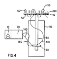
- a test sample 140 is placed in sample tube 60 and sample tube 60 is secured to vibratable member 40 using apertures 50 .
- the electrical wave generator 10 When activated, the electrical wave generator 10 generates electrical energy in the form of a wave having a selected frequency and amplitude. The amplitude of this wave is then increased after passing through amplifier 70. As a result, the energy of the electrical wave is increased. However, the frequency of the electrical wave remains the same.
- the amplified electrical wave 150 is transferred to the vibrational element 20 through, for example, wire 160 connected to amplifier 70 and vibrational element 20. Vibrational element 20 converts the electrical energy into vibrational energy and emits vibrational wave 170.
- Vibrational wave 170 propagates along shaft 30 toward vibratable member 40 and contacts vibratable member 40 at a point where vibratable member 40 and shaft 30 are joined. Vibrational wave 170 is converted to standing sonic wave 130 which traverses plate 40 and contacts sample tubes 60 to thereby sonicate test sample 140. After sonication is complete, typically after about 2 minutes more typically after 10 minutes, electrical wave generator 10 can be turned off which thereby dissipates the waves propagating through the system.
- waves transmitted by the vibrating element contact the vibratable member and are transformed into a standing sonic wave.
- Sample tubes are therefore contacted with a wave that does not directly emanate from the vibrating element. Rather, the sample tubes are contacted by the standing sonic wave which is a wave created by the vibratable member and distinct from the wave created by the vibrating element. Such a wave can have a frequency greater than that emitted by the vibrating elements.
- the sonicator herein provided can be employed to sonicate and thereby lyse cells such as, for example, virus or bacteria which may be present in a test sample.
- cells Upon lysing, cells release intracellular components (including nucleic acids) into the surrounding test sample.
- Nucleic acids released into the surrounding test sample can be detected by amplifying the released nucleic acid or fragments thereof, and detecting amplified product, if any.
- Methods of amplifying and detecting nucleic acid sequences are well known in the art. For example, the commercially available LCx® System (Abbott Laboratories) can be employed to amplify and detect nucleic acid sequences which are released according to the present invention.
- Exemplary amplification reactions which can be employed to amplify nucleic acid sequences include, but are not limited to the ligase chain reaction (LCR) described in EP-A-320,308 and EP-A-439,182 or the polymerase chain reaction (PCR) described in U.S. Patents 4,683,195 and 4,683,202.
- LCR ligase chain reaction
- PCR polymerase chain reaction
- the sonicator employed for the Examples was essentially the same as that shown in Figure 2.
- a function generator Philips model PM15132; Phillips Corp.; Eindhoven, Netherlands
- the amplifier was connected to a pair of doughnut-shaped lead zirconium niobate piezoelectric vibrating elements (available from Etalon Inc., Riverside IN) with wires and connections (Etalon).
- the vibrating elements had an inherent frequency of 29 KHz and were stacked and sandwiched between aluminum discs such that the vibrating element closest to a circular plate was 55 mm ( ⁇ /4 wavelengths) from the plate.
- the plate was circular piece of aluminum having an 88.9 mm diameter and a thickness of 3.1 mm. 10 circular threaded holes, 6.35 mm in diameter, were each centered at 31.75 mm from the sample plate's center to form a ring of holes around the outer periphery of the plate. Concentrically from the first 10 holes, another circle of 8 threaded holes were centered at 19.05 mm from the center of the sample plate.
- the plate was secured to the shaft by threading one end of the shaft and the center of the plate such that the plate and shaft could be screwed together.
- the shaft was secured to the aluminum disc in the same manner.
- Finely divided sand was spread across the sonicator's plate, and the electrical wave generator was activated.
- the sonicator's electrical wave generator was set such that the waves produced by the amplifier, and therefore transferred to the vibrating elements, had a frequency of 39 KHz and 50 watts.
- the electrical wave generator Upon activation of the electrical wave generator, the sand migrated to form three concentric circles across the surface of the plate.
- One circle of sand was located between the plate's edge and the outermost ring of sample tube holders, another was located between the rings of sample tube holders and a third cirde of sand was located between the plates center and the inner-most ring of sample tube holders.
- the areas where the sand migrated were indicative of the areas where the standing sonic wave had minimum energy.
- the span between the circles of sand were representative of 1/2 of the wavelength of the standing sonic wave generated across the plate.
- the distance between the concentric circles was 13 mm. Accordingly, a full standing sonic wavelength was 0.026 m.
- the speed of sound in aluminum in a transverse direction is 3040 m/second (s) and the speed of sound in aluminum in a longitudinal direction is 6420 m/s.
- the frequency of the standing sonic wave across the plate was thus 3040 (m/s)/0.026 (m) for the transverse frequency.
- the transverse frequency i.e. the frequency of the standing sonic wave
- the frequency of the standing sonic wave which is the wave used to sonicate the samples, is at least more than twice the frequency of the wave inputted to the vibrating elements.
- the power/unit volume that a sample experiences as a result of sonication with the instant sonicator was calculated.
- a volume of water and glass beads were sonicated and the temperature change in the water and glass beads was used to determine the amount of power supplied/ml.
- the calories absorbed was the sum of (0.5 ml)(1 gram/ml)(47°C)(1 calorie/°C) or 23.5 calories or 98.2 Joules.
- the Joules experienced by the glass beads was calculated to be 11.8 Joules. Accordingly, the total Joules experienced by the beads and water was 110 Joules. Dividing by the time that power was being delivered to the system (120 seconds), the total watts delivered to the water and beads were 0.917 watts. Last, dividing the watts by the amount of sample (0.5 ml), it was determined that the power density experienced by the sample was 1.83 watts/ml.
- nucleic acid was released from Mycobacterium tuberculosis strain H37Ra (Mtb) using the present sonicator. After sonicating a test sample of Mtb, LCR was run on an aliquot of the test sample to determine the extent of cell disruption caused by the sonicator.
- Mtb Mycobacterium tuberculosis strain H37Ra
- a 4x10 7 colony forming unit (cfu)/ml culture of Mtb was diluted with distilled water to a concentration of 40 cfu/ml.
- 250 ⁇ l of the diluted culture and 100 ⁇ l of 10 mM tris(hydroxymethyl)aminomethane (Tris®), 1mM Ethylenediamine tetraacetic acid (EDTA), pH 8 buffer (TE buffer) was then placed in 1.5 ml sample tubes (Sarstedt). These tubes were then inserted into the sample tube holders by twisting the tubes through the threaded holes in the plate. Sample tubes were placed opposite each other and in cases where an odd number of tubes were to be sonicated, a blank tube containing TE buffer was placed opposite the odd sample tube.
- the electrical wave generator and amplifier were set to operate at a frequency of 29 KHz. Additionally, the duty rating was set at 50%.
- the power supplied to the plate, as well as the sonication times varied. Actual power and times are shown, along with the data from this experiment, in Table 1.
- the power was read as the forward power from the amplifier's panel after minimizing the reflected power from the transducer to as close to zero as possible. After sonicating the various samples, 35 ⁇ l of the sonicated mixture was added to reaction tubes for amplification of released DNA.
- Released DNA was amplified using gap filling LCR essentially as set forth in U.S. Patent No. 5,427,930 and U.S. Patent Application No. 08/242,403 filed May 13, 1994.
- the target sequence is set forth herein as SEQ. ID. NO. 1 and the probes employed to amplify the target sequence are set forth herein as SEQ. ID. NO. 2-SEQ. ID. NO. 5.
- Opposite ends of adjacent probes were labeled with carbazole and adamantane haptens to facilitate detection of the amplified sequences.
- Amplified sequences were detected with an LCx® analyzer (Abbott Laboratories; Abbott Park, IL) using anti-carbazole coated microparticles and anti-adamantane antibody conjugated to alkaline phosphatase.
- the LCx® indicated the presence of the sequences with a rate based signal measured in counts/second/second (c/s/s).
- Table 1 shows the results of this experiment. As shown by Table 1, the sonicator disrupted Mtb at the various powers and times tested. Power Output (watts) Sonication Time (minutes) LCx® Rate (c/s/s) S.D. (c/s/s) 10 5 616 198 10 10 1126 127 10 15 1322 42 20 5 1101 160 20 10 1253 170 20 15 1265 68 35 5 1286 157 35 10 1812 76 35 15 1826 42 50 5 1803 58 50 10 1821 45 50 15 1500 81
- Example 3 The same samples, procedure and sonicator used in Example 3 were employed in this Example, except that 80 ⁇ l of glass beads (150-212 micrometers diameter - Product No. 1145; Sigma Chemical Co.; St. Louis, Mo.) were added to the sample tubes prior to sonication.
- the power outputs, sonication times and results for this experiment are presented in Table 2 below. As shown by Table 2, in the presence of the glass beads, the sonicator disrupted cells at the various powers and times tested. Power Output (watts) Sonication Time (minutes) LCx® Rate (c/s/s) S.D.
- Example 3 100 ⁇ l of a 3x10 8 cfu/ml culture of Mtb, 80 ⁇ l of glass beads (150-212 micrometers diameter - Product No. 1145; Sigma Chemical Co.; St. Louis, Mo.), and 170 ⁇ l of TE buffer were placed in sample tubes and sonicated as in Example 3 with the standing sonic wave sonicator. However, sonication was at 50 watts for periods of 5, 10, and 30 minutes.
- Bath sonication was performed with a Branson Instrument Model No. 2200 (Branson Ultrasonics Corp.; Danberry, CT). Samples were prepared as above for the standing sonic wave sonicator, except that 100 ⁇ l of glass beads were added to the sample tubes.
- the bath sonicator contained about 1.5 liters of water, preheated to 65° Celsius (C), and presonicated for 30 minutes. Sample tubes were immersed in the bath and sonicated for 20 minutes.
- the Bead beater experiments were performed by mixing 100 ⁇ l of a 3x10 8 cfu/ml culture of Mtb with 300 ⁇ l of glass beads in sample tubes.
- the tubes were loaded into a sample holder and inserted into the bead beater (Nouvas Manufacturing Technology Co.; Orange, CA). Bead beating took place for 5 minutes.
- a standing sonic wave sonicator having a larger circular plate than that previously described and a tracking loop was used to sonicate Mtb samples.
- the sample plate was 127 mm in diameter and 2.38 mm thick with 20 threaded holes drilled 53.7 mm from the center of the plate and substantially equidistant from each other.
- This standing wave sonicator's ability to sonicate Mtb was compared to other methods of cell lysis including bath sonication (as in Example 5), bead beating (as in Example 5) and boiling. All methods were tested with equal initial concentrations of Mtb (approximately 1 cfu/ml). Prior to sonication with the standing sonic wave sonicator, the Mtb cells were centrifuged and the resulting pellet was resuspended in TE buffer.
- Bath sonication and bead beating were performed as described in Example 5.
- Standing wave sonication took place for 5 minutes at a frequency of 34 KHz and 100 watts of power.
- the duty cycle was set at 50%. Samples were placed in boiling water for 15 minutes according to the boiling method of,cell lysis.
- Table 4 shows the results from the standing wave sonication
- Table 5 shows the results from the bead beating
- Table 6 shows the results from the bath sonication.
- the average LCx® rate for the boiling method of lysis was 292 with a standard deviation (S.D.) of 121.
- Example 7 a standing sonic wave sonicator equipped with a 127 mm x 127 mm x 3.18 mm square plate was used to sonicate Mtb. Threaded holes 50 were drilled in plate 40 in the pattern shown in Figure 5 where the site of the plate and shaft connection 180 is also shown. Sample preparation, sonication and nucleic acid detection procedures set forth in Example 3 were also employed in this Example. Table 7 presents the results obtained for 40 samples sonicated in this manner. As shown by Table 7, a standing sonic wave sonicator equipped with a square plate effectively disrupted Mtb cells.
- the resulting pellet was resuspended in sodium phosphate buffer (67 mM) containing 0.2 % bovine serum albumin and the resuspended pellet was neutralized with hydrochloric acid (HCl).
- HCl hydrochloric acid
- Part of each sample was used for cell culturing of Mtb, a second part was used for acid fast stain (AFS), and a third part (375 ⁇ l) was used for the LCR amplification.
- the portion used for LCR amplification was diluted in 1 ml of TE buffer and centrifuged for 20 minutes at 3000 x g.
- the resulting pellet was resuspended in 250 ⁇ l of TE buffer, and 30 ⁇ l of glass beads (150-212 micrometers diameter - Product No.
- Example 1145 Sigma Chemical Co.; St. Louis, Mo.
- All samples that were sonicated were sonicated for 10 minutes, at a power of 50 watts, a frequency of' 34 KHz, and a duty rating of 50%.
- 25 ⁇ l of the sonicated samples was amplified using LCR as in Example 3 and detected as in Example 3.
- Table 8 shows the results obtained from 8 samples using the cell culture, AFS and LCR based detection of Mtb. The remaining samples were negative for Mtb by all methods.
- the AFS Index was based upon Conventions from the American Thoracic Society, "Diagnostic Standards and Classifications of Tuberculosis", Am. Rev. Respir. Dis., 1990; 142 :725-735. According to this index, a value of "1+” indicates the presence of Mtb and a value of "2+” indicates a greater Mtb load than the 1+ value. According to this method of Mtb detection, 4 samples were positive.
- the culture colony counts ranged from confluency to negative. Where it was possible to count the individual colonies in culture, those counts were represented and placed in the ranges shown in Table 8. According to this method of Mtb detection, 5 samples were positive. All samples determined to be positive by this method were determined to be contaminated with Mtb.
- the mycobacterium species was determined by a Accuprobe® Mtb probe kit (Gen-Probe Inc., San Diego, CA).
- the standing sonic wave sonicator and LCR amplification of an Mtb target sequence indicated that 8 samples were positive for Mtb. Additionally, this method detected Mtb in all samples which were positive by either culture or AFS. Patients whose samples were positive by this method of Mtb detection and no others were treated for Mtb infection. Hence, the standing sonic wave sonicator was effective at releasing nucleic acid from Mtb.
Landscapes
- Chemical & Material Sciences (AREA)
- Life Sciences & Earth Sciences (AREA)
- Engineering & Computer Science (AREA)
- Health & Medical Sciences (AREA)
- Bioinformatics & Cheminformatics (AREA)
- Organic Chemistry (AREA)
- Zoology (AREA)
- Wood Science & Technology (AREA)
- Biotechnology (AREA)
- Genetics & Genomics (AREA)
- Biomedical Technology (AREA)
- General Health & Medical Sciences (AREA)
- Tropical Medicine & Parasitology (AREA)
- Medicinal Chemistry (AREA)
- Microbiology (AREA)
- Mycology (AREA)
- Chemical Kinetics & Catalysis (AREA)
- Biochemistry (AREA)
- General Engineering & Computer Science (AREA)
- Virology (AREA)
- Mechanical Engineering (AREA)
- Apparatus Associated With Microorganisms And Enzymes (AREA)
- Measurement Of Mechanical Vibrations Or Ultrasonic Waves (AREA)
- Headphones And Earphones (AREA)
- Apparatuses For Generation Of Mechanical Vibrations (AREA)
- Physical Or Chemical Processes And Apparatus (AREA)
- Percussion Or Vibration Massage (AREA)
Claims (11)
- Eine Vorrichtung zum Beschallen von Proben, die folgendes umfasst:dadurch gekennzeichnet, dass der Abstand n + ¼ oder n + ¾ der Wellenlänge des Vibrationselements (20) beträgt, worin n irgendeine ganze Zahl ist, und worin das vibrierende Glied (40) über eine Mehrzahl an Stellen (50) verfügt, um die Proben (60) zu sichern, die sich an Stellen maximaler Energie am vibrierenden Glied (40) befinden.(a) einen elektrischen Wellengenerator (10);(b) ein Vibrationselement (20), das elektrisch mit dem elektrischen Wellengenerator (10) verbunden ist, wobei das Vibrationselement (20) mit einer Welle (30) verbunden ist; und(c) ein vibrierendes Glied (40), das quer an der Welle (30) in einem Abstand zum Vibrationselement (20) gesichert wird,
- Die Vorrichtung nach Anspruch 1, worin sich die Stellen (50) zum Sichern der Proben (60) in einem Abstand von der Welle (30) weg angeordnet sind, der gleich n + ¼ oder n + ¾ der Wellenlänge einer stehenden Schallwelle am vibrierenden Glied (40) ist, worin n irgendeine ganze Zahl ist.
- Die Vorrichtung der Ansprüche 1 oder 2, worin das vibrierende Glied (40) eine Platte ist.
- Die Vorrichtung nach Anspruch 3, worin die Platte kreisförmig ist.
- Die Vorrichtung nach einem oder mehreren der Ansprüche 1 bis 4, die weiterhin einen Verstärker (70) umfasst, der elektrisch mit dem elektrischen Wellengenerator (10) und dem Vibrationselement (20) verbunden ist.
- Die Vorrichtung nach einem oder mehreren der Ansprüche 1 bis 4, die weiterhin einen Verstärker (70) umfasst, der elektrisch mit dem elektrischen Wellengenerator (10) verbunden ist, und eine Rückkopplungs-Phasengelichlauf-Schleife umfasst, die mit dem Verstärker (70) und dem Vibrationselement (20) operativ verbunden wird.
- Die Vorrichtung nach einem oder mehreren der Ansprüche 1-6, die weiterhin ein weiteres Vibrationselement (100) umfasst, das über dem Vibrationselement (20) gestapelt angeordnet ist.
- Ein Verfahren zum Beschallen von Proben, das folgende Schritte umfasst:(a) das Umwandeln einer elektrischen Energiewelle in eine Vibrationsenergiewelle;(b) das Bereitstellen eines vibrierenden Glieds (40) in einem Abstand zum Ursprung der Vibrationsenergiewelle, worin der Abstand n + ¼ oder n + ¾ der Wellenlänge der Vibrationsenergiewelle beträgt und n irgendeine ganze Zahl ist;(c) das In-Kontakt-bringen des vibrierenden Glieds (40) mit der Vibrationsenergiewelle, um eine stehende Schallwelle am vibrierenden Glied (40) zu erzeugen;(d) das Anordnen der Proben (60) an den Stellen auf dem vibrierenden Glied (40) der maximaler Energie der stehenden Schallwelle; und(e) das In-Kontakt-bringen der Proben (60) mit der stehenden Schallwelle.
- Das Verfahren nach Anspruch 8, worin der Kontaktpunkt des vibrierenden Glieds (40) mit der Vibrationsenergiewelle einen Ursprung der stehenden Schallwelle bestimmt, und das weiterhin den Schritt zum Anordnen der Proben (60) in einem Abstand weg vom Ursprung der stehenden Schallwelle umfasst, der gleich n + ¼ oder n + ¾ der Wellenlänge der stehenden Schallwelle ist, worin n irgendeine ganze Zahl ist.
- Das Verfahren nach den Ansprüchen 8 oder 9, worin das vibrierende Glied (40) eine kreisförmige Platte ist.
- Das Verfahren nach einem oder mehreren der Ansprüche 8 bis 10, worin die stehende Schallwelle eine Frequenz hat, die größer als etwa 100 kHz ist.
Applications Claiming Priority (5)
| Application Number | Priority Date | Filing Date | Title |
|---|---|---|---|
| US564995 | 1990-08-09 | ||
| US36264094A | 1994-12-22 | 1994-12-22 | |
| US362640 | 1994-12-22 | ||
| US08/564,995 US6071480A (en) | 1994-12-22 | 1995-12-21 | Method for generating a standing sonic wave, methods of sonication with a standing sonic wave, and a standing sonic wave sonicator |
| PCT/US1995/016810 WO1996019301A1 (en) | 1994-12-22 | 1995-12-22 | Method for generating a standing sonic wave, methods of sonication with a standing sonic wave, and a standing sonic wave sonicator |
Publications (2)
| Publication Number | Publication Date |
|---|---|
| EP0799098A1 EP0799098A1 (de) | 1997-10-08 |
| EP0799098B1 true EP0799098B1 (de) | 2002-04-03 |
Family
ID=27001749
Family Applications (1)
| Application Number | Title | Priority Date | Filing Date |
|---|---|---|---|
| EP95943966A Expired - Lifetime EP0799098B1 (de) | 1994-12-22 | 1995-12-22 | Verfahren zum erzeugen von stehenden schallwellen,beschallungsverfahren mit einer stehenden schallwelle,und eine stehende schallwelle verwendende beschaller |
Country Status (7)
| Country | Link |
|---|---|
| US (1) | US6071480A (de) |
| EP (1) | EP0799098B1 (de) |
| JP (1) | JPH10511305A (de) |
| AT (1) | ATE215406T1 (de) |
| DE (1) | DE69526250T2 (de) |
| ES (1) | ES2177679T3 (de) |
| WO (1) | WO1996019301A1 (de) |
Families Citing this family (19)
| Publication number | Priority date | Publication date | Assignee | Title |
|---|---|---|---|---|
| FR2791697B1 (fr) * | 1999-04-01 | 2003-02-28 | Biomerieux Sa | Appareil et procede de lyse par ultrasons de cellules biologiques |
| WO2001046714A1 (en) * | 1999-12-10 | 2001-06-28 | Misonix Incorporated | Ultrasonic horn assembly |
| US6578659B2 (en) | 2000-12-01 | 2003-06-17 | Misonix Incorporated | Ultrasonic horn assembly |
| US20020159917A1 (en) * | 2001-04-27 | 2002-10-31 | Swart Sally Kay | System and method for cleaning, high level disinfection, or sterilization of medical or dental instruments or devices |
| DE10148916A1 (de) * | 2001-10-04 | 2003-04-17 | Beatrix Christa Meier | Ultraschallvorrichtung |
| US6819027B2 (en) * | 2002-03-04 | 2004-11-16 | Cepheid | Method and apparatus for controlling ultrasonic transducer |
| US7004282B2 (en) * | 2002-10-28 | 2006-02-28 | Misonix, Incorporated | Ultrasonic horn |
| GB2405640A (en) * | 2003-09-08 | 2005-03-09 | Secr Defence | Apparatus for ultrasonic microbial disruption |
| US7931611B2 (en) * | 2005-03-23 | 2011-04-26 | Misonix, Incorporated | Ultrasonic wound debrider probe and method of use |
| GB2425974A (en) * | 2005-05-09 | 2006-11-15 | Orion Diagnostica Oy | Sonication of a medium |
| EP1902433A1 (de) * | 2005-07-01 | 2008-03-26 | M. G. International | Einrichtung zum detektieren eines in einen pool fallenden körpers |
| US7943352B2 (en) * | 2006-03-29 | 2011-05-17 | Bacoustics, Llc | Apparatus and methods for vaccine development using ultrasound technology |
| US20080058775A1 (en) * | 2006-08-29 | 2008-03-06 | Darian Alexander L | Ultrasonic debrider probe and method of use |
| JP5655232B2 (ja) * | 2008-12-05 | 2015-01-21 | ビオカルティ ナームローゼ フェノーツハップBiocartis NV | 搬送ヒータを有する熱サイクルシステム |
| KR20120018153A (ko) * | 2009-04-14 | 2012-02-29 | 비오까르띠 에스아 | 집속된 음향 에너지에 의한 샘플의 처리 |
| US8518681B2 (en) * | 2009-12-04 | 2013-08-27 | Sound Surgical Technologies Llc | Selective lysing of cells using ultrasound |
| US10280448B2 (en) * | 2012-08-30 | 2019-05-07 | Kanagawa University | Nucleic acid denaturation apparatus, method for denaturing nucleic acid and method for amplifying nucleic acid |
| US9587236B2 (en) | 2013-01-18 | 2017-03-07 | Folim G. Halaka | Continuous sonication for biotechnology applications and biofuel production |
| FR3036799A1 (fr) | 2015-05-28 | 2016-12-02 | Biomerieux Sa | Dispositif pour la preparation d'echantillons biologiques |
Family Cites Families (14)
| Publication number | Priority date | Publication date | Assignee | Title |
|---|---|---|---|---|
| GB938163A (en) * | 1960-09-20 | 1963-10-02 | Boots Pure Drug Co Ltd | Improvements in or relating to particle size reduction or cellular disruption |
| US4571087A (en) * | 1983-03-22 | 1986-02-18 | Board Of Regents, University Of Texas System | Array sonicator apparatus for automated sample preparation |
| CA1296604C (en) * | 1986-03-20 | 1992-03-03 | Kathleen Murphy | Method for releasing rna and dna from cells |
| DD284131A7 (de) * | 1987-07-10 | 1990-11-07 | �����@�������`����k�� | Verfahren und vorrichtung zur herstellung bioaktiver suspensionen |
| US4941134A (en) * | 1988-04-01 | 1990-07-10 | Arc Sonics Inc. | Sonic generator |
| US4983523A (en) * | 1988-04-08 | 1991-01-08 | Gene-Trak Systems | Methods for preparing sample nucleic acids for hybridization |
| JP2671135B2 (ja) * | 1988-08-01 | 1997-10-29 | 東湘電機株式会社 | 細胞の超音波破砕装置 |
| US5180363A (en) * | 1989-04-27 | 1993-01-19 | Sumitomo Bakelite Company Company Limited | Operation device |
| JPH02286149A (ja) * | 1989-04-27 | 1990-11-26 | Sumitomo Bakelite Co Ltd | 外科手術装置 |
| FR2671743B1 (fr) * | 1991-01-17 | 1993-06-18 | Duburque Dominique | Dispositif de mise en vibration ultrasonique d'une structure non accordee. |
| US5185242A (en) * | 1991-06-24 | 1993-02-09 | Becton Dickinson And Company | Method for lysing mycobacteria using achromopeptidase |
| WO1993003150A1 (en) * | 1991-07-31 | 1993-02-18 | Amoco Corporation | Simultaneous shear and denaturation of nucleic acids |
| DE4241154C1 (de) * | 1992-12-07 | 1994-03-17 | Lancaster Group Ag | Verfahren zum Aufschluß von Zelldispersionen oder Zellsuspensionen mittels Ultraschallbehandlung zwecks Gewinnung von Zellinhaltsstoffen |
| US5614501A (en) * | 1994-07-21 | 1997-03-25 | The University Of Montana | Compositions and methods for animal husbandry and for treating gastrointestinal disorders |
-
1995
- 1995-12-21 US US08/564,995 patent/US6071480A/en not_active Expired - Lifetime
- 1995-12-22 AT AT95943966T patent/ATE215406T1/de not_active IP Right Cessation
- 1995-12-22 JP JP8520021A patent/JPH10511305A/ja not_active Ceased
- 1995-12-22 ES ES95943966T patent/ES2177679T3/es not_active Expired - Lifetime
- 1995-12-22 EP EP95943966A patent/EP0799098B1/de not_active Expired - Lifetime
- 1995-12-22 DE DE69526250T patent/DE69526250T2/de not_active Expired - Lifetime
- 1995-12-22 WO PCT/US1995/016810 patent/WO1996019301A1/en not_active Ceased
Also Published As
| Publication number | Publication date |
|---|---|
| ES2177679T3 (es) | 2002-12-16 |
| ATE215406T1 (de) | 2002-04-15 |
| DE69526250D1 (de) | 2002-05-08 |
| JPH10511305A (ja) | 1998-11-04 |
| EP0799098A1 (de) | 1997-10-08 |
| DE69526250T2 (de) | 2002-11-28 |
| WO1996019301A1 (en) | 1996-06-27 |
| US6071480A (en) | 2000-06-06 |
Similar Documents
| Publication | Publication Date | Title |
|---|---|---|
| US6071480A (en) | Method for generating a standing sonic wave, methods of sonication with a standing sonic wave, and a standing sonic wave sonicator | |
| EP1879688B1 (de) | Schallbehandlung eines mediums | |
| Kuznetsova et al. | Applications of ultrasound streaming and radiation force in biosensors | |
| Belgrader et al. | A minisonicator to rapidly disrupt bacterial spores for DNA analysis | |
| US9321050B2 (en) | Microfluidic ultrasonic particle separators with engineered node locations and geometries | |
| Coakley | Ultrasonic separations in analytical biotechnology | |
| Gaida et al. | Selective retention of viable cells in ultrasonic resonance field devices | |
| US7108137B2 (en) | Method and apparatus for separating particles by size | |
| US5059294A (en) | Method for separating nucleic acids and nucleic acid probes | |
| KR20120018153A (ko) | 집속된 음향 에너지에 의한 샘플의 처리 | |
| Sin et al. | In situ electrokinetic enhancement for self-assembled-monolayer-based electrochemical biosensing | |
| US20050053996A1 (en) | Molecular detection and assay by electrobiochip micro-array | |
| US8169122B1 (en) | Ultra sonic release of DNA or RNA | |
| KR20230034202A (ko) | 세포 용해 시스템 및 방법 | |
| GB2403729A (en) | Sonicator device and method | |
| CA2207601A1 (en) | Method for generating a standing sonic wave, methods of sonification with a standing sonic wave, and a standing sonic wave sonicator | |
| Cousins et al. | Clarification of plasma from whole human blood using ultrasound | |
| JP4644198B2 (ja) | 超音波細菌破壊装置 | |
| Hanna et al. | Increased alkaline phosphatase isoforms in autoimmune diseases | |
| US8409801B2 (en) | Method and apparatus for material separation using acoustic energy | |
| US11674928B2 (en) | Detecting nucleic acids in impure samples with an acoustic wave sensor | |
| US11215622B2 (en) | Generation of cfDNA reference material | |
| CN1421692A (zh) | 利用电生物芯片微阵列的分子检测和分析 | |
| JPH10108698A (ja) | 超音波を利用する核酸ハイブリダイゼーション反応方法およびそのための装置 | |
| WO2001067084A1 (fr) | Procede de mesure de l'activite biologique et dispositif associe |
Legal Events
| Date | Code | Title | Description |
|---|---|---|---|
| PUAI | Public reference made under article 153(3) epc to a published international application that has entered the european phase |
Free format text: ORIGINAL CODE: 0009012 |
|
| 17P | Request for examination filed |
Effective date: 19970710 |
|
| AK | Designated contracting states |
Kind code of ref document: A1 Designated state(s): AT BE CH DE ES FR GB IT LI NL |
|
| 17Q | First examination report despatched |
Effective date: 19980921 |
|
| GRAG | Despatch of communication of intention to grant |
Free format text: ORIGINAL CODE: EPIDOS AGRA |
|
| GRAG | Despatch of communication of intention to grant |
Free format text: ORIGINAL CODE: EPIDOS AGRA |
|
| GRAH | Despatch of communication of intention to grant a patent |
Free format text: ORIGINAL CODE: EPIDOS IGRA |
|
| GRAH | Despatch of communication of intention to grant a patent |
Free format text: ORIGINAL CODE: EPIDOS IGRA |
|
| REG | Reference to a national code |
Ref country code: GB Ref legal event code: IF02 |
|
| GRAA | (expected) grant |
Free format text: ORIGINAL CODE: 0009210 |
|
| AK | Designated contracting states |
Kind code of ref document: B1 Designated state(s): AT BE CH DE ES FR GB IT LI NL |
|
| REF | Corresponds to: |
Ref document number: 215406 Country of ref document: AT Date of ref document: 20020415 Kind code of ref document: T |
|
| REG | Reference to a national code |
Ref country code: CH Ref legal event code: EP |
|
| REF | Corresponds to: |
Ref document number: 69526250 Country of ref document: DE Date of ref document: 20020508 |
|
| REG | Reference to a national code |
Ref country code: CH Ref legal event code: NV Representative=s name: A. BRAUN, BRAUN, HERITIER, ESCHMANN AG PATENTANWAE |
|
| ET | Fr: translation filed | ||
| REG | Reference to a national code |
Ref country code: ES Ref legal event code: FG2A Ref document number: 2177679 Country of ref document: ES Kind code of ref document: T3 |
|
| PLBE | No opposition filed within time limit |
Free format text: ORIGINAL CODE: 0009261 |
|
| STAA | Information on the status of an ep patent application or granted ep patent |
Free format text: STATUS: NO OPPOSITION FILED WITHIN TIME LIMIT |
|
| 26N | No opposition filed |
Effective date: 20030106 |
|
| PGFP | Annual fee paid to national office [announced via postgrant information from national office to epo] |
Ref country code: AT Payment date: 20031104 Year of fee payment: 9 |
|
| PGFP | Annual fee paid to national office [announced via postgrant information from national office to epo] |
Ref country code: NL Payment date: 20031110 Year of fee payment: 9 |
|
| PGFP | Annual fee paid to national office [announced via postgrant information from national office to epo] |
Ref country code: BE Payment date: 20040114 Year of fee payment: 9 |
|
| PG25 | Lapsed in a contracting state [announced via postgrant information from national office to epo] |
Ref country code: AT Free format text: LAPSE BECAUSE OF NON-PAYMENT OF DUE FEES Effective date: 20041222 |
|
| PG25 | Lapsed in a contracting state [announced via postgrant information from national office to epo] |
Ref country code: BE Free format text: LAPSE BECAUSE OF NON-PAYMENT OF DUE FEES Effective date: 20041231 |
|
| BERE | Be: lapsed |
Owner name: *ABBOTT LABORATORIES Effective date: 20041231 |
|
| PG25 | Lapsed in a contracting state [announced via postgrant information from national office to epo] |
Ref country code: NL Free format text: LAPSE BECAUSE OF NON-PAYMENT OF DUE FEES Effective date: 20050701 |
|
| NLV4 | Nl: lapsed or anulled due to non-payment of the annual fee |
Effective date: 20050701 |
|
| PGFP | Annual fee paid to national office [announced via postgrant information from national office to epo] |
Ref country code: CH Payment date: 20061026 Year of fee payment: 12 |
|
| PGFP | Annual fee paid to national office [announced via postgrant information from national office to epo] |
Ref country code: ES Payment date: 20061214 Year of fee payment: 12 |
|
| PGFP | Annual fee paid to national office [announced via postgrant information from national office to epo] |
Ref country code: IT Payment date: 20061231 Year of fee payment: 12 |
|
| BERE | Be: lapsed |
Owner name: *ABBOTT LABORATORIES Effective date: 20041231 |
|
| REG | Reference to a national code |
Ref country code: CH Ref legal event code: PFA Owner name: ABBOTT LABORATORIES Free format text: ABBOTT LABORATORIES#CHAD 0377/AP6D-2, 100 ABBOTT PARK ROAD#ABBOTT PARK, ILLINOIS 60064-3500 (US) -TRANSFER TO- ABBOTT LABORATORIES#CHAD 0377/AP6D-2, 100 ABBOTT PARK ROAD#ABBOTT PARK, ILLINOIS 60064-3500 (US) |
|
| REG | Reference to a national code |
Ref country code: CH Ref legal event code: PL |
|
| PG25 | Lapsed in a contracting state [announced via postgrant information from national office to epo] |
Ref country code: LI Free format text: LAPSE BECAUSE OF NON-PAYMENT OF DUE FEES Effective date: 20071231 Ref country code: CH Free format text: LAPSE BECAUSE OF NON-PAYMENT OF DUE FEES Effective date: 20071231 |
|
| PGFP | Annual fee paid to national office [announced via postgrant information from national office to epo] |
Ref country code: FR Payment date: 20080627 Year of fee payment: 13 |
|
| REG | Reference to a national code |
Ref country code: ES Ref legal event code: FD2A Effective date: 20071224 |
|
| PG25 | Lapsed in a contracting state [announced via postgrant information from national office to epo] |
Ref country code: ES Free format text: LAPSE BECAUSE OF NON-PAYMENT OF DUE FEES Effective date: 20071224 |
|
| PG25 | Lapsed in a contracting state [announced via postgrant information from national office to epo] |
Ref country code: IT Free format text: LAPSE BECAUSE OF NON-PAYMENT OF DUE FEES Effective date: 20071222 |
|
| REG | Reference to a national code |
Ref country code: FR Ref legal event code: ST Effective date: 20090831 |
|
| PG25 | Lapsed in a contracting state [announced via postgrant information from national office to epo] |
Ref country code: FR Free format text: LAPSE BECAUSE OF NON-PAYMENT OF DUE FEES Effective date: 20081231 |
|
| REG | Reference to a national code |
Ref country code: DE Ref legal event code: R082 Ref document number: 69526250 Country of ref document: DE Representative=s name: SCHIEBER - FARAGO, DE |
|
| REG | Reference to a national code |
Ref country code: GB Ref legal event code: 732E Free format text: REGISTERED BETWEEN 20131205 AND 20131211 |
|
| REG | Reference to a national code |
Ref country code: DE Ref legal event code: R082 Ref document number: 69526250 Country of ref document: DE Representative=s name: SCHIEBER - FARAGO, DE Effective date: 20131210 Ref country code: DE Ref legal event code: R081 Ref document number: 69526250 Country of ref document: DE Owner name: ABBOTT MOLECULAR INC. (N.D.GES.D. STAATES DELA, US Free format text: FORMER OWNER: ABBOTT LABORATORIES, ABBOTT PARK, ILL., US Effective date: 20131210 Ref country code: DE Ref legal event code: R081 Ref document number: 69526250 Country of ref document: DE Owner name: ABBOTT MOLECULAR INC. (N.D.GES.D. STAATES DELA, US Free format text: FORMER OWNER: ABBOTT LABORATORIES, ABBOTT PARK, US Effective date: 20131210 |
|
| PGFP | Annual fee paid to national office [announced via postgrant information from national office to epo] |
Ref country code: GB Payment date: 20141124 Year of fee payment: 20 |
|
| PGFP | Annual fee paid to national office [announced via postgrant information from national office to epo] |
Ref country code: DE Payment date: 20141222 Year of fee payment: 20 |
|
| REG | Reference to a national code |
Ref country code: DE Ref legal event code: R071 Ref document number: 69526250 Country of ref document: DE |
|
| REG | Reference to a national code |
Ref country code: GB Ref legal event code: PE20 Expiry date: 20151221 |
|
| PG25 | Lapsed in a contracting state [announced via postgrant information from national office to epo] |
Ref country code: GB Free format text: LAPSE BECAUSE OF EXPIRATION OF PROTECTION Effective date: 20151221 |