EP0799111B1 - Zones recyclables de meules - Google Patents
Zones recyclables de meules Download PDFInfo
- Publication number
- EP0799111B1 EP0799111B1 EP95938460A EP95938460A EP0799111B1 EP 0799111 B1 EP0799111 B1 EP 0799111B1 EP 95938460 A EP95938460 A EP 95938460A EP 95938460 A EP95938460 A EP 95938460A EP 0799111 B1 EP0799111 B1 EP 0799111B1
- Authority
- EP
- European Patent Office
- Prior art keywords
- abrasive
- zone
- grinding
- plastic material
- disk according
- Prior art date
- Legal status (The legal status is an assumption and is not a legal conclusion. Google has not performed a legal analysis and makes no representation as to the accuracy of the status listed.)
- Expired - Lifetime
Links
- 239000000463 material Substances 0.000 claims description 45
- 239000004033 plastic Substances 0.000 claims description 45
- 229920003023 plastic Polymers 0.000 claims description 45
- 239000006061 abrasive grain Substances 0.000 claims description 18
- 239000011230 binding agent Substances 0.000 claims description 15
- 230000007704 transition Effects 0.000 claims description 15
- 238000000034 method Methods 0.000 claims description 12
- 238000004519 manufacturing process Methods 0.000 claims description 11
- 239000000919 ceramic Substances 0.000 claims description 9
- 239000011347 resin Substances 0.000 claims description 9
- 229920005989 resin Polymers 0.000 claims description 9
- 238000005266 casting Methods 0.000 claims description 8
- 239000002826 coolant Substances 0.000 claims description 8
- 229910052751 metal Inorganic materials 0.000 claims description 8
- 239000002184 metal Substances 0.000 claims description 8
- VYPSYNLAJGMNEJ-UHFFFAOYSA-N Silicium dioxide Chemical group O=[Si]=O VYPSYNLAJGMNEJ-UHFFFAOYSA-N 0.000 claims description 7
- 239000000945 filler Substances 0.000 claims description 7
- 238000004064 recycling Methods 0.000 claims description 7
- 239000000203 mixture Substances 0.000 claims description 6
- 230000008569 process Effects 0.000 claims description 6
- HBMJWWWQQXIZIP-UHFFFAOYSA-N silicon carbide Chemical compound [Si+]#[C-] HBMJWWWQQXIZIP-UHFFFAOYSA-N 0.000 claims description 6
- 229910010271 silicon carbide Inorganic materials 0.000 claims description 6
- KXGFMDJXCMQABM-UHFFFAOYSA-N 2-methoxy-6-methylphenol Chemical compound [CH]OC1=CC=CC([CH])=C1O KXGFMDJXCMQABM-UHFFFAOYSA-N 0.000 claims description 5
- 239000012779 reinforcing material Substances 0.000 claims description 5
- 229920001568 phenolic resin Polymers 0.000 claims description 4
- 239000005011 phenolic resin Substances 0.000 claims description 4
- 230000002787 reinforcement Effects 0.000 claims description 4
- 229910052580 B4C Inorganic materials 0.000 claims description 3
- MCMNRKCIXSYSNV-UHFFFAOYSA-N ZrO2 Inorganic materials O=[Zr]=O MCMNRKCIXSYSNV-UHFFFAOYSA-N 0.000 claims description 3
- INAHAJYZKVIDIZ-UHFFFAOYSA-N boron carbide Chemical compound B12B3B4C32B41 INAHAJYZKVIDIZ-UHFFFAOYSA-N 0.000 claims description 3
- 229910001651 emery Inorganic materials 0.000 claims description 3
- 239000004744 fabric Substances 0.000 claims description 3
- 239000002223 garnet Substances 0.000 claims description 3
- RVTZCBVAJQQJTK-UHFFFAOYSA-N oxygen(2-);zirconium(4+) Chemical compound [O-2].[O-2].[Zr+4] RVTZCBVAJQQJTK-UHFFFAOYSA-N 0.000 claims description 3
- 229920001169 thermoplastic Polymers 0.000 claims description 3
- 239000004416 thermosoftening plastic Substances 0.000 claims description 3
- 239000006004 Quartz sand Chemical group 0.000 claims description 2
- INJRKJPEYSAMPD-UHFFFAOYSA-N aluminum;silicic acid;hydrate Chemical compound O.[Al].[Al].O[Si](O)(O)O INJRKJPEYSAMPD-UHFFFAOYSA-N 0.000 claims description 2
- 239000004927 clay Substances 0.000 claims description 2
- KZHJGOXRZJKJNY-UHFFFAOYSA-N dioxosilane;oxo(oxoalumanyloxy)alumane Chemical compound O=[Si]=O.O=[Si]=O.O=[Al]O[Al]=O.O=[Al]O[Al]=O.O=[Al]O[Al]=O KZHJGOXRZJKJNY-UHFFFAOYSA-N 0.000 claims description 2
- 239000003822 epoxy resin Substances 0.000 claims description 2
- 239000011521 glass Substances 0.000 claims description 2
- LNEPOXFFQSENCJ-UHFFFAOYSA-N haloperidol Chemical compound C1CC(O)(C=2C=CC(Cl)=CC=2)CCN1CCCC(=O)C1=CC=C(F)C=C1 LNEPOXFFQSENCJ-UHFFFAOYSA-N 0.000 claims description 2
- 239000011256 inorganic filler Substances 0.000 claims description 2
- 239000010443 kyanite Substances 0.000 claims description 2
- 229910052850 kyanite Inorganic materials 0.000 claims description 2
- 229910052863 mullite Inorganic materials 0.000 claims description 2
- 239000010434 nepheline Substances 0.000 claims description 2
- 229910052664 nepheline Inorganic materials 0.000 claims description 2
- 239000012766 organic filler Substances 0.000 claims description 2
- 229920000647 polyepoxide Polymers 0.000 claims description 2
- 229920001225 polyester resin Polymers 0.000 claims description 2
- 239000004645 polyester resin Substances 0.000 claims description 2
- 239000004576 sand Substances 0.000 claims description 2
- 239000010435 syenite Substances 0.000 claims description 2
- 229920001187 thermosetting polymer Polymers 0.000 claims description 2
- PNEYBMLMFCGWSK-UHFFFAOYSA-N Alumina Chemical compound [O-2].[O-2].[O-2].[Al+3].[Al+3] PNEYBMLMFCGWSK-UHFFFAOYSA-N 0.000 claims 3
- 238000007669 thermal treatment Methods 0.000 claims 2
- 239000000314 lubricant Substances 0.000 claims 1
- 238000000227 grinding Methods 0.000 description 154
- 235000013339 cereals Nutrition 0.000 description 14
- 239000000835 fiber Substances 0.000 description 10
- 238000005520 cutting process Methods 0.000 description 7
- 230000002093 peripheral effect Effects 0.000 description 5
- 239000011148 porous material Substances 0.000 description 5
- 229910052593 corundum Inorganic materials 0.000 description 4
- 239000010431 corundum Substances 0.000 description 4
- 239000012744 reinforcing agent Substances 0.000 description 4
- 229910000831 Steel Inorganic materials 0.000 description 3
- 239000000853 adhesive Substances 0.000 description 3
- 230000001070 adhesive effect Effects 0.000 description 3
- 239000011248 coating agent Substances 0.000 description 3
- 238000011109 contamination Methods 0.000 description 3
- 239000005068 cooling lubricant Substances 0.000 description 3
- 238000009826 distribution Methods 0.000 description 3
- TWNQGVIAIRXVLR-UHFFFAOYSA-N oxo(oxoalumanyloxy)alumane Chemical compound O=[Al]O[Al]=O TWNQGVIAIRXVLR-UHFFFAOYSA-N 0.000 description 3
- ISWSIDIOOBJBQZ-UHFFFAOYSA-N phenol group Chemical group C1(=CC=CC=C1)O ISWSIDIOOBJBQZ-UHFFFAOYSA-N 0.000 description 3
- 239000004848 polyfunctional curative Substances 0.000 description 3
- 238000012545 processing Methods 0.000 description 3
- 239000010453 quartz Substances 0.000 description 3
- 239000010959 steel Substances 0.000 description 3
- 230000004913 activation Effects 0.000 description 2
- 238000000576 coating method Methods 0.000 description 2
- 150000001875 compounds Chemical class 0.000 description 2
- 239000010432 diamond Substances 0.000 description 2
- 229910003460 diamond Inorganic materials 0.000 description 2
- 238000005516 engineering process Methods 0.000 description 2
- 235000013312 flour Nutrition 0.000 description 2
- -1 polyethylene Polymers 0.000 description 2
- 238000002360 preparation method Methods 0.000 description 2
- 239000002699 waste material Substances 0.000 description 2
- 239000010456 wollastonite Chemical group 0.000 description 2
- 229910052882 wollastonite Inorganic materials 0.000 description 2
- 239000005995 Aluminium silicate Substances 0.000 description 1
- 229910052582 BN Inorganic materials 0.000 description 1
- PZNSFCLAULLKQX-UHFFFAOYSA-N Boron nitride Chemical compound N#B PZNSFCLAULLKQX-UHFFFAOYSA-N 0.000 description 1
- 229920002430 Fibre-reinforced plastic Polymers 0.000 description 1
- 239000004698 Polyethylene Substances 0.000 description 1
- 239000004743 Polypropylene Substances 0.000 description 1
- 239000003082 abrasive agent Substances 0.000 description 1
- 230000001464 adherent effect Effects 0.000 description 1
- 235000012211 aluminium silicate Nutrition 0.000 description 1
- 238000004873 anchoring Methods 0.000 description 1
- 238000005452 bending Methods 0.000 description 1
- 230000015572 biosynthetic process Effects 0.000 description 1
- 239000003795 chemical substances by application Substances 0.000 description 1
- 238000004140 cleaning Methods 0.000 description 1
- 238000010276 construction Methods 0.000 description 1
- 229920001971 elastomer Polymers 0.000 description 1
- 230000007613 environmental effect Effects 0.000 description 1
- 239000011151 fibre-reinforced plastic Substances 0.000 description 1
- 238000011049 filling Methods 0.000 description 1
- 238000010304 firing Methods 0.000 description 1
- 239000008187 granular material Substances 0.000 description 1
- 238000005470 impregnation Methods 0.000 description 1
- 230000006872 improvement Effects 0.000 description 1
- NLYAJNPCOHFWQQ-UHFFFAOYSA-N kaolin Chemical compound O.O.O=[Al]O[Si](=O)O[Si](=O)O[Al]=O NLYAJNPCOHFWQQ-UHFFFAOYSA-N 0.000 description 1
- 239000007791 liquid phase Substances 0.000 description 1
- 238000003754 machining Methods 0.000 description 1
- 230000007246 mechanism Effects 0.000 description 1
- 238000002844 melting Methods 0.000 description 1
- 230000008018 melting Effects 0.000 description 1
- 150000002739 metals Chemical class 0.000 description 1
- 238000000465 moulding Methods 0.000 description 1
- 230000000704 physical effect Effects 0.000 description 1
- 229920000573 polyethylene Polymers 0.000 description 1
- 229920001155 polypropylene Polymers 0.000 description 1
- 229920001296 polysiloxane Polymers 0.000 description 1
- 239000000843 powder Substances 0.000 description 1
- 238000003825 pressing Methods 0.000 description 1
- 230000002265 prevention Effects 0.000 description 1
- 239000002994 raw material Substances 0.000 description 1
- 230000008929 regeneration Effects 0.000 description 1
- 238000011069 regeneration method Methods 0.000 description 1
- 239000002990 reinforced plastic Substances 0.000 description 1
- 238000012958 reprocessing Methods 0.000 description 1
- 238000007788 roughening Methods 0.000 description 1
- 239000005060 rubber Substances 0.000 description 1
- 238000005488 sandblasting Methods 0.000 description 1
- 150000004756 silanes Chemical class 0.000 description 1
- 239000002689 soil Substances 0.000 description 1
- 238000005476 soldering Methods 0.000 description 1
- 239000007921 spray Substances 0.000 description 1
- 239000004575 stone Substances 0.000 description 1
- 238000003860 storage Methods 0.000 description 1
- 238000005728 strengthening Methods 0.000 description 1
- 239000000126 substance Substances 0.000 description 1
- 238000003466 welding Methods 0.000 description 1
Images

Classifications
-
- B—PERFORMING OPERATIONS; TRANSPORTING
- B24—GRINDING; POLISHING
- B24D—TOOLS FOR GRINDING, BUFFING OR SHARPENING
- B24D5/00—Bonded abrasive wheels, or wheels with inserted abrasive blocks, designed for acting only by their periphery; Bushings or mountings therefor
- B24D5/16—Bushings; Mountings
-
- B—PERFORMING OPERATIONS; TRANSPORTING
- B24—GRINDING; POLISHING
- B24D—TOOLS FOR GRINDING, BUFFING OR SHARPENING
- B24D18/00—Manufacture of grinding tools or other grinding devices, e.g. wheels, not otherwise provided for
-
- B—PERFORMING OPERATIONS; TRANSPORTING
- B24—GRINDING; POLISHING
- B24D—TOOLS FOR GRINDING, BUFFING OR SHARPENING
- B24D7/00—Bonded abrasive wheels, or wheels with inserted abrasive blocks, designed for acting otherwise than only by their periphery, e.g. by the front face; Bushings or mountings therefor
- B24D7/14—Zonally-graded wheels; Composite wheels comprising different abrasives
-
- B—PERFORMING OPERATIONS; TRANSPORTING
- B24—GRINDING; POLISHING
- B24D—TOOLS FOR GRINDING, BUFFING OR SHARPENING
- B24D7/00—Bonded abrasive wheels, or wheels with inserted abrasive blocks, designed for acting otherwise than only by their periphery, e.g. by the front face; Bushings or mountings therefor
- B24D7/16—Bushings; Mountings
Definitions
- the invention relates to grinding wheels Abrasive grain and an inorganic or organic binder for this in an outer peripheral zone and thus in Contact non-grinding zone in contact to accommodate Fasteners, in particular clamping flanges, a process for the production of the grinding wheels and a method for recycling the used grinding wheels.
- grinding wheels In the production of ceramic or phenolic resin-bound
- grinding wheels these holistically from the known corundums or, for example Manufacture silicon carbide.
- finer or harder non-grinding zones in phenolic resin-bonded or ceramic-bonded grinding wheels.
- This non-grinding zones consist of the abrasive grain itself and selected binders and are usually created in one operation with the outer wear layer.
- the in the case of phenolic resin-bonded grinding discs the inner zones are said to Increase strength or only allow the necessary Fracture speeds of the grinding wheels reached can be.
- DE 42 44 476 A1 relates to a master blade for circular saw blades and / or cut-off wheels, consisting of a circular, at least partially embedded with one Fiber reinforced plastic material existing disc body.
- the fibers are in several superimposed, cohesively connected, flat, circular and Disc body arranged in concentric fiber layers.
- the fibers are in a - related on the disc body - at least approximately radially in the direction rectilinear and in one across the circumference even distribution arranged.
- the fibers In a second type of Fiber layer, the fibers have at least approximately circular, substantially concentric with the disc body Course, using the two types of fiber layers one depending on the size of the disc body selected distribution are arranged in the disc body.
- the cutting disc therefore always consists of three parts; the inner reinforced plastic master sheet, which on the circumference attached holding device made of steel and the cutting segments. Connection mechanisms are, for example, welding, Soldering and clamping. With the cutting discs described here it is necessary that the outer cutting active segments are wider in the axial direction than the master sheet described and the holding device.
- a circumferential grinding wheel is known from DE-C-27 40 891, which consists of an inner hub part and an outer, one
- the grinding ring consists of a wheel part carrying a grinding wheel, with hub and rim over preloaded - and thus the Performing the function of "spokes” - wires, fibers or threads are interconnected.
- the "spokes” are in Plastic embedded. In addition to the “spokes” is said in the plastic is a common fabric mat Fiber reinforcement must be embedded.
- DE 43 11 529 A1 describes a grinding wheel described in particular a cutting wheel, the one ring-cylindrical inner support body made of metal and a this surrounding slip ring, which with each other are connected.
- the slip ring is on both sides in the direction the common axis over the support body.
- the slip ring can be sanded completely.
- the supporting body is reusable or at least recyclable.
- US-A-2,475,517 describes a grinding wheel, in particular a cutting disc comprising abrasive grain made of thermoplastic bound material and a non-grinding zone with at least one hole, the non-grinding zone from a reinforcing material containing organic Plastic material is made.
- grinding wheels namely So-called grinding cups and screw-on grinding wheels Soils or fine layers in use, some of which are made of Plastic.
- these are generally used for recording of threaded pieces.
- the object of the present invention is therefore in Manufacture of inexpensive grinding wheels through provision of reusable and recyclable non-grinding zones to hold fasteners, especially flanges.
- the above-mentioned object is achieved according to the invention by grinding wheels with an outside diameter of 200 to 1600 mm and 10 to 600 mm wide, including abrasive grain Aluminum oxide, zirconium dioxide, silicon carbide, boron carbide, Garnet, emery and flint or a mixture of these and inorganic ceramic binder for this in one outer grinding zone (1) and one in contact with it non-grinding zone (2) with at least one hole for Inclusion of clamping flanges, the non-grinding active Zone (2) from a structure-sealed, filler and optionally Organic plastic material containing reinforcing agents consists.
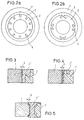
- FIG. 1 shows an example of a grinding wheel according to the invention shown with an inner bore and clamping flanges.
- the grinding wheel is over the non-grinding active zone 2 held on the shaft by the clamping flanges.
- the size the non-grinding zone 2 corresponds essentially to the External dimensions of the clamping flanges.
- Radially from the inside out a transition zone follows the non-grinding zone 2 3, which essentially consists of abrasive grain, that however within this area 3 by the organic Plastic material is impregnated to make a firm connection between the non-grinding zone 2 and the grinding zone To create 1.
- the outer grinding zone 1 is thus complete for processing the object to be ground Available. If the grinding wheel to the desired minimum is ground off, which is made of grinding and safety technology This grinding wheel can meet requirements can be recycled with the aid of the present invention.
- the non-grinding zone 2 is removed from the adherent Abrasive grain freed and an outer grinding zone 1 in itself manufactured in a known manner. Then the non-grinding active Zone 2 centered within the outer grinding zone 1 and the remaining space between the non-grinding active Zone 2 and the outer grinding zone 1 with a plastic material filled out and possibly a temperature treatment subject, you get a new grinding wheel, the non-grinding active zone 2 of a recycling is fed.
- the grinding wheel shown in Figure 1 has a transition zone 3 between the outer grinding zone 1 and not active grinding zone 2, which consists essentially of the abrasive grain and the plastic material of the non-grinding zone (2) exists.
- a transition zone 3 is in principle not absolutely necessary in the sense of the present invention.
- transition zone 3 is a necessary one Depth does not exceed, otherwise the grinding wheel, due to contamination by the plastic material cannot be used optimally.
- High clamping forces are possible with the aid of the present invention, in particular in the production of soft grinding wheels, for example hardness A (extremely soft) to J (medium), with a modulus of elasticity according to Grindo Sonic from 10 to 39 kN / mm 2 (depending on the grain size) or highly porous grinding media with a pore volume of more than 50%, which can be held with the aid of the present invention with secure clamping forces.
- Mounting devices for grinding wheels usually consist of two flanges with ring-shaped wings, between which the grinding wheel is held non-positively.
- Flanges according to DIN 6375 are mainly used in industry. They have a mounting flange and a counter flange, between which the grinding wheel can be clamped and balanced outside the machine.
- the clamping force required to clamp a grinding wheel On the one hand, it must be so large that the pane is under maximum operating load not to slide between the Flanges coming; on the other hand, the clamping force only be chosen so large that it certainly won't damage to the grinding wheel and thus a risk of breakage can come.
- the present invention now enables an uncomplicated one Construction of grinding wheel clamping devices and drives, so that a central shaft can often be dispensed with and the screw connection in the non-grinding zone 2 is possible.
- a dovetail-shaped training can Abrasive discs from 20 mm width can be used usually immediately when the blanks are pressed, i.e. without later mechanical processing can be attached, for example for grinding discs, cylindrical grinding discs and centerless discs.
- Grooves 4,5, both perpendicular 4 and in certain angular position 5, if necessary, both in the Grinding wheels, as well as in the non-grinding active to be cast Zone 2 are cut using a diamond saw as in Fig.2a and 2b shown.
- Grinding wheels in particular non-grinding zone 2
- channels running radially from the inside out which allow coolants or cooling lubricants, due to the centrifugal force of the rotating grinding wheel directly into the working area of the grinding wheels transport, instead of with high pressure against the air cushion to spray the rotating disc.
- the Structural density i.e. the ratio of pore volume to Grain and binder volume is not in the prior art clearly defined. Numbers indicate with increasing number towards a more open structure.
- pore formers are used in addition to hollow spherical grains, which evaporate when the grinding wheels burn or burn.
- This material of the non-grinding zone 2 must be designed in such a way that contamination with the Coolants or coolants are practically avoided, otherwise recycling is not an option. Minor soiling of the surface can, however, be avoided further, for example mechanically or by cleaning, be removed.
- the abrasive grain of the outer grinding zone 1 made of aluminum oxide, zirconium dioxide, silicon carbide, Boron carbide, garnet, emery, flint stone, cubic boron nitride and diamond or a mixture of these. Especially in this sense, aluminum oxide (corundum) and Silicon carbide.
- the binder of the outer grinding zone 1 corresponds to that in Inorganic or organic known in the art Binders.
- a distinction is usually made between ceramic, phenolic (or other resins) rubber, and / or magnesite-bonded grinding wheel, so that the physical Properties of the manufacturers are completely different. This Accordingly, it particularly affects the strength data the clearly defined clamping forces.
- the proportion of binder is particularly preferably the outer one Grinding zone 1 1 to 50 wt .-% and is selected in particular from ceramic binders, in particular mullite, kyanite, Nepheline, syenite, clay, kaolin and fries or a mixture the same and from binders containing phenolic resin.
- Active grinding zone 2 preferably consists of thermoplastic or thermosetting plastic materials, in particular from single or multi-component casting resins such as Polyester resins or epoxy resins. Choosing the appropriate Materials is essentially due to the breaking strength, the structural tightness and the storage stability without major Loss of strength determines which is crucial for the Prevention of contamination from coolants or coolants is. Accordingly, the non-grinding active Zone 2 has the lowest possible porosity at least Have surface. With a total service life of up to 3 Months, up to 12 cycles are possible.
- Break-proof plastic materials as they are in the sense of the present Invention for the non-grinding zone 2 required are usually associated with high costs. Accordingly, it is in the sense of the present invention desirable, a high proportion, for example 5 to 200 Parts by weight, in particular 10 to 50 parts by weight, inorganic or organic fillers, especially sand, quartz sand, Wollastonite or abrasive grain residues, based on 100 parts by weight Add plastic material.
- the abrasive grain remains preferably obtained from abrasive residues.
- organically coated quartz flours such as wollastonite with doping of 1 to 100%, in particular 10 to 50% in general for increasing strength of plastic parts.
- organic Coating agents can be silanes, for example are used, which are commercially available in a variety are. The selection is made according to the type of plastic material and of hardening. Activation is also possible in this context the transition zone 3 by an additional organic Coating.
- the temperature of the hardening of the plastic materials can also an influence on the strength of the non-grinding zone Have 2.
- a hardening of cold hardening plastic materials at room temperature is preferred according to the invention, since this is the Stress relief favors. Possible tensions when curing are degraded in the viscous state, provided that the curing at room temperature. The hardening shrinkage is in the liquid phase.
- the plastic material of non-abrasive zone 2 contains reinforcing agents.
- these include, in particular, reinforcements, in particular glass and / or wire mesh or the plastic material to understand added, strengthening fibers.
- the size of the non-grinding zone 2 of the invention Grinding wheels should be at least the outside diameter of the Fasteners, especially the clamping flanges. This ensures that within the bracing area of the non-grinding zone 2 a load distribution occurs as evenly as possible.
- the non-grinding active zone 2 is usually used slightly larger than the outside diameter of the fasteners be made, or as large as the Permits the use of the outer grinding zone 1.
- grinding wheels are on the Basis of ceramic or resin-bonded abrasive grains on a scale of 200 to 1600 mm outside diameter, 10 to 600 mm width and all common holes, for example 32 to 550 mm, in particular 51 to 305 mm, excellently producible.
- the term includes grinding wheels in the sense of the present invention in particular one-sided or recessed on both sides and / or on one side and / or on both sides tapered grinding wheels, cylindrical cup wheels, cylindrical Double cups, tapered cups, grinding plates, glued or screwed grinding wheels with Carrying disks, glued or screwed grinding cylinders.
- a further embodiment of the present invention is the process for the preparation of the invention Grinding wheels characterized in that one a) the outer grinding zone 1 in a manner known per se manufactures and b) the area of non-grinding zone 2 with a structural seals, filler and optionally reinforcing agent filled plastic material and if necessary subjected to a temperature treatment.
- the area of the non-grinding zone 2 with the Pour plastic material and if necessary by Harden exposure to elevated temperature is particularly preferred.
- non-grinding zone pour out in multiple layers, for example two layers.
- resins are used, if necessary at room temperature poured and hardened, very good physical Possess properties.
- the viscosity of the plastic material to be filled in that may contain filler should be set that at least part of the plastic material penetrates into the outer grinding zone 1 and thus a transition zone 3 trains that an intimate connection between the non-grinding zone 2 and the outer grinding zone 1 for Provides.
- a newer outer peripheral zone 1 in itself known manner and a new, custom-made or used inner zone 2 within the outer grinding zone 1 centered and the remaining space 2 'between the non-grinding zone 2 and the outer grinding zone 1 with a plastic material 2 'that meets the above requirements to the plastic material of the non-abrasive Zone 2 corresponds, filled, as in Fig. 3 and 4, in particular Embodiment is shown and optionally a temperature treatment subject.
- the space 2 'to be filled is preferably designed such that as shown in Figures 3 and 4, since the undercut a particularly good interlocking of the materials causes. It is an alternative to the method described here here, too, the filling in layers as described above possible.
- a grinding wheel with a not active grinding zone 2 shown next to the teeth 3 and 4 is designed such that the height the inner zone 2, 2 'somewhat above the level of the grinding active Zone 1 and the transition zone 3 protrude and therefore in each Level of recycling processed and new by the Plastic material can be poured out.
- This area is in particular 0.5 to 3 mm, preferably 0.5 to 1.5 mm.
- the level of the inner non-grinding zone 2 above that Level of active grinding zone 1 and transition zone 1 of course also a one-sided projection with the reachable by the same means.
- the following exemplary embodiment illustrates the method for the production of the grinding wheel, the grinding wheel thus obtained themselves and their recycling.
- a grinding wheel according to the invention was produced initially in the manufacture of the ceramic bonded outer zone in a manner known per se. With the user became the greatest possible Degree of wear of the grinding wheel set so determine the raw bore of the outer zone.
- the non-grinding zone 2 was cut to a diameter of 255 mm, the transition zone 3 including the non-grinding active Zone 2 set to an area of 270 mm.
- the dimensions of the blank were 353 x 15 x 253 mm with a recess of 260 x 2.5 mm compared to 353 x 15 x 147 mm usual manufacturing.
- a volume comparison of the previous volume of 1213 cm 3 corresponds to a volume of 706.9 cm 3 corresponding to 58.3% by volume of the previous grinding wheel in a production according to the invention.
- the blank of 353 x 15 x 253 mm was planned on both sides 13 mm to achieve flat side surfaces. Then followed machining the bore to a dimension of 255 +/- 0.5 mm. For this purpose, the grinding wheel was placed on a CNC lathe on the outside clamped in the three-jaw chuck and the hole with 2 roughing chips drilled to size.
- the present blank now had the dimensions of 353 x 13 x 255 mm with a recess of 260 x 1.5 mm.
- a metallic core was first used, too Plastics or the like, with a correspondingly smooth surface (Roughness ⁇ 0.3 ⁇ m) on a flat surface made of suitable Material, for example plastic or metal centered, placed at right angles.
- suitable Material for example plastic or metal centered, placed at right angles.
- the surface of the core and the The plate was coated with a release agent.
- Corresponding complete plastic parts are also possible, for example silicone, polyethylene or polypropylene molded parts.
- a metal adhesive from the company was available as casting resin - WEVO-Chemie with the resin types WEVO® metal adhesive A with a Mallison viscosity of 5.5 s and WEVO® Hardener B263 with a Mallison viscosity of 1.5 s.
- W10 quartz powder and classified were used as fillers Abrasive residues from mechanical processing used in the grain size range 100 to 280.
- the pourable mass was poured 0.6 to 0.8 mm above the level and after 24 hours the blank is demolded, the one after another could be machined for 48 hours.
- the casting compound was with the viscosity of 65 set in this way s penetrated 3 to 4 mm deep into the panes according to Mallison.
Landscapes
- Engineering & Computer Science (AREA)
- Mechanical Engineering (AREA)
- Manufacturing & Machinery (AREA)
- Polishing Bodies And Polishing Tools (AREA)
Claims (13)
- Meule possédant un diamètre extérieur de 200 à 1600 mm et une largeur de 10 à 600 mm, comprenant un grain abrasif en oxyde d'aluminium, en bioxyde de zirconium, en carbure de silicium, en carbure de bore, en grenat, en émeri et en silex ou un mélange de ces substances, et un liant céramique minéral ou organique pour cette substance, dans une zone extérieure de meulage (1), et une zone (2) non active pour le meulage et située en contact avec la précédente et comportant au moins un perçage pour loger des brides de serrage, la zone (2) non active du point de vue du meulage étant réalisée en une matière plastique organique à structure dense, contenant une charge et éventuellement des moyens de renfort.
- Meule selon la revendication 1, caractérisée en ce que la zone extérieure de meulage (1) et la zone (2) non active pour le meulage sont en contact par l'intermédiaire d'une zone de jonction (3) qui possède des particules abrasives, un liant et une matière plastique.
- Meule selon la revendication 1, caractérisée en ce que le pourcentage de liant de la zone extérieure de meulage (1) est compris entre 1 et 50 % en poids et que le liant céramique est choisi parmi la mullite, la cyanite, la néphéline, la syénite, l'argile, le kaolin et des frittes ainsi qu'un mélange de ces substances.
- Meule selon la revendication 1, caractérisée en ce que le pourcentage du liant dans la zone extérieure (1) de la meule est compris entre 1 et 50 % en poids et est choisi notamment parmi des liants contenant une résine phénolique.
- Meule selon la revendication 1 ou 2, caractérisée en ce que la matière plastique de la zone (2) non active pour le meulage et/ou la zone de jonction (3) est choisie parmi les matières thermoplastiques ou les matières plastiques thermodurcissables, notamment des résines de coulée à un constituant ou à plusieurs constituants, telles que des résines polyester ou des résines époxy.
- Meule selon la revendication 5, caractérisée en ce que la matière plastique de la zone (2) non active pour le meulage contient 5 à 200 parties en poids, notamment 10 à 50 parties en poids de substance de charge minérales ou organiques, notamment du sable, du sable quartzeux, de la farine de quartz ou des restes de pellicules abrasives, rapportées à 100 parties en poids de matière plastique.
- Meule selon la revendication 5, caractérisée en ce que la matière plastique de la zone (2) non active pour le meulage contient, comme moyens de renforcement, des éléments d'armature, notamment un tissu de verte et/ou d'un treillis de fils ou des fibres augmentant la solidité et/ou des canaux s'étendant radialement de l'intérieur vers l'extérieur pour alimenter la zone de travail avec des fluides de refroidissement et/ou des substances lubrifiantes de refroidissement.
- Meule selon l'une des revendications 1 à 7, caractérisée en ce que la taille de la zone (2) non active pour le meulage correspond au moins au diamètre extérieur des brides de serrage.
- Meule selon l'une des revendications 1 à 8, comprenant des meules évidées d'un côté ou des deux côtés et/ou rétrécies d'un côté ou des deux côtés, des meules boisseaux droites cylindriques, des meules boisseaux cylindriques doubles, des meules boisseaux de forme conique, des meules en forme de disque, des meules collées ou vissées comportant des disques de support, et des meules cylindriques collées ou vissées.
- Meule selon l'une des revendications 1 à 9, caractérisée en ce que la zone intérieure (2) non active pour le meulage possède des géométriques (4) et (5) pour son engrènement avec la zone de jonction (3) ou la zone extérieure de meulage (1).
- Procédé pour fabriquer des meules selon l'une des revendications 1 à 10, caractérisé en cea) qu'on fabrique la zone extérieure de meulage (1), etb) qu'on remplit la partie correspondant à la zone (2) non active pour le meulage, par une matière plastique à structure dense contenant une charge et éventuellement des moyens de renforcement et qu'on la soumet éventuellement à un traitement thermique.
- Procédé selon la revendication 11, caractérisé en ce qu'on coule la matière plastique dans la partie correspondant à la zone (2) non active pour le meulage et qu'on la fait durcir éventuellement sous l'action d'une température accrue.
- Procédé pour réutiliser des meules selon l'une des revendications 1 à 10, caractérisé en ce qu'on enlève complètement la zone extérieure de meulage (1) et la zone de jonction éventuellement présente (3), de la surface de la zone (2) non active du point de vue du meulage, qu'on fabrique de façon connue une nouvelle zone extérieure de meulage (1), qu'on centre la zone utilisée (2), non active pour le meulage, à l'intérieur de la zone extérieure de meulage (1) et qu'on remplit l'espace intercalaire subsistant entre la zone (2) non active pour le meulage et la zone extérieure de meulage (1) par une matière plastique à structure dense contenant une charge et éventuellement des moyens de renfort, et qu'on la soumet éventuellement à un traitement thermique.
Applications Claiming Priority (3)
| Application Number | Priority Date | Filing Date | Title |
|---|---|---|---|
| DE4446591A DE4446591A1 (de) | 1994-12-24 | 1994-12-24 | Recyclefähige Schleifkörperzonen |
| DE4446591 | 1994-12-24 | ||
| PCT/EP1995/004595 WO1996020070A1 (fr) | 1994-12-24 | 1995-11-22 | Zones recyclables de meules |
Publications (2)
| Publication Number | Publication Date |
|---|---|
| EP0799111A1 EP0799111A1 (fr) | 1997-10-08 |
| EP0799111B1 true EP0799111B1 (fr) | 1999-03-24 |
Family
ID=6537115
Family Applications (1)
| Application Number | Title | Priority Date | Filing Date |
|---|---|---|---|
| EP95938460A Expired - Lifetime EP0799111B1 (fr) | 1994-12-24 | 1995-11-22 | Zones recyclables de meules |
Country Status (4)
| Country | Link |
|---|---|
| EP (1) | EP0799111B1 (fr) |
| DE (2) | DE4446591A1 (fr) |
| ES (1) | ES2129238T3 (fr) |
| WO (1) | WO1996020070A1 (fr) |
Cited By (1)
| Publication number | Priority date | Publication date | Assignee | Title |
|---|---|---|---|---|
| WO2010126934A3 (fr) * | 2009-04-30 | 2011-03-03 | Saint-Gobain Abrasives, Inc. | Article abrasif présentant une rétention améliorée des grains et des performances améliorées |
Families Citing this family (4)
| Publication number | Priority date | Publication date | Assignee | Title |
|---|---|---|---|---|
| WO1998021009A1 (fr) * | 1996-11-13 | 1998-05-22 | Rappold International Sales Ag | Corps abrasif et son procede de fabrication |
| US6988937B2 (en) * | 2002-04-11 | 2006-01-24 | Saint-Gobain Abrasives Technology Company | Method of roll grinding |
| DE102010006250A1 (de) | 2010-01-28 | 2011-08-18 | Gottfried Wilhelm Leibniz Universität Hannover, 30167 | Schleifkörper und Verfahren zur Herstellung hiervon |
| CN117961654B (zh) * | 2024-02-05 | 2024-09-24 | 广东科杰技术股份有限公司 | 一种陶瓷手表按键倒角的cnc表面抛光工艺 |
Family Cites Families (12)
| Publication number | Priority date | Publication date | Assignee | Title |
|---|---|---|---|---|
| BE543740A (fr) * | ||||
| US2479078A (en) * | 1945-10-20 | 1949-08-16 | Norton Co | Diamond abrasive wheel |
| US2475517A (en) * | 1946-08-13 | 1949-07-05 | Carborundum Co | Abrasive article of manufacture |
| US2656654A (en) * | 1950-01-06 | 1953-10-27 | Norton Co | Grinding wheel |
| FR1044067A (fr) * | 1950-11-08 | 1953-11-13 | Perfectionnements aux meules applicables notamment lorsque celles-ci doivent tourner à vitesse élevée | |
| CH577365A5 (en) * | 1973-08-22 | 1976-07-15 | Swarovski Tyrolit Schleif | High speed grinding disc - has zones of increased strength adjacent to and extending from hub bore |
| DE2740891C3 (de) * | 1977-09-10 | 1980-11-13 | Ernst 8909 Niederraunau Spielvogel | Umfangsschleifscheibe |
| DE2825576C3 (de) * | 1978-06-10 | 1981-10-29 | Burka-Kosmos GmbH Schleifscheiben und Präzisionsschleifstifte, 6000 Frankfurt | Verfahren zum Auskleiden der Bohrung einer großen Schleifscheibe |
| IT209729Z2 (it) * | 1986-02-28 | 1988-10-24 | Marmotecnica Srl | Struttura di mola cilindrica per teste di levigatura, particolarmente per pietre, marmo, granito e simili. |
| US4910924A (en) * | 1986-12-22 | 1990-03-27 | Norton Company | Composite grinding wheel |
| DE4244476A1 (de) * | 1992-12-30 | 1994-07-07 | Heinrich Mummenhoff | Stammblatt aus faserverstärktem Kunststoff für Kreissägeblätter und/oder Trennschleifscheiben |
| DE4311529A1 (de) * | 1993-02-15 | 1994-08-18 | Rueggeberg August | Schleifscheibe für handgeführte Schleifmaschinen, insbesondere Trenn-Schleifscheibe |
-
1994
- 1994-12-24 DE DE4446591A patent/DE4446591A1/de not_active Withdrawn
-
1995
- 1995-11-22 DE DE59505462T patent/DE59505462D1/de not_active Expired - Lifetime
- 1995-11-22 EP EP95938460A patent/EP0799111B1/fr not_active Expired - Lifetime
- 1995-11-22 WO PCT/EP1995/004595 patent/WO1996020070A1/fr not_active Ceased
- 1995-11-22 ES ES95938460T patent/ES2129238T3/es not_active Expired - Lifetime
Cited By (1)
| Publication number | Priority date | Publication date | Assignee | Title |
|---|---|---|---|---|
| WO2010126934A3 (fr) * | 2009-04-30 | 2011-03-03 | Saint-Gobain Abrasives, Inc. | Article abrasif présentant une rétention améliorée des grains et des performances améliorées |
Also Published As
| Publication number | Publication date |
|---|---|
| EP0799111A1 (fr) | 1997-10-08 |
| WO1996020070A1 (fr) | 1996-07-04 |
| DE59505462D1 (de) | 1999-04-29 |
| DE4446591A1 (de) | 1996-06-27 |
| ES2129238T3 (es) | 1999-06-01 |
Similar Documents
| Publication | Publication Date | Title |
|---|---|---|
| DE68919908T2 (de) | Schleifscheibe mit hoher Schlagfestigkeit zum in-situ-Schleifen von Rollen. | |
| EP1170091B1 (fr) | Outil de chanfreinage | |
| EP1812206B1 (fr) | Anneau de tronçonneuse à double dispositif de serrage médian | |
| EP0799111B1 (fr) | Zones recyclables de meules | |
| EP0523260B1 (fr) | Corps de plastique renforcé de fibres pour lames de scie circulaires ou meules tronçonneuses | |
| DE3042643A1 (de) | Schleifkoerper und verfahren zur herstellung desselben | |
| WO2015067377A1 (fr) | Outil abrasif à fibres vulcanisées | |
| EP0612586B1 (fr) | Disque abrasif pour meuleuse portative, en particulier disque de trançonnage | |
| DE102012005085A1 (de) | Werkzeug zum Bearbeiten von Materialien | |
| DE69903709T2 (de) | Schleifscheibe | |
| AT509372B1 (de) | Verbundschleifsystem | |
| WO2023233035A1 (fr) | Outil de meulage pour l'usinage de roues dentées | |
| DE19812515A1 (de) | Lamellenschleifwerkzeug | |
| DE9420676U1 (de) | Recyclefähige Schleifkörperzonen | |
| CH701596B1 (de) | Abrichtwerkzeug. | |
| EP0657251B1 (fr) | Disque abrasif de tronçonnage pour meuleuse stationnaire et sa mise en oeuvre | |
| DE29510727U1 (de) | Werkzeug, insbesondere Schleif- oder Polierteller | |
| DE19511004C1 (de) | Werkzeug mit einem Schleif- oder Polierbelag | |
| AT518251B1 (de) | Schleifscheibe | |
| EP1837123B1 (fr) | Outil destiné au traitement de surfaces et son procédé de fabrication | |
| DE4300417A1 (de) | Grundkörper für Schleifscheiben für rotierende oder schwingende Schleifwerkzeuge | |
| EP0832720A2 (fr) | Disque de meulage pour meuleuse portative, en particulier disque de tronçonnage | |
| AT502845B1 (de) | Keramisch gebundene, rotationssymmetrische schleifkörper | |
| AT509371B1 (de) | Verbundschleifsystem | |
| DE202017007262U1 (de) | Schleifscheibe und Schleifkörper, insbesondere eine rotierende Schleifscheibe |
Legal Events
| Date | Code | Title | Description |
|---|---|---|---|
| PUAI | Public reference made under article 153(3) epc to a published international application that has entered the european phase |
Free format text: ORIGINAL CODE: 0009012 |
|
| 17P | Request for examination filed |
Effective date: 19970703 |
|
| AK | Designated contracting states |
Kind code of ref document: A1 Designated state(s): DE ES FR GB IT NL |
|
| 17Q | First examination report despatched |
Effective date: 19971215 |
|
| GRAG | Despatch of communication of intention to grant |
Free format text: ORIGINAL CODE: EPIDOS AGRA |
|
| GRAG | Despatch of communication of intention to grant |
Free format text: ORIGINAL CODE: EPIDOS AGRA |
|
| GRAH | Despatch of communication of intention to grant a patent |
Free format text: ORIGINAL CODE: EPIDOS IGRA |
|
| GRAH | Despatch of communication of intention to grant a patent |
Free format text: ORIGINAL CODE: EPIDOS IGRA |
|
| GRAA | (expected) grant |
Free format text: ORIGINAL CODE: 0009210 |
|
| AK | Designated contracting states |
Kind code of ref document: B1 Designated state(s): DE ES FR GB IT NL |
|
| ITF | It: translation for a ep patent filed | ||
| REF | Corresponds to: |
Ref document number: 59505462 Country of ref document: DE Date of ref document: 19990429 |
|
| REG | Reference to a national code |
Ref country code: ES Ref legal event code: FG2A Ref document number: 2129238 Country of ref document: ES Kind code of ref document: T3 |
|
| ET | Fr: translation filed | ||
| GBT | Gb: translation of ep patent filed (gb section 77(6)(a)/1977) |
Effective date: 19990622 |
|
| PLBE | No opposition filed within time limit |
Free format text: ORIGINAL CODE: 0009261 |
|
| STAA | Information on the status of an ep patent application or granted ep patent |
Free format text: STATUS: NO OPPOSITION FILED WITHIN TIME LIMIT |
|
| 26N | No opposition filed | ||
| PGFP | Annual fee paid to national office [announced via postgrant information from national office to epo] |
Ref country code: GB Payment date: 20001102 Year of fee payment: 6 |
|
| PGFP | Annual fee paid to national office [announced via postgrant information from national office to epo] |
Ref country code: FR Payment date: 20001116 Year of fee payment: 6 |
|
| PGFP | Annual fee paid to national office [announced via postgrant information from national office to epo] |
Ref country code: ES Payment date: 20001121 Year of fee payment: 6 |
|
| PGFP | Annual fee paid to national office [announced via postgrant information from national office to epo] |
Ref country code: NL Payment date: 20001123 Year of fee payment: 6 |
|
| PG25 | Lapsed in a contracting state [announced via postgrant information from national office to epo] |
Ref country code: GB Free format text: LAPSE BECAUSE OF NON-PAYMENT OF DUE FEES Effective date: 20011122 |
|
| PG25 | Lapsed in a contracting state [announced via postgrant information from national office to epo] |
Ref country code: ES Free format text: LAPSE BECAUSE OF NON-PAYMENT OF DUE FEES Effective date: 20011123 |
|
| REG | Reference to a national code |
Ref country code: GB Ref legal event code: IF02 |
|
| PG25 | Lapsed in a contracting state [announced via postgrant information from national office to epo] |
Ref country code: NL Free format text: LAPSE BECAUSE OF NON-PAYMENT OF DUE FEES Effective date: 20020601 |
|
| GBPC | Gb: european patent ceased through non-payment of renewal fee |
Effective date: 20011122 |
|
| PG25 | Lapsed in a contracting state [announced via postgrant information from national office to epo] |
Ref country code: FR Free format text: LAPSE BECAUSE OF NON-PAYMENT OF DUE FEES Effective date: 20020730 |
|
| NLV4 | Nl: lapsed or anulled due to non-payment of the annual fee |
Effective date: 20020601 |
|
| REG | Reference to a national code |
Ref country code: FR Ref legal event code: ST |
|
| REG | Reference to a national code |
Ref country code: FR Ref legal event code: ST |
|
| REG | Reference to a national code |
Ref country code: ES Ref legal event code: FD2A Effective date: 20021213 |
|
| PG25 | Lapsed in a contracting state [announced via postgrant information from national office to epo] |
Ref country code: IT Free format text: LAPSE BECAUSE OF NON-PAYMENT OF DUE FEES;WARNING: LAPSES OF ITALIAN PATENTS WITH EFFECTIVE DATE BEFORE 2007 MAY HAVE OCCURRED AT ANY TIME BEFORE 2007. THE CORRECT EFFECTIVE DATE MAY BE DIFFERENT FROM THE ONE RECORDED. Effective date: 20051122 |
|
| PGFP | Annual fee paid to national office [announced via postgrant information from national office to epo] |
Ref country code: DE Payment date: 20101216 Year of fee payment: 16 |
|
| REG | Reference to a national code |
Ref country code: DE Ref legal event code: R119 Ref document number: 59505462 Country of ref document: DE Effective date: 20120601 |
|
| PG25 | Lapsed in a contracting state [announced via postgrant information from national office to epo] |
Ref country code: DE Free format text: LAPSE BECAUSE OF NON-PAYMENT OF DUE FEES Effective date: 20120601 |