EP0799358B1 - Systeme radiofrequence de commande a distance associe a un systeme antivol - Google Patents
Systeme radiofrequence de commande a distance associe a un systeme antivol Download PDFInfo
- Publication number
- EP0799358B1 EP0799358B1 EP95943750A EP95943750A EP0799358B1 EP 0799358 B1 EP0799358 B1 EP 0799358B1 EP 95943750 A EP95943750 A EP 95943750A EP 95943750 A EP95943750 A EP 95943750A EP 0799358 B1 EP0799358 B1 EP 0799358B1
- Authority
- EP
- European Patent Office
- Prior art keywords
- signal
- vehicle
- coded signal
- microprocessor
- coded
- Prior art date
- Legal status (The legal status is an assumption and is not a legal conclusion. Google has not performed a legal analysis and makes no representation as to the accuracy of the status listed.)
- Expired - Lifetime
Links
Images

Classifications
-
- B—PERFORMING OPERATIONS; TRANSPORTING
- B60—VEHICLES IN GENERAL
- B60R—VEHICLES, VEHICLE FITTINGS, OR VEHICLE PARTS, NOT OTHERWISE PROVIDED FOR
- B60R25/00—Fittings or systems for preventing or indicating unauthorised use or theft of vehicles
- B60R25/20—Means to switch the anti-theft system on or off
- B60R25/2063—Ignition switch geometry
-
- B—PERFORMING OPERATIONS; TRANSPORTING
- B60—VEHICLES IN GENERAL
- B60R—VEHICLES, VEHICLE FITTINGS, OR VEHICLE PARTS, NOT OTHERWISE PROVIDED FOR
- B60R25/00—Fittings or systems for preventing or indicating unauthorised use or theft of vehicles
- B60R25/01—Fittings or systems for preventing or indicating unauthorised use or theft of vehicles operating on vehicle systems or fittings, e.g. on doors, seats or windscreens
- B60R25/04—Fittings or systems for preventing or indicating unauthorised use or theft of vehicles operating on vehicle systems or fittings, e.g. on doors, seats or windscreens operating on the propulsion system, e.g. engine or drive motor
-
- G—PHYSICS
- G07—CHECKING-DEVICES
- G07C—TIME OR ATTENDANCE REGISTERS; REGISTERING OR INDICATING THE WORKING OF MACHINES; GENERATING RANDOM NUMBERS; VOTING OR LOTTERY APPARATUS; ARRANGEMENTS, SYSTEMS OR APPARATUS FOR CHECKING NOT PROVIDED FOR ELSEWHERE
- G07C9/00—Individual registration on entry or exit
- G07C9/00174—Electronically operated locks; Circuits therefor; Nonmechanical keys therefor, e.g. passive or active electrical keys or other data carriers without mechanical keys
- G07C9/00182—Electronically operated locks; Circuits therefor; Nonmechanical keys therefor, e.g. passive or active electrical keys or other data carriers without mechanical keys operated with unidirectional data transmission between data carrier and locks
-
- G—PHYSICS
- G07—CHECKING-DEVICES
- G07C—TIME OR ATTENDANCE REGISTERS; REGISTERING OR INDICATING THE WORKING OF MACHINES; GENERATING RANDOM NUMBERS; VOTING OR LOTTERY APPARATUS; ARRANGEMENTS, SYSTEMS OR APPARATUS FOR CHECKING NOT PROVIDED FOR ELSEWHERE
- G07C9/00—Individual registration on entry or exit
- G07C9/00174—Electronically operated locks; Circuits therefor; Nonmechanical keys therefor, e.g. passive or active electrical keys or other data carriers without mechanical keys
- G07C9/00182—Electronically operated locks; Circuits therefor; Nonmechanical keys therefor, e.g. passive or active electrical keys or other data carriers without mechanical keys operated with unidirectional data transmission between data carrier and locks
- G07C2009/00206—Electronically operated locks; Circuits therefor; Nonmechanical keys therefor, e.g. passive or active electrical keys or other data carriers without mechanical keys operated with unidirectional data transmission between data carrier and locks the keyless data carrier being hand operated
- G07C2009/00222—Electronically operated locks; Circuits therefor; Nonmechanical keys therefor, e.g. passive or active electrical keys or other data carriers without mechanical keys operated with unidirectional data transmission between data carrier and locks the keyless data carrier being hand operated by more than one push button
-
- G—PHYSICS
- G07—CHECKING-DEVICES
- G07C—TIME OR ATTENDANCE REGISTERS; REGISTERING OR INDICATING THE WORKING OF MACHINES; GENERATING RANDOM NUMBERS; VOTING OR LOTTERY APPARATUS; ARRANGEMENTS, SYSTEMS OR APPARATUS FOR CHECKING NOT PROVIDED FOR ELSEWHERE
- G07C9/00—Individual registration on entry or exit
- G07C9/00174—Electronically operated locks; Circuits therefor; Nonmechanical keys therefor, e.g. passive or active electrical keys or other data carriers without mechanical keys
- G07C9/00182—Electronically operated locks; Circuits therefor; Nonmechanical keys therefor, e.g. passive or active electrical keys or other data carriers without mechanical keys operated with unidirectional data transmission between data carrier and locks
- G07C2009/00261—Electronically operated locks; Circuits therefor; Nonmechanical keys therefor, e.g. passive or active electrical keys or other data carriers without mechanical keys operated with unidirectional data transmission between data carrier and locks the keyless data carrier having more than one function
-
- G—PHYSICS
- G07—CHECKING-DEVICES
- G07C—TIME OR ATTENDANCE REGISTERS; REGISTERING OR INDICATING THE WORKING OF MACHINES; GENERATING RANDOM NUMBERS; VOTING OR LOTTERY APPARATUS; ARRANGEMENTS, SYSTEMS OR APPARATUS FOR CHECKING NOT PROVIDED FOR ELSEWHERE
- G07C9/00—Individual registration on entry or exit
- G07C9/00174—Electronically operated locks; Circuits therefor; Nonmechanical keys therefor, e.g. passive or active electrical keys or other data carriers without mechanical keys
- G07C2009/00753—Electronically operated locks; Circuits therefor; Nonmechanical keys therefor, e.g. passive or active electrical keys or other data carriers without mechanical keys operated by active electrical keys
- G07C2009/00769—Electronically operated locks; Circuits therefor; Nonmechanical keys therefor, e.g. passive or active electrical keys or other data carriers without mechanical keys operated by active electrical keys with data transmission performed by wireless means
- G07C2009/00777—Electronically operated locks; Circuits therefor; Nonmechanical keys therefor, e.g. passive or active electrical keys or other data carriers without mechanical keys operated by active electrical keys with data transmission performed by wireless means by induction
-
- G—PHYSICS
- G07—CHECKING-DEVICES
- G07C—TIME OR ATTENDANCE REGISTERS; REGISTERING OR INDICATING THE WORKING OF MACHINES; GENERATING RANDOM NUMBERS; VOTING OR LOTTERY APPARATUS; ARRANGEMENTS, SYSTEMS OR APPARATUS FOR CHECKING NOT PROVIDED FOR ELSEWHERE
- G07C9/00—Individual registration on entry or exit
- G07C9/00174—Electronically operated locks; Circuits therefor; Nonmechanical keys therefor, e.g. passive or active electrical keys or other data carriers without mechanical keys
- G07C2009/00753—Electronically operated locks; Circuits therefor; Nonmechanical keys therefor, e.g. passive or active electrical keys or other data carriers without mechanical keys operated by active electrical keys
- G07C2009/00769—Electronically operated locks; Circuits therefor; Nonmechanical keys therefor, e.g. passive or active electrical keys or other data carriers without mechanical keys operated by active electrical keys with data transmission performed by wireless means
- G07C2009/00793—Electronically operated locks; Circuits therefor; Nonmechanical keys therefor, e.g. passive or active electrical keys or other data carriers without mechanical keys operated by active electrical keys with data transmission performed by wireless means by Hertzian waves
-
- G—PHYSICS
- G07—CHECKING-DEVICES
- G07C—TIME OR ATTENDANCE REGISTERS; REGISTERING OR INDICATING THE WORKING OF MACHINES; GENERATING RANDOM NUMBERS; VOTING OR LOTTERY APPARATUS; ARRANGEMENTS, SYSTEMS OR APPARATUS FOR CHECKING NOT PROVIDED FOR ELSEWHERE
- G07C9/00—Individual registration on entry or exit
- G07C9/00174—Electronically operated locks; Circuits therefor; Nonmechanical keys therefor, e.g. passive or active electrical keys or other data carriers without mechanical keys
- G07C2009/00968—Electronically operated locks; Circuits therefor; Nonmechanical keys therefor, e.g. passive or active electrical keys or other data carriers without mechanical keys shape of the data carrier
- G07C2009/00992—Electronically operated locks; Circuits therefor; Nonmechanical keys therefor, e.g. passive or active electrical keys or other data carriers without mechanical keys shape of the data carrier mechanical key
-
- G—PHYSICS
- G07—CHECKING-DEVICES
- G07C—TIME OR ATTENDANCE REGISTERS; REGISTERING OR INDICATING THE WORKING OF MACHINES; GENERATING RANDOM NUMBERS; VOTING OR LOTTERY APPARATUS; ARRANGEMENTS, SYSTEMS OR APPARATUS FOR CHECKING NOT PROVIDED FOR ELSEWHERE
- G07C9/00—Individual registration on entry or exit
- G07C9/00174—Electronically operated locks; Circuits therefor; Nonmechanical keys therefor, e.g. passive or active electrical keys or other data carriers without mechanical keys
- G07C9/00309—Electronically operated locks; Circuits therefor; Nonmechanical keys therefor, e.g. passive or active electrical keys or other data carriers without mechanical keys operated with bidirectional data transmission between data carrier and locks
Definitions
- This invention relates generally to a drive-away prevention security system associated with a vehicle and, more particularly, to a system that remotely activates certain functions of a vehicle such as a vehicle door lock and unlock, and includes a subsystem for preventing vehicle ignition by an unauthorized user.
- Remote RF keyless entry systems for activating a vehicle function, such as locking and unlocking a vehicle door, or unlocking a vehicle trunk, from a remote location are known in the art.
- Remote keyless entry systems include a portable transmitter usually configured within an ignition key of the vehicle or attached as a key fob to a key chain carrying the ignition key of the vehicle.
- a vehicle operator will press a function button associated with the transmitter a distance from the vehicle in order to remotely activate the desired vehicle function.
- the transmitter will transmit an encoded signal that is received by an RF receiver within the vehicle if the transmitter is within the operating range of the system.
- the RF receiver will decode the signal, and if the receiver interprets that a valid coded signal has been received, will cause the desired function to be performed.
- Vehicle door locks can only be limitedly successful in preventing would-be thieves from gaining access to the vehicle.
- French Patent Specification No. 2633966 describes a security system having a transponder unit including a first processor, a first oscillator circuit, a first coil and a battery, and a steering lock assembly unit including a second oscillator circuit and a second coil on a bobbin.
- the present invention provides a drive-away prevention system as defined in Claim 1 hereinafter.
- the system may include the features of any one or more of dependent Claims 2 to 19.
- a drive-away prevention vehicle security system that can be used in connection with a remote RF keyless entry system.
- a vehicle ignition key or some type of key fob, is provided that encapsulates a transmitter circuit including a microprocessor and an RF oscillator circuit.
- Push-button function switches on the ignition key activate the microprocessor so as to cause the microprocessor to transmit stored encrypted data bits to the oscillator circuit to be imposed on a carrier frequency generated by the oscillator circuit.
- the carrier frequency is transmitted by an antenna within the ignition key and is received by an RF receiver within the vehicle.
- the RF receiver includes a microprocessor that deciphers and evaluates the coded transmission, and performs the encoded function if the coded signal is valid.
- the ignition key also includes an induction coil as part of a drive-away prevention security system.
- a switch in the ignition system of the vehicle is activated that causes an ignition signal to be applied to the microprocessor within the receiver.
- the microprocessor receives the ignition signal, it transmits a signal to an oscillator circuit associated with a bobbin assembly encircling the ignition switch.
- the oscillator circuit causes power to be delivered to a coil wound on a bobbin of the bobbin assembly so as to generate a time-varying magnetic field through the coil on the bobbin.
- the magnetic field generated by the coil on the bobbin induces a current on the coil within the ignition key, which in turn activates the microprocessor within the key.
- the microprocessor within the receiver switches the signal applied to the oscillator circuit within the bobbin assembly on and off to generate a sequence of data bits.
- the microprocessor within the key deciphers the signal from the coil to determine if it is a valid signal. If the signal is valid, the microprocessor causes the oscillator circuit within the key to send the encoded signal to the receiver within the vehicle, so as to determine whether an authorized key is being inserted into the ignition switch. If the microprocessor determines that a valid key is being inserted into the ignition switch, it turns off the oscillator circuit which energizes the coil wound on the bobbin, and sends a signal to an electronic engine module to enable the vehicle to be activated.
- FIG. 1 shows a schematic block diagram of a remote keyless entry system and associated drive-away prevention security system 10 according to a preferred embodiment of the present invention.
- the system 10 includes an RF transponder unit 12 that includes an integrated circuit adaptable to be configured within the head of an ignition key (not shown in Figure 1) associated with a vehicle (not shown).
- the unit 12 includes a microprocessor 14 that is powered by a voltage V cc supplied from a battery 16 through a rectifying diode D 1 .
- a quartz crystal oscillator 18 provides a stable clock signal that controls the operation of the microprocessor 14.
- the frequency of the crystal oscillator 18 can be any frequency applicable for the purposes described herein.
- Capacitors C 3 and C 4 are connected between the input and ground, and the output and ground, respectively, of the crystal oscillator 18 in order to provide the necessary filtering, as is well understood in the art.
- First and second push-button function switches S 1 and S 2 provide signals to input pins of the microprocessor 14 that upon activation will cause the microprocessor 14 to access a stored function bit sequence to perform a predetermined function.
- An RF oscillator circuit 20 is connected to high and low RF data output pins of the microprocessor 14.
- the oscillator circuit 20 is shown here as a 433.92 MHz RF oscillator merely as an example in that other frequencies may be equally applicable.
- the RF oscillator circuit 20 will generate a carrier wave at its oscillation frequency that modulates the function bit sequence in a manner that will distinguish "0" and "1" bits so as to generate a coded signal.
- Different types of keying such as frequency shift keying, amplitude shift keying, etc., can be used by the microprocessor 14 to distinguish the "0" and “1” as is well understood in the art.
- An output of the oscillator circuit 20 is applied to an antenna 22 in order to broadcast the coded signal.
- the coded signals transmitted by the antenna 22 are received by an RF receiver and control unit 28.
- the control unit 28 is configured within the vehicle at a location that will effectively provide for receipt of the coded signal from the transponder unit 12.
- An antenna 30 associated with the unit 28 receives the coded signal from the antenna 22 and sends the coded signal to an RF receiver circuit 32.
- the RF receiver circuit 32 separates the data bits from the carrier frequency, in a manner well understood in the art, and then applies the data bit sequence to a microprocessor 34.
- the microprocessor 34 compares the data bits received from the transponder unit 12 with data bits stored in a memory device such as erasable programmable read only memory (EEPROM) 36 to determine if the received coded signal is valid.
- EEPROM erasable programmable read only memory
- the microprocessor 34 will output a signal on the appropriate lock, unlock or trunk output line to perform the particular task encoded in the signal.
- the microprocessor 34 will output a signal on the appropriate lock, unlock or trunk output line to perform the particular task encoded in the signal.
- other vehicle functions may be encoded as is desirable for a particular implementation.
- the remote keyless portion of the invention operates in the following manner.
- a vehicle operator When a vehicle operator is in the vicinity of the vehicle, he will activate one of the switches S 1 or S 2 depending on the function he wishes to be performed, such as unlocking the vehicle doors as he approaches the vehicle, or locking the vehicle doors as he walks away from the vehicle.
- the unit 12 transmits the coded signal at a high power level on the HI RF data line so that the control unit 28 will be able to receive the signal only if the unit 12 is within a predetermined range (30 feet) of the vehicle.
- the microprocessor 14 will cause a data bit sequence stored in the microprocessor 14 that includes a transmitter identification code and a function code of the switch activated to be output on the HI RF data output line.
- the RF data bit signal will be imposed on the carrier frequency generated by the RF oscillator circuit 20.
- the antenna 22 will broadcast the coded carrier frequency signal to be received by the antenna 30.
- the RF receiver circuit 32 separates the data bits from the carrier frequency and applies the data bits to the microprocessor 34.
- the microprocessor 34 compares the received data bit sequence to stored data bit sequences in the EEPROM 36 to determine if a valid signal for a particular vehicle function has been received. If the microprocessor 34 determines that a valid signal has been received, the microprocessor 34 will cause the appropriate output signal to be administered to cause the desired function.
- the microprocessor 14 Because the microprocessor 14 is included within the head of the ignition key, space constraints are a concern. Therefore, the microprocessor 14 includes the necessary storage area within the microprocessor 14 to store the data bits. Because space constraints are not that critical within the vehicle, the microprocessor 34 does not include the EEPROM 36, but the EEPROM 36 is a separate unit. Therefore, the microprocessor 34 can be a less expensive device than the microprocessor 14.
- the system 10 further includes a drive-away prevention security system according to a preferred embodiment of the present invention.
- the drive-away prevention security portion of the system 10 includes a coil L 1 within the unit 12, and therefore is included within the ignition key.
- a steering lock assembly unit 42 is also included as part of the drive-away prevention security portion of the system 10.
- the assembly unit 42 is configured in combination with an ignition switch (not shown in Figure 1) associated with the vehicle, as will become more apparent from the discussion below.
- the assembly unit 42 includes an oscillator circuit 44 that is activated by a signal from the microprocessor 34.
- the oscillator circuit 44 generates a frequency signal that is applied to a coil L 2 .
- the oscillator circuit 44 is shown as a 133 KHz oscillator, but other oscillators operating at different frequencies may be equally applicable.
- an ignition signal is applied to the microprocessor 34.
- the microprocessor 34 receives the ignition signal, the microprocessor 34 outputs a signal to the oscillator circuit 44 that is switched on and off in accordance with a data scheme stored in the EEPROM 36.
- the oscillator circuit 44 Each time the oscillator circuit 44 is switched on, the coil L 2 is energized.
- the coil L 2 When the coil L 2 is energized, it generates a time-varying magnetic field M that encompasses the coil L 1 within the ignition key, as shown. In this manner, power is inductively coupled to the coil L 1 in accordance with the time-varying field generated by the coil L 2 .
- the coil L 2 is shown to have larger coil rings than the coil L 1 because the coil L 2 is wrapped around the ignition switch, and the coil L 1 is within the ignition key.
- the induced power signal on the coil L 1 charges a capacitor C 1 through a rectifying diode D 2 .
- the charge stored in the capacitor C 1 is applied to the power input pin of the microprocessor 14 in order to provide the operating voltage V cc to the microprocessor 14.
- the capacitor C 1 is relatively large and has a relatively large time constant so as to store a relatively high amount of charge, and thus be able to maintain V cc at a substantially constant potential regardless of the voltage swings at the coil L 1 as a result of the time-varying field generated by the coil L 2 .
- the rectifying diodes D 1 and D 2 prevent power from the battery 16 from reaching the coil L 1 and power from the coil L 1 from reaching the battery 16, and provide discrimination in that the larger voltage potential from the battery 16 or the coil L 1 is applied to the microprocessor 14.
- the time-varying voltage potential generated by the coil L 1 is also applied to a start/enable input pin of the microprocessor 14 through a rectifying diode D 3 .
- the microprocessor 34 switches the signal to the oscillator circuit 44 on and off in accordance with the stored data bit scheme in the EEPROM 36, the data bit scheme is transferred to the start/enable input pin of the microprocessor 14 by the inductive coupling between the coils L 1 and L 2 , as discussed above.
- a capacitor C 2 and a resistor R 1 combine to have a relatively short time constant so that the start/enable input pin of the microprocessor 14 goes sufficiently high and low in accordance with the on and off signal from the microprocessor 34.
- the microprocessor 14 decodes the data bits applied to the start/enable input pin, and compares the data bits to a code stored in the memory of the microprocessor 14. If the coded bits do not match the stored bits, the microprocessor 14 takes no action. However, if the data bits applied to the start/enable input pin match the data bits stored in the microprocessor 14, the microprocessor 14 will transmit the identification code to the oscillator circuit 20 as discussed above for the remote keyless entry system. In this case, the RF data bits are applied on the LO power input line to the oscillator circuit 20 because the ignition key is in very close proximity to the unit 28. Low power RF data is transmitted to minimize the range in order to prevent undesirable reception by a would-be or potential thief.
- the data bits are transmitted on the carrier frequency by the antenna 22, and received by the antenna 30 to be separated by the RF receiver circuit 32.
- the microprocessor 34 deciphers the data bits from the RF receiver circuit 32, and if a valid data bit signal is received, the microprocessor 34 causes a start or enable signal to be applied to an electronic engine module (EEM) (not shown) to allow the vehicle to be activated.
- EEM electronic engine module
- the unit 12 is encapsulated within the head of an ignition key, and the unit 42 is configured in combination with a steering lock assembly associated with the vehicle.
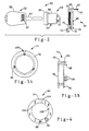
- Figure 2 shows a blown-apart side view of a key assembly 50 including an ignition key 52, a steering lock assembly 54 and a bobbin assembly 56.
- the ignition key 52 includes a head portion 58 and a key portion 60.
- the head portion 58 of the key 52 encapsulates the components of the unit 12 as discussed above with reference to Figure 1.
- the coil L 1 is shown as a coil 62 at the base of the head portion 58 proximate to the key portion 60 to show how it is aligned to be inductively coupled with the coil L 2 .
- the steering lock assembly 54 includes an outer housing 64 having a non-metallic insulating cover ring portion 66 at one end that is in close proximity to the head portion 58 when the ignition key 52 is inserted within the steering lock assembly 54.
- the steering lock assembly 54 further includes a cylindrical portion 68 extending from the ring portion 66.
- a series of protrusions 70 at an end of the cylindrical portion 68 opposite to the ring portion 66 are provided to secure the steering lock assembly 54 to a vehicle structure (not shown) as is well understood in the art.
- the steering lock assembly 54 is a conventional steering lock assembly in the art. When the ignition key 52 is inserted into the steering lock assembly 54, the ignition key 52 engages an ignition switch (not shown) within the housing 64 so as to cause the vehicle to start when the ignition key 52 is rotated in the conventional manner.
- the bobbin assembly 56 is configured as a ring assembly such that the bobbin assembly 56 is slidably engageable onto the cylindrical portion 68 of the steering lock assembly 54.
- the bobbin assembly 56 includes a bobbin 74 formed of molded plastic having a front plate 76 and a back plate 78 separating a cylindrical portion 80 (see Figure 3(b)).
- the inductor L 2 is shown here as a coil 82 wound on the cylindrical portion 80 of the bobbin 74.
- a printed circuit board 84 is mounted to the back plate 78 of the bobbin 74 such that surface mounted components 86 extend from the board 84 opposite to the plate 78.
- the components 86 represent the electrical circuit components that make up the oscillator circuit 44, and are shown here as components merely for diagrammatic purposes.
- a two-pin connector 88 is connected to the printed circuit board 84.
- a DC signal wire 90 and a ground wire 92 are electrically connected to the 2-pin connector 88 in order to provide the power to energize the oscillator circuit 44.
- the signal wire 90 is connected to the microprocessor 34 to operate the oscillator circuit 44 as discussed above.
- An output of the oscillator circuit 44 is connected to the coil 82 at a pin connection 94.
- the bobbin assembly 56 is slidably engageable onto the cylindrical portion 68 such that the front plate 76 rides flush against a back surface of the ring portion 66. Therefore, when the ignition key 52 is inserted within the steering lock assembly 54, the coil 62 is positioned adjacent to the coil 82, but is separated by free space and the insulative ring portion 66. Magnetic field lines generated by the coil 82 are transmitted through the ring portion 66 in order to energize the coil 62.
- Figures 3(a) and 3(b) show a front view and a side view, respectively, of the bobbin 74.
- a series of spring tab projections 98 that include hooked ends are provided for securing the printed circuit board 84 to the bobbin 74 so that the surface mounted components extend from the back plate 78 of the bobbin 74.
- the cylindrical portion 80 is shown without the coil 82 wound thereon. In one example, the coil 82 is wound on the cylindrical portion 80 with 20 turns of no. 28 AWG wire.
- Two terminal pins 100 are shown where the terminal connector 88 is connected thereto.
- Figure 4 shows a front view of the printed circuit board 84.
- the components 86 are surface mounted on a front surface of the printed circuit board 84.
- a series of three slots 102 accept the spring tab projections 98 such that the hooked ends engage a surface of the printed circuit board 84 in order to secure the printed circuit board 84 to the bobbin 74 to form the bobbin assembly 56.
- a slot 104 engages a tab (not shown) on the cylindrical portion 68 so as to prevent the bobbin assembly 56 from rotating on the steering lock assembly 54.
Landscapes
- Engineering & Computer Science (AREA)
- Mechanical Engineering (AREA)
- Computer Networks & Wireless Communication (AREA)
- Physics & Mathematics (AREA)
- General Physics & Mathematics (AREA)
- Lock And Its Accessories (AREA)
Claims (19)
- Système de sécurité pour la protection de caravanes de véhicules (10) afin d'empêcher une personne non autorisée d'activer un véhicule, ledit système comprenant une unité de transpondeur comprenant un premier microprocesseur (14), un premier circuit oscillant, une première bobine (21) et une pile (16) et une unité d'ensemble de braquage de la direction comprenant un second circuit oscillant et une seconde bobine sur un ensemble d'enroulements, le système étant caractérisé par :un émetteur FOB pour transmettre les signaux codés afin d'empêcher l'activation non autorisée et pour permettre la commande à distance de la fonction du véhicule ayant un signal d'activation ;ledit émetteur FOB comprenant :un premier microprocesseur (14)pour générer un premier signal codé pour commander à distance une fonction à l'intérieur du véhicule ; etpour générer un second signal codé, pour sécuriser le véhicule, en réponse à la réception d'un signal électrique ;une première bobine (L1) pour recevoir ledit signal électrique ;un premier circuit (20) pour transmettre lesdits premier et second signaux codés ;un récepteur (28, 30) pour recevoir lesdits signaux codés afin d'empêcher l'activation non autorisée du véhicule, et pour déclencher la commande à distance d'une fonction du véhicule, ledit récepteur comprenant :un second circuit (32) pour recevoir lesdits premier et second signaux codés ;une seconde bobine (L2) devant se coupler à ladite première bobine afin de transmettre ledit signal électrique à ladite première bobine en réponse à la réception du signal d'activation ; etun second microprocesseur (34)pour déterminer la validité dudit premier signal codé reçu et pour lancer la fonction à distance étant activée à l'intérieur du véhicule si ledit premier signal codé reçu est correct ; etpour déterminer la validité dudit second signal codé reçu, et pour sécuriser le véhicule en générant un signal d'activation si ledit second signal codé reçu est correct.
- Système selon la revendication 1, dans lequel ledit signal électrique comprend un troisième signal codé, ledit premier microprocesseur (14) recevant ledit troisième signal codé, pour comparer ledit troisième signal codé à un code stocké, et pour générer ledit second signal codé si ledit troisième signal codé est correct.
- Système selon la revendication 2, dans lequel ledit émetteur FOB comprend en outre :une première impédance pour recevoir ledit signal électrique ayant une constante de temps relativement longue de manière à émettre un signal électrique substantiellement constant audit premier microprocesseur (14) ; etune seconde impédance pour recevoir ledit signal électrique ayant une constante de temps relativement courte de manière à autoriser ledit premier microprocesseur à décoder ledit second signal codé.
- Système selon la revendication 1, dans lequel ledit premier microprocesseur (14) est alimenté par ledit signal électrique aux fins de génération et de transmission dudit second signal codé si lesdites première (L1) et seconde (L2) bobines sont couplées l'une à l'autre.
- Système selon la revendication 1, dans lequel ladite première bobine (L1), ledit premier microprocesseur (14) et ledit premier circuit (20) dudit émetteur FOB sont configurés à l'intérieur d'une clé d'allumage (52) associée au véhicule.
- Système selon la revendication 1, dans lequel ladite seconde bobine (L2) et ledit second circuit (32) sont configurés sur un ensemble d'enroulements (56) positionné autour d'un ensemble de braquage de la direction (42) associé au véhicule.
- Système selon la revendication 6, dans lequel :ladite première bobine (L1), ledit microprocesseur (14) et ledit premier circuit (20) dudit émetteur FOB sont configurés à l'intérieur d'une clé d'allumage (52) associée au véhicule ;ladite seconde bobine (L2) et ledit second circuit (32) sont configurés sur un ensemble d'enroulements (56) positionné autour d'un ensemble de braquage de la direction (42) associé au véhicule : etladite seconde bobine (L2) est enroulée sur un enroulement (74) associé audit ensemble d'enroulements (56) et des composants électriques associés audit premier circuit (20) sont montés sur un plateau (78) dudit enroulement de sorte que lorsque ladite clé d'allumage est insérée dans un ensemble de clés d'allumage (50), lesdites première et seconde bobines sont à proximité étroite l'une de l'autre et sont séparées par une bague isolante (66) associée audit ensemble de braquage de la direction.
- Système selon la revendication 1, dans lequel :ladite première bobine (L1), ledit premier microprocesseur (14) et ledit premier circuit (20) dudit émetteur FOB sont configurés à l'intérieur d'une unité de transpondeur distante ;ladite unité de transpondeur distante comprend un commutateur de fonctions (S1, S2) pour activer une fonction particulière du véhicule, ledit premier signal codé comprend un signal codé de fonction, et ledit second microprocesseur (34) lance ladite fonction particulière du véhicule après avoir déterminé si ledit premier signal codé et ledit signal codé de fonction sont corrects.
- Système selon la revendication 1 comprenant :un transpondeur FOB distant pour transmettre les signaux codés afin de commander à distance la fonction du véhicule, et pour transmettre les signaux codés afin d'empêcher l'activation non autorisée ;ledit transpondeur FOB distant comprenant :une première bobine (L1) pour recevoir un signal électrique, ledit signal électrique comprenant un signal codé ID ;un premier microprocesseur (14)pour générer un premier signal codé pour commander à distance la fonction du véhicule ; etpour déterminer la validité dudit signal codé ID, et pour générer un second signal codé, en réponse audit signal codé ID étant correct, pour sécuriser le véhicule et assurer la protection des caravanes de véhicules ;un commutateur de fonctions (S1, S2) pour commander audit premier microprocesseur de combiner un signal codé de fonction du véhicule reflétant la fonction du véhicule devant être activée à distance par ledit premier signal codé ;un premier circuit oscillant (20) pour imposer lesdits premier et second signaux codés sur une fréquence porteuse, et pour transmettre lesdits premier et second signaux codés ;un émetteur-récepteur pour recevoir les signaux codés afin d'empêcher l'activation non autorisée du véhicule, et pour déclencher la commande d'une fonction du véhicule, ledit émetteur-récepteur comprenant :un second circuit oscillant (32) pour recevoir lesdits premier et second signaux codés, et pour retirer ladite fréquence porteuse desdits premier et second signaux codés ;une seconde bobine (L2) devant se coupler à ladite première bobine afin de transmettre ledit signal électrique à ladite première bobine en réponse à la réception du signal d'activation ;un second microprocesseur (34)pour comparer ledit premier signal codé reçu à un premier code stocké afin de déterminer la validité dudit premier signal codé reçu, et pour lancer à distance la fonction étant commandée à l'intérieur du véhicule si ledit premier signal codé reçu est correct ; etpour générer ledit signal codé ID avec ledit signal électrique, pour comparer ledit premier signal codé reçu à un second code stocké pour déterminer la validité dudit second signal codé, et pour générer un signal d'allumage afin de sécuriser le véhicule si ledit second signal codé est correct.
- Système selon la revendication 9, dans lequel ledit premier microprocesseur (14) est alimenté par ledit signal électrique aux fins de génération et de transmission dudit second signal codé si lesdites première (L1) et seconde (L2) bobines sont couplées l'une à l'autre.
- Système selon la revendication 10, dans lequel ledit transpondeur FOB distant comprend en outre :une première impédance pour recevoir ledit signal électrique ayant une constante de temps relativement longue de manière à émettre un signal électrique substantiellement constant audit premier microprocesseur ; etune seconde impédance pour recevoir ledit signal électrique ayant une constante de temps relativement courte de manière à autoriser ledit premier microprocesseur à décoder ledit second signal codé.
- Système selon la revendication 9, dans lequel :ladite première bobine (L1), ledit premier microprocesseur (14), et ledit premier circuit (20) dudit émetteur FOB sont configurés à l'intérieur d'une clé d'allumage (52) associée au véhicule ;ladite seconde bobine (L2) et ledit second circuit (32) sont configurés sur un ensemble d'enroulements (56) positionné autour d'un ensemble de braquage de la direction (42) associé au véhicule ; etladite seconde bobine est enroulée sur un enroulement (74) associé audit ensemble d'enroulements et des composants électriques associés audit premier circuit sont montés sur un plateau (78) dudit enroulement de sorte que lorsque ladite clé d'allumage (52) est insérée dans un ensemble de clés d'allumage, lesdites première et seconde bobines sont à proximité étroite l'une de l'autre et sont séparées par une bague isolante (66) associée audit ensemble de braquage de la direction.
- Système selon la revendication 9, dans lequel ledit transpondeur FOB distant comprend une pluralité de commutateurs de fonctions (S1, S2), chaque commutateur de fonctions de ladite pluralité autorisant ledit premier microprocesseur (14) à transmettre un code de bits de données de fonction différent à l'intérieur dudit premier signal codé afin d'autoriser ledit second microprocesseur (34) à exécuter les fonctions du véhicule.
- Système selon la revendication 9, dans lequel :ladite première bobine (L1), ledit premier microprocesseur (14) et ledit premier circuit (20) dudit émetteur FOB sont configurés à l'intérieur d'une unité de transpondeur distante ; etladite unité de transpondèur distante comprend un commutateur de fonctions pour activer une fonction particulière du véhicule, ledit premier signal codé comprend un signal codé de fonction, et ledit second microprocesseur (34) lance ladite fonction particulière du véhicule après avoir déterminé si ledit premier signal codé et ledit signal codé de fonction sont corrects.
- Système selon la revendication 1 comprenant :un transpondeur FOB distant à clé d'allumage pour transmettre les signaux codés afin de commander à distance une fonction du véhicule, et pour transmettre les signaux codés afin d'empêcher l'activation non autorisée du véhicule, ledit transpondeur FOB distant à clé d'allumage comprenant :une première bobine (L1) pour recevoir un signal électrique, ledit signal électrique comprenant un signal ID ;un premier microprocesseur (14)pour générer un premier signal codé pour commander à distance la fonction du véhicule ; etpour déterminer la validité dudit signal codé ID, et pour générer un second signal codé, en réponse audit signal codé ID étant correct, pour sécuriser le véhicule et assurer la protection des caravanes de véhicules ;un commutateur de fonctions distant pour commander audit premier microprocesseur de combiner un signal codé de fonction du véhicule reflétant la fonction du véhicule devant être activée à distance par ledit premier signal codé ; etun premier circuit oscillant (20) pour imposer lesdits premier et second signaux codés sur une fréquence porteuse, et pour transmettre lesdits premier et second signaux codés ; etun émetteur-récepteur d'ensemble d'allumage pour recevoir les signaux codés afin d'empêcher l'activation non autorisée du véhicule et pour déclencher la commande de la fonction du véhicule, ledit émetteur-récepteur comprenant :un ensemble d'enroulements (56) comprenant :un second circuit oscillant (32) pour recevoir lesdits premier et second signaux codés, et pour retirer ladite fréquence porteuse desdits premier et second signaux codés ; etune seconde bobine (L2) enroulée autour d'un enroulement (74) devant se coupler à ladite première bobine afin de transmettre ledit signal électrique à ladite première bobine en réponse à la réception du signal d'activation ; etun second microprocesseur (34)pour comparer ledit premier signal codé reçu à un premier code stocké afin de déterminer la validité dudit premier signal codé reçu, et pour lancer à distance la fonction étant commandée à l'intérieur du véhicule si ledit premier signal codé reçu est correct ; etpour générer ledit signal codé ID avec ledit signal électrique, pour comparer ledit premier signal codé reçu à un second code stocké pour déterminer la validité dudit second signal codé et pour générer un signal d'allumage si ledit second signal codé est correct ; etun système de commutateurs d'allumage ayant ledit ensemble d'enroulements (56) positionné de part et d'autre pour recevoir ledit signal d'allumage afin de sécuriser le véhicule.
- Système selon la revendication 15, dans lequel ledit premier microprocesseur (14) est alimenté par ledit signal électrique aux fins de génération et de transmission dudit second signal codé si lesdites première (L1) et seconde (L2) bobines sont couplées l'une à l'autre.
- Système selon la revendication 15, dans lequel ledit transpondeur FOB distant à clé d'allumage comprend en outre :une première impédance pour recevoir ledit signal électrique ayant une constante de temps relativement longue de manière à émettre un signal électrique substantiellement constant audit premier microprocesseur ; etune seconde impédance pour recevoir ledit signal électrique ayant une constante de temps relativement courte de manière à autoriser ledit premier microprocesseur à décoder ledit second signal codé.
- Système selon la revendication 15, dans lequel ledit transpondeur FOB distant à clé d'allumage comprend une pluralité de commutateurs de fonctions (S1, S2), chaque commutateur de fonctions de ladite pluralité autorisant le premier microprocesseur (14) à transmettre un code de bits de données de fonction différent à l'intérieur dudit premier signal codé afin d'autoriser ledit second microprocesseur (34) à exécuter les fonctions du véhicule.
- Système selon la revendication 15, dans lequel ladite unité de transpondeur distante comprend un commutateur de fonctions (S1, S2) pour activer une fonction particulière du véhicule, ledit premier signal codé comprend un signal codé de fonction, et ledit second microprocesseur (34) lance ladite fonction particulière du véhicule après avoir déterminé si ledit premier signal codé et ledit signal codé de fonction sont corrects.
Applications Claiming Priority (3)
| Application Number | Priority Date | Filing Date | Title |
|---|---|---|---|
| US360644 | 1989-06-02 | ||
| US36064494A | 1994-12-21 | 1994-12-21 | |
| PCT/US1995/016088 WO1996019629A1 (fr) | 1994-12-21 | 1995-12-13 | Systeme radiofrequence de commande a distance associe a un systeme antivol |
Publications (2)
| Publication Number | Publication Date |
|---|---|
| EP0799358A1 EP0799358A1 (fr) | 1997-10-08 |
| EP0799358B1 true EP0799358B1 (fr) | 2002-03-27 |
Family
ID=23418871
Family Applications (1)
| Application Number | Title | Priority Date | Filing Date |
|---|---|---|---|
| EP95943750A Expired - Lifetime EP0799358B1 (fr) | 1994-12-21 | 1995-12-13 | Systeme radiofrequence de commande a distance associe a un systeme antivol |
Country Status (5)
| Country | Link |
|---|---|
| US (1) | US5724028A (fr) |
| EP (1) | EP0799358B1 (fr) |
| JP (1) | JPH10511441A (fr) |
| DE (1) | DE69526116T2 (fr) |
| WO (1) | WO1996019629A1 (fr) |
Families Citing this family (46)
| Publication number | Priority date | Publication date | Assignee | Title |
|---|---|---|---|---|
| BR9609543A (pt) * | 1995-07-24 | 1999-02-23 | Siemens Ag | Sistema de proteção contra furto para um veículo automotivo |
| JPH09100666A (ja) * | 1995-10-05 | 1997-04-15 | Tokai Rika Co Ltd | キーシリンダ |
| DE19622720C2 (de) * | 1996-06-06 | 1999-07-15 | Megamos F & G Sicherheit | Authentifizierungseinrichtung mit Schlüsselzahlspeicher |
| EP0848123B1 (fr) * | 1996-10-10 | 2004-12-08 | Texas Instruments Deutschland Gmbh | Système télécommandé d'entrée sans clé |
| FR2755925B1 (fr) * | 1996-11-20 | 1999-01-29 | Texton | Equipement de vehicule automobile comprenant un dispositif antivol et un dispositif a telecommande |
| US5889603A (en) * | 1996-12-04 | 1999-03-30 | Ut Automotive Dearborn, Inc. | Optical drive away prevention security system |
| JP3256666B2 (ja) * | 1996-12-25 | 2002-02-12 | 三菱電機株式会社 | 車両用リモコン装置および車両セキュリティ装置 |
| FR2759960B1 (fr) * | 1997-02-27 | 1999-04-23 | Texton | Dispositif de protection de vehicule automobile contre le vol et transpondeur pour un tel dispositif |
| JP3427694B2 (ja) * | 1997-09-19 | 2003-07-22 | 日産自動車株式会社 | 車両用セキュリティ装置 |
| DE19747654A1 (de) * | 1997-10-29 | 1999-05-20 | Telefunken Microelectron | Verfahren zum Betreiben eines Sicherungssystems |
| US6442986B1 (en) | 1998-04-07 | 2002-09-03 | Best Lock Corporation | Electronic token and lock core |
| US8538801B2 (en) | 1999-02-19 | 2013-09-17 | Exxonmobile Research & Engineering Company | System and method for processing financial transactions |
| US7571139B1 (en) | 1999-02-19 | 2009-08-04 | Giordano Joseph A | System and method for processing financial transactions |
| US6181025B1 (en) * | 1999-05-21 | 2001-01-30 | Lear Corporation | Integral interrogator-coil circuit |
| US6400040B1 (en) | 2000-03-03 | 2002-06-04 | Lear Corporation | Vehicle ignition and remote keyless entry assembly |
| US6494705B1 (en) * | 2000-05-18 | 2002-12-17 | Stephen Feilinger | Apparatus for rotational mold with movable insert |
| US6420967B1 (en) | 2001-01-31 | 2002-07-16 | Lear Corporation | System and method for shared vehicle tire pressure monitoring, remote keyless entry, and vehicle immobilization |
| US6864803B2 (en) | 2001-10-12 | 2005-03-08 | Lear Corporation | System and method for tire pressure monitoring using CDMA tire pressure signals |
| US6693522B2 (en) | 2001-10-12 | 2004-02-17 | Lear Corporation | System and method for tire pressure monitoring including automatic tire location recognition |
| US6505780B1 (en) | 2001-12-05 | 2003-01-14 | Koninklijke Philips Electronics N.V. | Personalize vehicle settings using RF tags |
| US6691567B2 (en) | 2002-03-01 | 2004-02-17 | Lear Corporation | System and method for tire pressure monitoring including automatic tire location recognition |
| US6668636B2 (en) | 2002-03-01 | 2003-12-30 | Lear Corporation | System and method for tire pressure monitoring including tire location recognition |
| US6829924B2 (en) * | 2002-03-01 | 2004-12-14 | Lear Corporation | Tire pressure monitoring system with low frequency initiation approach |
| US6876265B2 (en) | 2002-03-01 | 2005-04-05 | Lear Corporation | System and method for using a saw based RF transmitter for AM modulated transmission in a TPM |
| US7154414B2 (en) * | 2002-03-01 | 2006-12-26 | Lear Corporation | System and method for remote tire pressure monitoring |
| US6788193B2 (en) | 2002-03-01 | 2004-09-07 | Lear Corporation | System and method for tire pressure monitoring providing automatic tire location recognition |
| US6933898B2 (en) * | 2002-03-01 | 2005-08-23 | Lear Corporation | Antenna for tire pressure monitoring wheel electronic device |
| US20030164759A1 (en) * | 2002-03-01 | 2003-09-04 | Lear Corporation | System and method for tire pressure monitoring with optimal tire pressure indication during tire pressure adjustment |
| US20030164760A1 (en) * | 2002-03-01 | 2003-09-04 | Lear Corporation | System and method for tire pressure monitoring using vehicle radio |
| US6725712B1 (en) | 2002-03-01 | 2004-04-27 | Lear Corporation | System and method for tire pressure monitoring with automatic tire location recognition |
| US6647773B2 (en) | 2002-03-01 | 2003-11-18 | Lear Corporation | System and method for integrated tire pressure monitoring and passive entry |
| US6838985B2 (en) * | 2002-03-25 | 2005-01-04 | Lear Corporation | System and method for remote tire pressure monitoring with low frequency initiation |
| US20030179086A1 (en) * | 2002-03-25 | 2003-09-25 | Lear Corporation | System for remote tire pressure monitoring with low frequency initiation antenna |
| US6633155B1 (en) * | 2002-05-06 | 2003-10-14 | Hui-Pin Liang | Wireless mouse induction power supply |
| US6873247B2 (en) * | 2002-10-25 | 2005-03-29 | Lear Corporation | Combined vehicle immobilizing and steering column control system |
| US7119667B2 (en) * | 2004-06-28 | 2006-10-10 | Delphi Technologies, Inc. | Integrated electronic security system for vehicle |
| JP4696757B2 (ja) * | 2005-07-28 | 2011-06-08 | アイシン精機株式会社 | ドアロック制御装置 |
| US7557763B2 (en) * | 2005-10-18 | 2009-07-07 | Continental Automotive Systems Us, Inc. | Housing mounted Z-axis antenna coil |
| US8350670B2 (en) * | 2007-07-12 | 2013-01-08 | Kelly Michael P | Methods and systems for secure keyless entry for vehicle fleet management |
| US20090243796A1 (en) * | 2008-03-28 | 2009-10-01 | Tieman Craig A | Adaptive power keyless fob |
| US9742555B2 (en) * | 2008-09-25 | 2017-08-22 | Nokia Technologies Oy | Encryption/identification using array of resonators at transmitter and receiver |
| US8325039B2 (en) * | 2010-02-25 | 2012-12-04 | Sargent Manufacturing Company | Locking device with embedded circuit board |
| US9443071B2 (en) * | 2010-06-18 | 2016-09-13 | At&T Intellectual Property I, L.P. | Proximity based device security |
| US9210188B2 (en) | 2012-04-17 | 2015-12-08 | Dae Dong Co., Ltd. | Method for preventing relay-attack on smart key system |
| US20160291854A1 (en) * | 2015-03-30 | 2016-10-06 | Ford Motor Company Of Australia Limited | Methods and systems for configuration of a vehicle feature |
| CN107939173B (zh) * | 2017-12-29 | 2023-05-23 | 青岛海信电子设备股份有限公司 | 一种信标装置防拆结构 |
Family Cites Families (22)
| Publication number | Priority date | Publication date | Assignee | Title |
|---|---|---|---|---|
| DE2253859A1 (de) * | 1972-11-03 | 1974-05-09 | Telefunken Fernseh & Rundfunk | System zur fernbedienung eines elektrischen geraetes |
| DE3244049C2 (de) * | 1982-11-27 | 1986-06-26 | Kiekert GmbH & Co KG, 5628 Heiligenhaus | Zentralverriegelungsanlage für ein Kraftfahrzeug |
| DE3529882A1 (de) * | 1985-08-21 | 1987-02-26 | Vdo Schindling | System zum ver- und / oder entriegeln einer sicherheitseinrichtung |
| DE3636822C2 (de) * | 1986-10-29 | 1993-12-23 | Ruf Kg Wilhelm | Elektronische Fernbetätigungseinrichtung, insbesondere für Zentralverriegelungsanlagen von Kraftfahrzeugen |
| US5109221A (en) * | 1987-05-21 | 1992-04-28 | Trw Inc. | Remote control system for door locks |
| NL8702749A (nl) * | 1987-11-18 | 1989-06-16 | Philips Nv | Afstandsbedieningssysteem met ontwaak signaal. |
| DE3806469A1 (de) * | 1988-03-01 | 1989-09-14 | Bks Gmbh | Vorrichtung zur elektrischen energieversorgung von tuerschloessern |
| US4942393A (en) * | 1988-05-27 | 1990-07-17 | Lectron Products, Inc. | Passive keyless entry system |
| IT1223678B (it) * | 1988-07-11 | 1990-09-29 | Mario Turatti | Sistema identificatore elettronico particolarmente per il comando di bloccasterzo serrature di portiere ed altre applicazioni automobilistiche |
| KR940000297B1 (ko) * | 1988-07-13 | 1994-01-14 | 마쯔시다덴기산교 가부시기가이샤 | 통신기기 |
| US5467082A (en) * | 1989-10-25 | 1995-11-14 | Sanderson; Glenn A. | Proximity actuator and reader for an electronic access system |
| US5144667A (en) * | 1990-12-20 | 1992-09-01 | Delco Electronics Corporation | Method of secure remote access |
| US5105162A (en) * | 1991-06-20 | 1992-04-14 | United Technologies Automotive | Electrically tuned RF receiver, apparatus and method therefor |
| IT1253068B (it) * | 1991-07-01 | 1995-07-10 | Medardo Reggiani | Antifurto ad inserimento passivo |
| US5191610A (en) * | 1992-02-28 | 1993-03-02 | United Technologies Automotive, Inc. | Remote operating system having secure communication of encoded messages and automatic re-synchronization |
| US5442341A (en) * | 1992-04-10 | 1995-08-15 | Trw Inc. | Remote control security system |
| US5287112A (en) * | 1993-04-14 | 1994-02-15 | Texas Instruments Incorporated | High speed read/write AVI system |
| DE4317119C2 (de) * | 1993-05-21 | 1996-04-04 | Audi Ag | Diebstahlschutzeinrichtung als Immobilisationseinrichtung an einem Kraftfahrzeug |
| DE4323530A1 (de) * | 1993-07-14 | 1995-01-19 | Philips Patentverwaltung | Datenaustauschanordnung |
| JP2823491B2 (ja) * | 1993-08-30 | 1998-11-11 | 株式会社東海理化電機製作所 | 車両用盗難防止装置 |
| DE9320270U1 (de) * | 1993-10-01 | 1994-05-05 | Marquardt Gmbh, 78604 Rietheim-Weilheim | Schließmanagement |
| US5461386A (en) * | 1994-02-08 | 1995-10-24 | Texas Instruments Incorporated | Inductor/antenna for a recognition system |
-
1995
- 1995-12-13 JP JP8519860A patent/JPH10511441A/ja active Pending
- 1995-12-13 DE DE69526116T patent/DE69526116T2/de not_active Expired - Lifetime
- 1995-12-13 WO PCT/US1995/016088 patent/WO1996019629A1/fr not_active Ceased
- 1995-12-13 EP EP95943750A patent/EP0799358B1/fr not_active Expired - Lifetime
-
1997
- 1997-06-03 US US08/868,327 patent/US5724028A/en not_active Expired - Lifetime
Also Published As
| Publication number | Publication date |
|---|---|
| US5724028A (en) | 1998-03-03 |
| DE69526116D1 (de) | 2002-05-02 |
| DE69526116T2 (de) | 2002-11-21 |
| EP0799358A1 (fr) | 1997-10-08 |
| WO1996019629A1 (fr) | 1996-06-27 |
| JPH10511441A (ja) | 1998-11-04 |
Similar Documents
| Publication | Publication Date | Title |
|---|---|---|
| US5724028A (en) | RF remote system with drive-away prevention | |
| US6351206B1 (en) | Antitheft protection system for a motor vehicle | |
| US6011320A (en) | Vehicle anti-theft device using both electromagnetic induction and frequency modulation transmission of power and data | |
| US6965295B2 (en) | Electronic key system operable with charge capacitor power | |
| US4973958A (en) | Keyless entry system for automotive devices antenna device allowing low power radio signal communication | |
| EP0848123B1 (fr) | Système télécommandé d'entrée sans clé | |
| EP0767286A2 (fr) | Système télécommandé d'entrée sans clé et d'immobilisation pour véhicules automobiles | |
| EP0892134B1 (fr) | Dispositif de verrouillage pour vehicules | |
| JPH08193444A (ja) | 遠隔操作装置並びにトランスポンダを有する自動車用施錠装置 | |
| GB2290342A (en) | A tumberless ignition lock having an antenna | |
| AU2014270647A1 (en) | Immobiliser system with controllable inhibiting means | |
| US20040257296A1 (en) | Door handle for a vehicle | |
| EP0885787B1 (fr) | Système de clef pour véhicules | |
| Davis et al. | Combined remote key control and immobilization system for vehicle security | |
| GB2309046A (en) | Method of operation of authentication system | |
| EP1454302B1 (fr) | Systeme de protection accessoire contre l'utilisation non autorisee d'une cle d'acces et/ou de contact | |
| US7551066B1 (en) | Method and system for transmitting data for a security system of a motor vehicle | |
| GB2296804A (en) | Electronic security system | |
| JP4923626B2 (ja) | 車両用無線通信システム及び無線通信方法 | |
| GB2372534A (en) | Transponder key with rechargeable internal battery | |
| JPH09105255A (ja) | 車両コントロールシステム | |
| JP3507153B2 (ja) | 車両用ドアロック制御装置 | |
| US6121891A (en) | Passive proximity transceiver having an improved casing | |
| JP3667878B2 (ja) | 車両用負荷制御装置 | |
| JP3433993B2 (ja) | 自動車用駆動制御装置 |
Legal Events
| Date | Code | Title | Description |
|---|---|---|---|
| PUAI | Public reference made under article 153(3) epc to a published international application that has entered the european phase |
Free format text: ORIGINAL CODE: 0009012 |
|
| 17P | Request for examination filed |
Effective date: 19970530 |
|
| AK | Designated contracting states |
Kind code of ref document: A1 Designated state(s): DE ES FR GB IT SE |
|
| RAP1 | Party data changed (applicant data changed or rights of an application transferred) |
Owner name: UT AUTOMOTIVE DEARBORN, INC. |
|
| RAP1 | Party data changed (applicant data changed or rights of an application transferred) |
Owner name: LEAR AUTOMOTIVE DEARBORN, INC. |
|
| 17Q | First examination report despatched |
Effective date: 20000208 |
|
| GRAG | Despatch of communication of intention to grant |
Free format text: ORIGINAL CODE: EPIDOS AGRA |
|
| GRAG | Despatch of communication of intention to grant |
Free format text: ORIGINAL CODE: EPIDOS AGRA |
|
| GRAG | Despatch of communication of intention to grant |
Free format text: ORIGINAL CODE: EPIDOS AGRA |
|
| GRAH | Despatch of communication of intention to grant a patent |
Free format text: ORIGINAL CODE: EPIDOS IGRA |
|
| GRAH | Despatch of communication of intention to grant a patent |
Free format text: ORIGINAL CODE: EPIDOS IGRA |
|
| REG | Reference to a national code |
Ref country code: GB Ref legal event code: IF02 |
|
| GRAA | (expected) grant |
Free format text: ORIGINAL CODE: 0009210 |
|
| AK | Designated contracting states |
Kind code of ref document: B1 Designated state(s): DE ES FR GB IT SE |
|
| PG25 | Lapsed in a contracting state [announced via postgrant information from national office to epo] |
Ref country code: IT Free format text: LAPSE BECAUSE OF FAILURE TO SUBMIT A TRANSLATION OF THE DESCRIPTION OR TO PAY THE FEE WITHIN THE PRESCRIBED TIME-LIMIT;WARNING: LAPSES OF ITALIAN PATENTS WITH EFFECTIVE DATE BEFORE 2007 MAY HAVE OCCURRED AT ANY TIME BEFORE 2007. THE CORRECT EFFECTIVE DATE MAY BE DIFFERENT FROM THE ONE RECORDED. Effective date: 20020327 Ref country code: FR Free format text: LAPSE BECAUSE OF FAILURE TO SUBMIT A TRANSLATION OF THE DESCRIPTION OR TO PAY THE FEE WITHIN THE PRESCRIBED TIME-LIMIT Effective date: 20020327 |
|
| REF | Corresponds to: |
Ref document number: 69526116 Country of ref document: DE Date of ref document: 20020502 |
|
| PG25 | Lapsed in a contracting state [announced via postgrant information from national office to epo] |
Ref country code: SE Free format text: LAPSE BECAUSE OF FAILURE TO SUBMIT A TRANSLATION OF THE DESCRIPTION OR TO PAY THE FEE WITHIN THE PRESCRIBED TIME-LIMIT Effective date: 20020627 |
|
| PG25 | Lapsed in a contracting state [announced via postgrant information from national office to epo] |
Ref country code: ES Free format text: LAPSE BECAUSE OF FAILURE TO SUBMIT A TRANSLATION OF THE DESCRIPTION OR TO PAY THE FEE WITHIN THE PRESCRIBED TIME-LIMIT Effective date: 20020925 |
|
| EN | Fr: translation not filed | ||
| PLBE | No opposition filed within time limit |
Free format text: ORIGINAL CODE: 0009261 |
|
| STAA | Information on the status of an ep patent application or granted ep patent |
Free format text: STATUS: NO OPPOSITION FILED WITHIN TIME LIMIT |
|
| 26N | No opposition filed |
Effective date: 20021230 |
|
| PGFP | Annual fee paid to national office [announced via postgrant information from national office to epo] |
Ref country code: GB Payment date: 20131227 Year of fee payment: 19 Ref country code: DE Payment date: 20131230 Year of fee payment: 19 |
|
| REG | Reference to a national code |
Ref country code: DE Ref legal event code: R119 Ref document number: 69526116 Country of ref document: DE |
|
| GBPC | Gb: european patent ceased through non-payment of renewal fee |
Effective date: 20141213 |
|
| PG25 | Lapsed in a contracting state [announced via postgrant information from national office to epo] |
Ref country code: DE Free format text: LAPSE BECAUSE OF NON-PAYMENT OF DUE FEES Effective date: 20150701 Ref country code: GB Free format text: LAPSE BECAUSE OF NON-PAYMENT OF DUE FEES Effective date: 20141213 |