EP0799761B1 - Structure de fourche avant pour bicyclette - Google Patents
Structure de fourche avant pour bicyclette Download PDFInfo
- Publication number
- EP0799761B1 EP0799761B1 EP97100934A EP97100934A EP0799761B1 EP 0799761 B1 EP0799761 B1 EP 0799761B1 EP 97100934 A EP97100934 A EP 97100934A EP 97100934 A EP97100934 A EP 97100934A EP 0799761 B1 EP0799761 B1 EP 0799761B1
- Authority
- EP
- European Patent Office
- Prior art keywords
- sliding
- cylindrical
- pipes
- crown portion
- spring means
- Prior art date
- Legal status (The legal status is an assumption and is not a legal conclusion. Google has not performed a legal analysis and makes no representation as to the accuracy of the status listed.)
- Expired - Lifetime
Links
Images


Classifications
-
- B—PERFORMING OPERATIONS; TRANSPORTING
- B62—LAND VEHICLES FOR TRAVELLING OTHERWISE THAN ON RAILS
- B62K—CYCLES; CYCLE FRAMES; CYCLE STEERING DEVICES; RIDER-OPERATED TERMINAL CONTROLS SPECIALLY ADAPTED FOR CYCLES; CYCLE AXLE SUSPENSIONS; CYCLE SIDECARS, FORECARS, OR THE LIKE
- B62K25/00—Axle suspensions
- B62K25/04—Axle suspensions for mounting axles resiliently on cycle frame or fork
- B62K25/06—Axle suspensions for mounting axles resiliently on cycle frame or fork with telescopic fork, e.g. including auxiliary rocking arms
- B62K25/08—Axle suspensions for mounting axles resiliently on cycle frame or fork with telescopic fork, e.g. including auxiliary rocking arms for front wheel
Definitions
- the present invention relates to a structure of a bicycle front fork, and more particularly to a bicycle front fork in which a buffering mechanism is built.
- a buffering mechanism in the front fork as means for improving the riding comfort on a bicycle.
- a pair of expandable fork blade portions are provided, in which a pair of supporting pipes extending downwardly from a crown portion of the front fork are respectively fitted in a telescopic configuration with the corresponding sliding pipes, provided at their lower ends with bearing portions to support the front wheel.
- an elastic member is disposed which receives a compressive force from the compression of the two pipes fitted together in a telescopic configuration.
- the elastic members are disposed in the sliding pipes having the bearings for the front wheel, and in some cases, for reasons of design, the sliding pipes incorporating the elastic members become smaller in diameter toward the lower ends or are often curved forward in an arch.
- each sliding pipe two stopper mechanisms are incorporated: one to prevent the elastic members from being subjected to an excessive compressive deformation and the other to prevent the sliding pipe from coming off from the supporting pipe, namely, a measure against a rebound. For this reason, mounting the buffering mechanism in the front fork is not easy and the construction related to the buffering mechanism becomes complicated.
- the NL 7407263 A shows a front fork structure for a bicycle, comprising a crown portion having attached thereto a steering tube extending upwardly, a pair of expandable fork blade portion, including a pair of supporting pipes extending downwardly from the crown portion, and a pair of sliding pipes slidably fitted over corresponding supporting pipes, said fork blade portions being provided at the lower ends with axle bearings to hold an axle of the front wheel.
- Spring means generally cylindrical in shape, are provided between a top end of each sliding pipe and a bottom end of the crown portion.
- a connection member connects the sliding pipes to make the sliding pipes move in one body.
- the GB 594 749 A discloses front forks for cycles having shock absorbing means comprising a plurality of rubber bushes arranged in superimposition on a rod which is attached at one end to one of the fork elements and is free to slide on the other of the fork elements. Metallic washers are interposed between the bushes.
- the DE 9309203 U shows a one-armed upside down fork for a cycle.
- a spring element is inserted between a supporting tube and a sliding tube, the spring is arranged inside the sliding tube.
- the object of the present invention is to provide a front fork structure of a bicycle with a buffering mechanism which is free of severe restriction on the capacity of the elastic members, relatively easy to mount, and relatively simple in construction.
- the present invention provides a front fork structure for a bicycle as claimed in the main claim.
- the cylindrical spring means for elastically supporting the sliding pipe of each expandable fork blade is arranged below the crown portion in such a manner as to surround the supporting pipe. Therefore, without inserting conventional buffering elastic member into the sliding pipes, an impact can be buffered by the cylindrical spring means. Therefore, the dimensions and the capacity enough to buffer the impact can be secured for the cylindrical spring means because they are not restricted by the design of the sliding pipes.
- the stopper mechanism provided in conjunction with the connection member moving as one body with the sliding pipes, regulates the excessive movement of the sliding pipes which causes excessive compression and expansion of the cylindrical spring means. Therefore, it is possible to certainly prevent coming off of the sliding pipe from the supporting pipe and also prevent excessive compressive deformation of the cylindrical spring means.
- An advantageous embodiment of the invention is claimed in claim 4.
- an upper and an under cover generally in a cylindrical shape, by a synthetic resin material, and fitting those covers together in a telescopic configuration, the radial expansion of the dust cover during the compressive deformation of the compression coil spring can be eliminated, for which reason the dust cover of the telescopic type is advantageous in respect of design.
- the front fork structure for a bicycle because an impact can be alleviated by the cylindrical spring means mounted on the upper portions of the sliding pipes, without being subject to restriction from the design of the sliding pipes, the dimensions and the capacity sufficient to buffer an impact can be secured for the cylindrical spring means. Furthermore, by a single stopper mechanism provided in conjunction with the connection member separate from the cylindrical spring means, it is possible to prevent coming off of the sliding pipes and excessive compressive deformation of the cylindrical spring means. Therefore, an impact can be alleviated appropriately without mounting the buffering mechanism including the spring means and the stopper mechanism in the sliding pipes, and coming off of the sliding pipes from the supporting pipes and excessive compression of the spring means can be prevented certainly only by one stopper mechanism. Thus, this bicycle front fork can buffer an impact appropriately to improve the riding comfort on a bicycle by the buffering mechanism relatively easy to mount and relatively simple in construction.
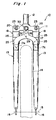
- Fig. 1 is a front view showing a principal part of a bicycle front fork according to the present invention.
- the bicycle front fork 10 according to the present invention comprises a crown portion 11, a steering tube 12 extending upwardly from the top surface of the central part of the crown portion 11, and a pair of fork blade portions 13 provided spaced a certain distance to each other and extending downwardly from the bottom faces of both sides portions of the crown portion 11.
- the steering tube 12 is held rotatably by a head tube (not shown) of a bicycle frame, not shown, and the steering tube 12 is rotated about its axis by steering the handle (not shown) mounted to the steering tube 12.
- connection member 17 is provided between the crown portion 11 and the fork blade portions 13
- cylindrical spring means 18 is mounted on each fork blade portion 13.
- Fig. 2 is a fragmentary view of the fork blade portion on an enlarged scale, partially in cross section.
- each fork blade portion 13 includes a straight supporting pipe 21 which has its top end portion inserted into a corresponding mounting hole 19 on either side of the crown portion 11 and fixed to the crown portion 11 with a locking bolt 20, and a sliding pipe 22 which contains the lower portion of the supporting pipe 21.
- the pipes 21 and 22 are fitted together in a telescopic configuration so as to be slidable along the longitudinal axis, and on that account the fork blade portion 13 can expand and contract in the longitudinal direction thereof under the crown portion 11.
- the supporting pipe 21 has a cap member 23 mounted at its top end to close the opening.
- the supporting pipe 21 has mounted on the outer circumferential surface at its lower end a cylindrical sleeve 24 of a synthetic resin material, for example, for smooth sliding motion of the sliding pipe 22 against the supporting pipe 21.
- Each spring means 18 is so arranged as to encircling the supporting pipe 21 between the crown portion 11 and the top end of the sliding pipe 22.
- the spring means 18 is a spring assembly, including a pair of cylindrical rubber members 25, an intermediate sleeve 26 to be inserted between the rubber members 25, and a pair of outer sleeves 27.
- Each of the sleeves 26 and 27 is cylindrical in shape, made of a synthetic resin material, and fitted on the supporting pipe 22.
- the flange portions 26a and 27a are used to hold the end faces of the rubber members 25.
- Those sleeves 26 and 27 may be formed of the same synthetic resin material as in the cylindrical sleeve 24.
- the spring means 18 is mounted around the supporting pipe 21 between the crown portion 11 and the sliding pipe 22 to arrange a pair of the rubber members 25 in a straight line.
- the sleeves 26 and 27 are fitted to the rubber members 25 seated on the flange portions 26a and 27a such that the intermediate sleeve 26 is inserted between the opposing inner end faces of the rubber members 25 and the outer sleeves 27 are positioned at the outer end faces of the rubber members 25.
- the spring means 18 contacts the bottom face of the crown portion 11 through the intermediary of the upper outer sleeve 27 and also contacts the flange portion 22a at the top end of the sliding pipe 22 through the intermediary of the lower outer sleeve 27.
- the spring means 18 can be mounted to the fork blade portion 13 by successively fitting the rubber members 25 and the sleeves 26 and 27 on the supporting pipe 21 without gluing those components.
- the spring means 18 elastically supports the sliding pipe 22 as the two rubber members 25 are subjected to compressive deformation in their axial direction between the bottom end face of the crown portion 11 and the flange portion 22a at the sliding pipe 22.
- connection member 17 connects the sliding pipes 22 of both fork blade portions 13 integrally or in a body to thereby prevent a torsion of the axle 15 of the front wheel 14 during contraction and expansion of the fork blade portions 13.
- the connection member 17 is fixed at both ends 17a to the sliding pipes 22 by welding, for example.
- a prolonged portion 28 extending upwardly to the crown portion 11 is provided at the center of the connection member 17.
- a mounting hole 29 for mounting a caliper brake is formed.
- a stopper mechanism 30 is provided in conjunction with the prolonged portion 28 of the connection member 17 and the crown portion 11. As clearly shown in Fig. 3 taken along the line III-III shown in Fig. 2, the stopper mechanism 30 includes an elongated hole 31 formed in the prolonged portion 28 and extending in the longitudinal direction of the prolonged portion 28, and upper and lower stoppers 32 and 33 formed in the prolonged portion 28 and located near both ends of the elongated hole 31.
- a stopper pin 34 passing through and extending beyond the elongated hole 31 is provided at the crown portion 11.
- the stopper pin 34 is a bolt driven into a tapped hole 35 of the crown portion 11, and the stem portion 34a of the stopper pin 34 is fitted with a cylindrical buffering rubber member 36 which can contact the upper stopper 32 and the lower stopper 33.
- the stem portion 34a of the stopper pin 34 has fitted thereon a resin spacer 37 for smooth slipperiness between the head portion 34b and the connection member 17.
- the stopper mechanism 30 regulates the vertical movement of the connection member 17 by having its stopper pin 34 contact the upper stopper 32 and the lower stopper 33. More specifically, the stopper mechanism 30 prevents excessive compressive deformation of the rubber members 25 mounted in the spring means 18 by having the lower half of the rubber member 36 contact the lower stopper 33 of the connection member 17 which moves in a body with the fork blade portion 13 when the fork blade portion 13 contracts, and the stopper mechanism 30 also prevents a direct contact between the stopper pin 34 and the lower stopper 33, thus buffering the impact.
- the stopper mechanism 30 prevents the sliding pipes 22 from coming off from the supporting pipes 21 by having the upper half of the rubber member 36 contact the upper stopper 32, and also prevents a direct contact between the stopper pin 34 and the upper stopper 32 during a rebound following the contraction of the fork blade portion 13, thus buffering the impact.
- the bicycle front fork 10 can appropriately absorb an impact that acts on the fork blade portions 13 by the buffering action of the spring means 18, and certainly prevent the sliding pipes 22 of the fork blade portions 13 from coming off, and also appropriately absorb an impact from a rebound.
- the spring means 18 is not subject to restriction from the design of the sliding pipes 22, and therefore appropriate dimensions can be set for the thickness, length, etc. of the rubber members 25 so as to buffer an impact effectively.
- the spring means 18 can be installed by merely fitting the parts 25, 26 and 27 on the supporting pipe 21, and therefore can be replaced more easily than before.
- rubber members 25 instead of the rubber members 25, elastic members such as a compression coil spring may be used.
- elastic members such as a compression coil spring may be used.
- a cylindrical rubber members 25 as shown in Fig. 2, it is possible to charge the rubber members 25 with a function as a dust cover covering the sliding face of the supporting pipe 21. This obviates the need to use a special dust-preventive, waterproof dust cover covering the outside portion of the elastic members such as a compression coil spring, and on account of this, the rubber members 25 should preferably be adopted for a reduction of the number of parts to be used.
- each spring means 18 should preferably be formed of two or more rubber members 25.
- Fig. 4 shows an example in which a spring assembly is used as the spring means 18, which includes a cylindrical coil spring 25'.
- the dust cover 38 in a telescopic configuration is mounted on the compression coil spring 25'.
- the dust cover 38 includes an upper cover 38a and an under cover 38b, which are made of a hard synthetic resin material, such as polypropylene or polyethylene, and which are fitted together with one end portion of the upper cover 38a placed over one end portion of the under cover 38b.
- the other end of the upper cover 38a is held between the top end of the compression coil spring 25' and the bottom end of the crown portion 11.
- the other end of the under cover 38b is held between the sleeve 27 sitting on the flange portion 22a of the sliding pipe 22 and the bottom end of the compression coil spring 25'.
- the dust cover 38 contracts and expands by having the dust covers slide with respect to each other according to the contraction and expansion of the compression coil spring 25'. Therefore, the dust cover 38 encloses the compression coil spring 25' without hindering the buffering action by the compression coil spring 25'. Thus, the compression coil spring 25' and the sliding faces of the supporting pipe 21 and the sliding pipe 22 are protected from water and dust.
- the dust cover 38 may be formed by a cylindrical member of a bellows construction.
- the telescopic dust cover 38 including the upper cover 38a and the under cover 38b as shown in Fig. 4 is advantageous in respect of design since this construction can prevent the coil spring 25' from expanding radially during the compressive deformation of the compression coil spring 25'.
- this telescopic dust cover 38 with the compression coil spring 25', it is possible to provide a bicycle front fork 10 incorporating the spring means 18 superior in design at relatively low cost.
Landscapes
- Engineering & Computer Science (AREA)
- Mechanical Engineering (AREA)
- Steering Devices For Bicycles And Motorcycles (AREA)
- Axle Suspensions And Sidecars For Cycles (AREA)
- Fluid-Damping Devices (AREA)
Claims (4)
- Structure de fourche avant pour bicyclette, comprenant :caractérisé en ce que le mécanisme d'arrêt (30) comprend un trou (31) allongé qui s'étend verticalement et est formé dans le membre de connexion (17), une tige d'arrêt (34) s'étendant à partir de la partie en forme de couronne (11) et passant à travers le trou (31) allongé , et un élément d'arrêt en caoutchouc (36) qui entoure la tige d'arrêt (34).une partie en forme de couronne (11) à laquelle est fixé un tube de guidage (12) s'étendant vers le haut ;une paire de lames en formes de fourche (13) étirables comprenant une paire de tubes de support s'étendant vers le bas à partir de la partie en forme de couronne (11) et une paire de tubes coulissants (22) adaptés de manière coulissante sur les tubes (21) de support correspondantes ; lesdites lames en forme de fourche (13) étant pourvues à l'extrémité la plus basse de supports d'axe pour porter un axe de la roue avant ;des moyens de ressort (18) , en général cylindriques, entre une extrémité supérieure de chaque tube coulissant et une extrémité inférieure de la partie en forme de couronne (11) , chacun des moyens de ressort supportant de manière élastique un des tubes coulissants (22) et entourant chacun des tubes de support (21) ;un membre de connexion (17) pour connecter les tubes coulissants (22) afin de faire bouger ensemble les tubes coulissants (22) ; etun mécanisme d'arrêt (30) monté entre le membre de connexion (17) et la partie en forme de couronne (11) pour limiter le mouvement vertical du membre de connexion.(17);
- La structure selon la revendication 1, ou les moyens de ressort comprennent un élément (25) en caoutchouc cylindrique faisant amortisseur couvrant une partie du côté coulissant du tube de support (21) qui fait saillie au dessus de la tige coulissante.
- La structure selon la revendication 1 où les moyens de ressort sont un assemblage de ressorts comprenant une paire d'éléments (25) en caoutchouc alignés sur une ligne droite , un élément de manchon (26) intermédiaire cylindrique étant inséré entre les extrémités intérieures opposés de l'élément (25) cylindrique en caoutchouc et une paire de manchons externes (27) situés sur les extrémités extérieures des éléments cylindriques (25) en caoutchouc.
- La structure selon la revendication 1, où les moyens de ressort sont un assemblage de ressorts comprenant un ressort (25') de compression à boudin qui entoure le tube de support (21) et une protection (38) contre la poussière qui entoure le ressort (25') de compression à boudin et qui peut se contracter et s'étirer avec le ressort (25') de compression à boudin.
Applications Claiming Priority (3)
| Application Number | Priority Date | Filing Date | Title |
|---|---|---|---|
| JP106333/96 | 1996-04-03 | ||
| JP10633396 | 1996-04-03 | ||
| JP10633396A JP3614975B2 (ja) | 1996-04-03 | 1996-04-03 | 自転車用フロントフォークの構造 |
Publications (3)
| Publication Number | Publication Date |
|---|---|
| EP0799761A2 EP0799761A2 (fr) | 1997-10-08 |
| EP0799761A3 EP0799761A3 (fr) | 1998-10-21 |
| EP0799761B1 true EP0799761B1 (fr) | 2003-10-08 |
Family
ID=14430958
Family Applications (1)
| Application Number | Title | Priority Date | Filing Date |
|---|---|---|---|
| EP97100934A Expired - Lifetime EP0799761B1 (fr) | 1996-04-03 | 1997-01-21 | Structure de fourche avant pour bicyclette |
Country Status (5)
| Country | Link |
|---|---|
| US (1) | US5860666A (fr) |
| EP (1) | EP0799761B1 (fr) |
| JP (1) | JP3614975B2 (fr) |
| DE (1) | DE69725370T2 (fr) |
| TW (1) | TW336202B (fr) |
Families Citing this family (11)
| Publication number | Priority date | Publication date | Assignee | Title |
|---|---|---|---|---|
| US6352276B1 (en) * | 1999-10-20 | 2002-03-05 | Marzocchi, Usa, Inc. | Lightweight bicycle fork |
| CN100457535C (zh) * | 2005-05-24 | 2009-02-04 | 重庆宗申技术开发研究有限公司 | 摩托车前轮系减震结构及其安装方法 |
| CN100465055C (zh) * | 2005-12-19 | 2009-03-04 | 佳得车业有限公司 | 自行车的可拆式前叉装置 |
| US7520520B2 (en) * | 2006-03-08 | 2009-04-21 | Specialized Bicycle Components, Inc. | Bicycle fork assembly |
| US7537231B2 (en) * | 2006-03-08 | 2009-05-26 | Specialized Bicycle Components, Inc. | Bicycle fork assembly |
| TWM333373U (en) * | 2007-12-25 | 2008-06-01 | Yuan Min An Entpr Co Ltd | Upper frame of front fork of bicycles |
| US20160221630A1 (en) * | 2015-01-30 | 2016-08-04 | Leonard Ashman | Double-Acting Safety Skewer |
| DE102015203640A1 (de) * | 2015-03-02 | 2016-09-08 | Bayerische Motoren Werke Aktiengesellschaft | Radführungseinrichtung |
| US10029756B2 (en) | 2015-07-14 | 2018-07-24 | Duncan Bayard STOTHERS | Impact absorbing support for a wheel |
| WO2018068272A1 (fr) * | 2016-10-13 | 2018-04-19 | 深圳易马达科技有限公司 | Mécanisme amortisseur de roues arrière |
| CN113978593B (zh) * | 2020-07-27 | 2022-11-22 | 金华斯彼德微车业有限公司 | 一种电动滑板车用前轮减震套结构 |
Citations (1)
| Publication number | Priority date | Publication date | Assignee | Title |
|---|---|---|---|---|
| NL7407263A (en) * | 1974-05-30 | 1975-12-02 | Yamaha Motor Nv | Motor cycle front wheel fork - has two telescopic legs supported off frame and pivotably connected with common hydraulic shock absorber |
Family Cites Families (12)
| Publication number | Priority date | Publication date | Assignee | Title |
|---|---|---|---|---|
| GB594749A (en) * | 1945-07-02 | 1947-11-18 | Coventry Eagle Cycle & Motor C | Improvements in or relating to front forks for cycles and motor cycles |
| BE494450A (fr) * | ||||
| GB500810A (en) * | 1937-11-02 | 1939-02-16 | Bayerische Motoren Werke Ag | Front wheel fork for motor cycles |
| GB528236A (en) * | 1939-05-08 | 1940-10-24 | Norton Motors Ltd | Improvements in or relating to spring forks for cycles and motor cycles |
| GB568263A (en) * | 1943-04-01 | 1945-03-27 | Ernest George Smith | Motor cycle front wheel fork |
| GB570110A (en) * | 1943-06-24 | 1945-06-22 | Arthur William Whitehouse | Improvements in telescopic suspension applied to front wheels of motor cycles |
| GB583192A (en) * | 1944-05-12 | 1946-12-11 | Ariel Motors Ltd | Improvements relating to resilient front forks for motor cycles |
| FR1091192A (fr) * | 1954-01-07 | 1955-04-07 | Fourches télescopiques pour cyclomoteurs, motocycles et autres véhicules susceptibles d'en recevoir l'application en vue d'assurer leur suspension élastique | |
| JP3342089B2 (ja) * | 1993-03-18 | 2002-11-05 | 株式会社ショーワ | 自転車用懸架装置のクロスメンバ取付構造 |
| DE9309203U1 (de) * | 1993-06-21 | 1993-10-28 | Marzell, Klaus-Thomas, 74259 Widdern | Einarmige Fahrrad Upside-down Gabel mit mitlaufendem Bremsenaufnahmebügel |
| US5398954A (en) * | 1993-07-15 | 1995-03-21 | Sr Suntour Inc. | Wheel suspension type front fork and manufacturing method of sliding tube thereof |
| US5626355A (en) * | 1994-04-01 | 1997-05-06 | Voss; Darrell W. | Telescoping-type front fork bicycle suspensions |
-
1996
- 1996-04-03 JP JP10633396A patent/JP3614975B2/ja not_active Expired - Fee Related
- 1996-09-06 TW TW085110904A patent/TW336202B/zh active
-
1997
- 1997-01-21 DE DE69725370T patent/DE69725370T2/de not_active Expired - Fee Related
- 1997-01-21 EP EP97100934A patent/EP0799761B1/fr not_active Expired - Lifetime
- 1997-02-10 US US08/797,912 patent/US5860666A/en not_active Expired - Fee Related
Patent Citations (1)
| Publication number | Priority date | Publication date | Assignee | Title |
|---|---|---|---|---|
| NL7407263A (en) * | 1974-05-30 | 1975-12-02 | Yamaha Motor Nv | Motor cycle front wheel fork - has two telescopic legs supported off frame and pivotably connected with common hydraulic shock absorber |
Also Published As
| Publication number | Publication date |
|---|---|
| TW336202B (en) | 1998-07-11 |
| JP3614975B2 (ja) | 2005-01-26 |
| DE69725370D1 (de) | 2003-11-13 |
| DE69725370T2 (de) | 2004-04-29 |
| EP0799761A3 (fr) | 1998-10-21 |
| EP0799761A2 (fr) | 1997-10-08 |
| JPH09267786A (ja) | 1997-10-14 |
| US5860666A (en) | 1999-01-19 |
Similar Documents
| Publication | Publication Date | Title |
|---|---|---|
| JP2607243Y2 (ja) | 車輪サスペンション型フロントフォーク | |
| US4434977A (en) | Strut type suspension for a vehicle | |
| JP3381961B2 (ja) | 自転車用車輪懸架装置 | |
| US3083038A (en) | Telescopic spring suspension systems for the front wheels of bicycles, mopeds, motor scooters and motor cycles | |
| US5860666A (en) | Structure of front fork for bicycle | |
| US7591475B1 (en) | Simplified rear suspension for a bicycle or the like | |
| US6199844B1 (en) | Striker cap for vehicle suspension system | |
| GB2158549A (en) | Suspension strut mounting for motor vehicles | |
| US2687898A (en) | Spring fork construction for bicycles | |
| US5496052A (en) | Damper mechanism of bicycle frame | |
| TW201914845A (zh) | 懸吊裝置 | |
| US4270635A (en) | Shock absorber for vehicles | |
| US6893037B1 (en) | Suspension assembly for a vehicle | |
| JP4367835B2 (ja) | 油圧緩衝器の懸架ばね支持構造 | |
| US5667234A (en) | Bicycle, a front fork and a shock absorber mechanism for the front fork of a bicycle | |
| US5472221A (en) | Bicycle wheel fork assembly | |
| US6199672B1 (en) | Dust cover mounting structure | |
| FR2557666A3 (fr) | Robinet de commande pour une suspension pneumatique de vehicule automobile | |
| JP4579844B2 (ja) | フロントフォーク | |
| US20040084871A1 (en) | Suspension assembly for a vehicle | |
| JPH08113178A (ja) | 自転車用前輪緩衝装置 | |
| JP4476477B2 (ja) | ピストンロッド | |
| JP3132698B2 (ja) | 自動車用ストラット式サスペンションにおけるストラットキャップ構造 | |
| JP2007224932A (ja) | フロントフォーク | |
| JPS61205580A (ja) | 自動二輪車のフロントフオ−クブ−ツ |
Legal Events
| Date | Code | Title | Description |
|---|---|---|---|
| PUAI | Public reference made under article 153(3) epc to a published international application that has entered the european phase |
Free format text: ORIGINAL CODE: 0009012 |
|
| AK | Designated contracting states |
Kind code of ref document: A2 Designated state(s): DE FR IT NL |
|
| PUAL | Search report despatched |
Free format text: ORIGINAL CODE: 0009013 |
|
| AK | Designated contracting states |
Kind code of ref document: A3 Designated state(s): DE FR IT NL |
|
| 17P | Request for examination filed |
Effective date: 19990119 |
|
| 17Q | First examination report despatched |
Effective date: 20010904 |
|
| GRAG | Despatch of communication of intention to grant |
Free format text: ORIGINAL CODE: EPIDOS AGRA |
|
| GRAG | Despatch of communication of intention to grant |
Free format text: ORIGINAL CODE: EPIDOS AGRA |
|
| GRAH | Despatch of communication of intention to grant a patent |
Free format text: ORIGINAL CODE: EPIDOS IGRA |
|
| GRAS | Grant fee paid |
Free format text: ORIGINAL CODE: EPIDOSNIGR3 |
|
| GRAA | (expected) grant |
Free format text: ORIGINAL CODE: 0009210 |
|
| AK | Designated contracting states |
Kind code of ref document: B1 Designated state(s): DE FR IT NL |
|
| PG25 | Lapsed in a contracting state [announced via postgrant information from national office to epo] |
Ref country code: NL Free format text: LAPSE BECAUSE OF FAILURE TO SUBMIT A TRANSLATION OF THE DESCRIPTION OR TO PAY THE FEE WITHIN THE PRESCRIBED TIME-LIMIT Effective date: 20031008 Ref country code: IT Free format text: LAPSE BECAUSE OF FAILURE TO SUBMIT A TRANSLATION OF THE DESCRIPTION OR TO PAY THE FEE WITHIN THE PRE;WARNING: LAPSES OF ITALIAN PATENTS WITH EFFECTIVE DATE BEFORE 2007 MAY HAVE OCCURRED AT ANY TIME BEFORE 2007. THE CORRECT EFFECTIVE DATE MAY BE DIFFERENT FROM THE ONE RECORDED.SCRIBED TIME-LIMIT Effective date: 20031008 |
|
| ET | Fr: translation filed | ||
| REF | Corresponds to: |
Ref document number: 69725370 Country of ref document: DE Date of ref document: 20031113 Kind code of ref document: P |
|
| NLV1 | Nl: lapsed or annulled due to failure to fulfill the requirements of art. 29p and 29m of the patents act | ||
| PGFP | Annual fee paid to national office [announced via postgrant information from national office to epo] |
Ref country code: DE Payment date: 20040430 Year of fee payment: 8 |
|
| ET1 | Fr: translation filed ** revision of the translation of the patent or the claims | ||
| PLBE | No opposition filed within time limit |
Free format text: ORIGINAL CODE: 0009261 |
|
| STAA | Information on the status of an ep patent application or granted ep patent |
Free format text: STATUS: NO OPPOSITION FILED WITHIN TIME LIMIT |
|
| 26N | No opposition filed |
Effective date: 20040709 |
|
| PGFP | Annual fee paid to national office [announced via postgrant information from national office to epo] |
Ref country code: FR Payment date: 20050119 Year of fee payment: 9 |
|
| PG25 | Lapsed in a contracting state [announced via postgrant information from national office to epo] |
Ref country code: DE Free format text: LAPSE BECAUSE OF NON-PAYMENT OF DUE FEES Effective date: 20050802 |
|
| PG25 | Lapsed in a contracting state [announced via postgrant information from national office to epo] |
Ref country code: FR Free format text: LAPSE BECAUSE OF NON-PAYMENT OF DUE FEES Effective date: 20060131 |
|
| REG | Reference to a national code |
Ref country code: FR Ref legal event code: ST Effective date: 20060929 |