EP0800016A2 - Dispositif commutable agissant comme frein ou embrayage, tel que frein ou embrayage à friction - Google Patents
Dispositif commutable agissant comme frein ou embrayage, tel que frein ou embrayage à friction Download PDFInfo
- Publication number
- EP0800016A2 EP0800016A2 EP97104132A EP97104132A EP0800016A2 EP 0800016 A2 EP0800016 A2 EP 0800016A2 EP 97104132 A EP97104132 A EP 97104132A EP 97104132 A EP97104132 A EP 97104132A EP 0800016 A2 EP0800016 A2 EP 0800016A2
- Authority
- EP
- European Patent Office
- Prior art keywords
- pressure ring
- tongue
- spring
- brake
- device part
- Prior art date
- Legal status (The legal status is an assumption and is not a legal conclusion. Google has not performed a legal analysis and makes no representation as to the accuracy of the status listed.)
- Granted
Links
Images


Classifications
-
- F—MECHANICAL ENGINEERING; LIGHTING; HEATING; WEAPONS; BLASTING
- F16—ENGINEERING ELEMENTS AND UNITS; GENERAL MEASURES FOR PRODUCING AND MAINTAINING EFFECTIVE FUNCTIONING OF MACHINES OR INSTALLATIONS; THERMAL INSULATION IN GENERAL
- F16D—COUPLINGS FOR TRANSMITTING ROTATION; CLUTCHES; BRAKES
- F16D49/00—Brakes with a braking member co-operating with the periphery of a drum, wheel-rim, or the like
-
- F—MECHANICAL ENGINEERING; LIGHTING; HEATING; WEAPONS; BLASTING
- F16—ENGINEERING ELEMENTS AND UNITS; GENERAL MEASURES FOR PRODUCING AND MAINTAINING EFFECTIVE FUNCTIONING OF MACHINES OR INSTALLATIONS; THERMAL INSULATION IN GENERAL
- F16D—COUPLINGS FOR TRANSMITTING ROTATION; CLUTCHES; BRAKES
- F16D25/00—Fluid-actuated clutches
- F16D25/06—Fluid-actuated clutches in which the fluid actuates a piston incorporated in, i.e. rotating with the clutch
- F16D25/062—Fluid-actuated clutches in which the fluid actuates a piston incorporated in, i.e. rotating with the clutch the clutch having friction surfaces
- F16D25/063—Fluid-actuated clutches in which the fluid actuates a piston incorporated in, i.e. rotating with the clutch the clutch having friction surfaces with clutch members exclusively moving axially
-
- F—MECHANICAL ENGINEERING; LIGHTING; HEATING; WEAPONS; BLASTING
- F16—ENGINEERING ELEMENTS AND UNITS; GENERAL MEASURES FOR PRODUCING AND MAINTAINING EFFECTIVE FUNCTIONING OF MACHINES OR INSTALLATIONS; THERMAL INSULATION IN GENERAL
- F16D—COUPLINGS FOR TRANSMITTING ROTATION; CLUTCHES; BRAKES
- F16D51/00—Brakes with outwardly-movable braking members co-operating with the inner surface of a drum or the like
-
- F—MECHANICAL ENGINEERING; LIGHTING; HEATING; WEAPONS; BLASTING
- F16—ENGINEERING ELEMENTS AND UNITS; GENERAL MEASURES FOR PRODUCING AND MAINTAINING EFFECTIVE FUNCTIONING OF MACHINES OR INSTALLATIONS; THERMAL INSULATION IN GENERAL
- F16D—COUPLINGS FOR TRANSMITTING ROTATION; CLUTCHES; BRAKES
- F16D59/00—Self-acting brakes, e.g. coming into operation at a predetermined speed
- F16D59/02—Self-acting brakes, e.g. coming into operation at a predetermined speed spring-loaded and adapted to be released by mechanical, fluid, or electromagnetic means
-
- F—MECHANICAL ENGINEERING; LIGHTING; HEATING; WEAPONS; BLASTING
- F16—ENGINEERING ELEMENTS AND UNITS; GENERAL MEASURES FOR PRODUCING AND MAINTAINING EFFECTIVE FUNCTIONING OF MACHINES OR INSTALLATIONS; THERMAL INSULATION IN GENERAL
- F16D—COUPLINGS FOR TRANSMITTING ROTATION; CLUTCHES; BRAKES
- F16D2121/00—Type of actuator operation force
- F16D2121/18—Electric or magnetic
- F16D2121/20—Electric or magnetic using electromagnets
- F16D2121/22—Electric or magnetic using electromagnets for releasing a normally applied brake
Definitions
- the invention is directed to a device of the type specified in the preamble of claim 1.
- Such devices are used as a friction brake in servomotors with which drives have to be precisely controlled according to a certain movement profile.
- the brake must not only be activated at a certain time, but must hold the rotor in its operative position without play relative to the stator of the brake; when the brake is applied, no more rotary movement may take place after standstill has been reached
- the first device part consists of a stator fixed to the machine frame with an integrated coil, to which an armature disk acting as a pressure ring is connected in a rotationally fixed but axially movable manner via a membrane.
- the armature disk is under the action of compression springs which endeavor to press the armature disk against an axial friction element which is seated on a brake disk arranged axially in front of the armature disk.
- the brake disc is the second part of the device that acts as a rotor and is connected to a shaft to be braked.
- the armature disk By switching on the coil current, the armature disk is released electromagnetically against the spring force loading it by the friction element of the brake disk, which means that the brake is in the release position.
- the electromagnetic control allows only small axial movements of the armature disk between your active and release position. Therefore, seen in the release position, the minimum air gap between the brake disk carrying the friction element on the one hand and the armature disk on the other hand must be adjusted very precisely. This requires a very complex production and time-consuming assembly of the components within the smallest tolerances. In the event of wear after a long period of operation, laborious readjustments are necessary.
- the axial frictional connection between the armature and brake disc is determined exclusively by the spring force, which requires corresponding spring effort at high braking torques. In the operative position of the brake, the braking torque is applied to the armature disk and must be transmitted axially, via the membrane holding it or the like, to the stator of the brake.
- the invention has for its object to develop an inexpensive, compact device of the type mentioned in the preamble of claim 1, which is easy to assemble and is characterized in its operative position by a particularly effective frictional engagement. This is achieved according to the invention by the measures listed in the characterizing part of claim 1, which have the following meaning.
- the pressure ring is torque-free.
- the torques are transmitted directly from the drum of the second device part to the spring tongues connected to the first device part.
- These spring tongues are fastened without play in the area of the first device part and thus secure a rotationally fixed connection between the two device parts in the operative position, which cooperate like a brake or clutch.
- This backlash-free attachment can be created simply by the fact that the fixed ends of the spring tongues sit directly on the first part of the device.
- these fixed tongue ends could also be attached to adjacent machine components, so that they are indirectly free of play to the first device part.
- the radial frictional engagement in the operative position of the device which results at the opposite loose tongue ends.
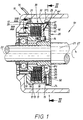
- the first exemplary embodiment of the device shown in FIGS. 1 to 5 shows a friction brake 51, which is designed as an electromagnetic spring pressure brake.
- This brake 51 comprises a first stationary device part 10, which in a housing 11, for. B. a motor end shield, has a magnetic body 12, wherein a coil is integrated in the magnetic body 12.
- This device part 10 is the "stator" of this friction brake 51.
- a pressure ring 15 is connected to the stator 10 in a radially stationary manner, but is axially movable.
- guide pins 14, which pass through axial bores in the pressure ring 15, are arranged in the magnetic body 12.
- the pressure ring 15 is made of magnetizable material and acts as an armature disk with current flow in the coil 13 with the magnetic body 12.
- the pressure ring 15 is under the action of compression springs 16, which strive to push the pressure ring 15 away from the magnetic body 12 in the direction of the shaft axis 22.
- compression springs 16 are provided which sit in axial bores of the magnetic body 12 and exert the axial force illustrated by the arrow P1.
- the other device part of the brake 51 is the rotor 20, which is connected in a rotationally fixed manner to the shaft 21 to be braked during operation.
- the rotation of the shaft 21 is illustrated by a rotary arrow 27 in FIG. 1.
- the rotor 20 not only comprises a disk 23 which is fixedly connected to the shaft 21, but also a cylindrical drum 24 seated on the disk 23.
- the drum 24 carries on its inner cylinder surface a friction element 25, which in the present case consists of a friction lining seated on the cylindrical surface 26.
- a first peculiarity of the invention lies in the fact that in the area of the stator 10 resilient bodies are seated, which in the present case consist of radially resilient tongues 30, which in the following are to be referred to as "spring tongues" for short.
- the spring tongues themselves consist of an elastic material, such as steel, which generates a radial spring force due to the material.
- the spring tongues 30 are anchored directly to the magnetic body 12 of the stator 10 with their one, fixed tongue end 31.
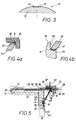
- the spring tongues 30 are in the form of strips. The strip ends forming the fixed tongue end 31 are fastened, as shown in FIG.
- the fixed end 31 of the spring tongues can have a radially inwardly angled end piece 33, which engages behind a correspondingly offset shoulder 19 on the magnet body 12. This facilitates a defined position of the spring tongues 30 when they are mounted on the stator 10.
- the adjoining section 18 of the magnetic body 12 can be offset, over which the adjacent length of the spring tongue 30 projects more or less freely.
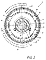
- the spring pressure brake 51 six such spring tongues 30 are arranged on the circumference of the magnetic body 12, but of which, for the sake of simplicity in FIG. 1, only the top spring tongue 30 is shown in longitudinal section, while the remaining five spring tongues 30 were omitted.
- This distribution can be seen from the free tongue ends 32 from FIG. 2, which shows a cross-section through the device along the section line II-II from FIG. 1 in an end view.
- the invention has essentially kink-resistant bodies at the free tongue ends 32, which here consist of isolated, plate-shaped members 40. For reasons to be explained in more detail below, these links 40 are to be referred to as “deflection links”. Every spring tongue 30 is assigned a separate deflection member 40.
- the spring tongues 30 and the associated deflection members 40 form a multi-part pair.
- the pressure ring 15 is provided with a coaxial, front-side annular groove 50, the one groove flank and the groove bottom of FIG. 4b producing supporting surfaces 55 for the one end 41 of the link.
- the deflection member 40 is essentially resistant to buckling and the link end 41 forms with the support surfaces 55 a first hinge point A, for which purpose the edge on this hinge end 41 is expediently rounded. This articulation point A will be referred to as "inner joint" in the following.
- the other link end 42 is supported on the free tongue end 32, for which this too is angled radially inward with an end piece 34.
- the link end 42 In the inside of the angle 35, as can best be seen from FIG. 5, the link end 42 is supported, which, as shown in FIG. 4a, is likewise rounded on its outer edge. This creates a further articulation point B between the inside of the angle 35 and the link end 42, which will hereinafter be referred to as "external joint" for short.
- the two link ends 41, 42 to each other both axially and radially offset, to thereby obtained a helical course of the guide members 40 connected to the shaft axis 22 o results in an axial angle of about 60 in this case.
- the deflection members 40 thus assume a conical shape with respect to the shaft axis 22, the pressure ring-side link ends 41 being on the inside and the tongue-side link ends 42 being on the outside.
- the release position of the brake 51 is shown in FIG. 1. This occurs when the coil 13 has current flowing through it through its supply lines 36, builds up a magnetic field and, as a result, pulls the thrust washer 15 against the magnetic body 12 due to the generated electromagnetic field.
- the axial starting position of the pressure ring 15, designated 15 in FIG. 5, is then present.
- the tongue ends 32 overlap with the drum 24 in the area described with 37 in FIG. 1.
- the friction lining is therefore located in the radial space 47 enclosed between the drum 24 and the tongue ends 32.
- the deflection members 40 are essentially rigid. However, because the spring tongues 30 assigned to them are elastic, they can bend from their original, substantially extended position 30 from FIG. 5 to their radially spread-apart position 30 'by the radial distance y from FIG. 5. This radial distance y overcomes the air gap 28 described above. As a result, the free tongue ends in their spreading position 32 'come into frictional engagement with the drum-side lining 25. Then the brake 51 is in its operative position.
- the pressure members 40 can already be under an axial and radial prestress. This can be done by suitable length dimensioning of the individual deflection members Achieve 40. As a result, the mounting position of the deflecting members 40 is secured at their inner and outer joints A and B. Connections existing between them can also serve to secure the position of the deflection members 40.
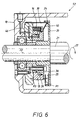
- FIG. 6 shows, in a representation corresponding to FIG. 1, an alternative embodiment of the friction brake, again as a spring pressure brake 52, because compression springs 16 also serve to transfer the pressure ring 15 there into the active position.
- the same reference numerals are used to designate corresponding components as in the first exemplary embodiment of FIGS. 1 to 5, which is why the previous description applies to this extent. It is enough to only consider the differences.
- the pressure ring 15 is designed as a so-called "piston", while a so-called cylinder part 38 is located on the stator 10.
- the compression springs 16 are integrated in axial receptacles of the pressure ring 15 functioning as a piston part.
- a pressure medium chamber 39 is created, which can be acted upon by a pressure medium via various channels 46, which can be seen in FIG. 6.
- the pressure medium introduced generates a pressure medium force P3 which counteracts the pressure spring force P1 and which ensures the ventilation position shown in FIG. 6.
- the axial force P1 of the compression springs 16 develops and leads to the spreading movement of the spring tongues 30 already described in connection with FIG.
- an electromagnetically openable spring pressure brake 53 is again shown, which largely corresponds in terms of structure and mode of operation to the spring pressure brake 51 already described in connection with FIGS. 1 to 5.
- the axially movable pressure ring 15 and the associated magnetic body 12 with the coil 13 are arranged at a greater radial distance from the shaft 21 than the rotor 20 provided with the cylindrical drum 24.
- the spring tongues 30 are one have basically the same structure as in the previous embodiments, not arranged on the outer circumference of the annular magnetic body 12, but on the inner circumference.
- a further row of compression springs 16 ' can be used to increase the axial force P1.
- Another special feature lies in the inclination of the deflection members 40, which is opposite to the previous exemplary embodiments.
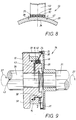
- Fig. 8 illustrates, based on the brake 53, the conditions on a scale that corresponds to reality, where the corresponding air gap 28 can also be seen in the ventilation position, but compared to the now friction-effective cylinder outer surface 29.
- the friction element is in the form of a
- the friction lining 25 is arranged in the radial space 47 between the free tongue ends 32 and the relevant outer cylinder surface 29 of the drum 24.
- this friction lining 25 is not a circumferential ring the cylinder surface 29 is fixed, but is an integral part of the free tongue ends 32; the spring tongues carry the friction lining 25 here.
- something else can be seen from this FIG. 8, which is also realized in an analogous manner in the preceding exemplary embodiments.
- the tongues at least in the overlap region 37 with the rotor drum 24, have a cross-sectional profile which can be seen in FIG. 8 and is designed to conform to the relevant cylinder surface 29.
- the deflection members 40 as can be seen in FIG. 8, are adapted at their supporting edges 48 facing the tongue 32 in conformity with the cylindrical profile of the free tongue ends 32. This shape of the support edge 48 provides surface contact and results in a low surface pressure during operation. This applies mutatis mutandis to the conditions explained in FIG. 2, namely at both link ends 41, 42.
- FIG. 9 shows, as the fourth exemplary embodiment of the device according to the invention, a clutch 54.
- the same terms as in the preceding exemplary embodiments of the brake are to be used to designate corresponding components.
- the same reference numerals are used for this, which is why the previous description applies, at least in an analogous manner. So it can happen that only slightly different terms have to be used for the previously used analog parts.
- a rotation 27 of the input shaft 21 is to be transmitted into a corresponding rotation 57 of an output shaft 56 in the active position, that is to say in the case of a clutch.
- a first device part 10, namely here the first coupling half is rotatably connected to the output shaft 56 and a second device part 20, namely the other coupling half, is rotatably connected to the input shaft 21.
- the two device parts 10, 20 are also axially fixed to their shafts 21 and 56, respectively.
- compression springs 16 are provided on one part of the device 10, but these act in a manner contrary to the previous exemplary embodiments.
- the compression springs 16 endeavor to keep the coupling 54 in its inactive position, namely in a decoupling position.
- the springs 16 are supported on an axially fixed support ring 49 provided with the coupling half 10 and engage in axial bores of the pressure ring 15, which is also designed as a pressure medium piston.
- Axially stepped sections in the device part 10 produce a cylinder part 58 which encloses a pressure medium space 59 with the pressure ring 15.
- the pressure medium is then supplied to the pressure medium chamber 59 via axial and radial channels 43 when the effective coupling position is desired.
- the pressure medium now acts against the restoring action of the compression springs 16 and moves the pressure ring 15 to the outside with an excess axial force P1.
- the axial force P1 is therefore not spring-related, but rather generated by pressure medium. In other respects, however, the analogous relationships described from the preceding exemplary embodiments result.
- the device part 10 is a carrier of a group of essentially axially extending spring tongues 30 and between the free tongue ends 32 and the pressure ring 15 a corresponding group of deflection members 40 is supported here as well.
- the second device part 20 has a drum 24 which carries the friction elements 25 described here on its inner cylinder surface.
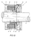
- the spring pressure brake 70 consists of the spring tongue 30 and the associated deflection member 40 existing pair, as best seen in Fig. 11, is integrally formed.
- This assembly is produced from a strip material 60, which in the present case is inherently elastic, that is, for. B. consists of steel. At the points where this product is to be resilient, it runs in a single layer 61, while several layers of the strip material are superimposed in the desired rigid sections.
- the section serving to form the deflection member 40 is formed from two layers 61, 62.
- This second layer 62 can extend with an end piece 63, according to FIG. 11, into the end region 32 of the tongue 30.
- the strip material 60 has thus become a one-piece fold-bend product 66, which produces the pair of links 30, 40 and is installed in the device in the following special way.
- the leg of the product 66 used to form the tongue 30 is inserted with its tongue end 31 into the axial groove 17 already mentioned in the previous exemplary embodiment and is initially axially displaceable therein.
- the end 41 of the section used to form the deflection member 40 is rounded, as illustrated in FIG. 12, and engages in a correspondingly profiled concave groove 64 in the pressure ring 15.
- the pressure ring 15 is provided with a shoulder 65.
- the inner joint A already described in connection with the first exemplary embodiment is created there.
- the angle 67 between the two legs 30, 40 of the product 66 is smaller than in the later installed state.
- the leg 30 of the product 66 is set to a defined effective length 68 which can be seen in FIG. 11.
- the tongue 30 projects out of the guide groove 17 by this length 68 and is radially elastically flexible in this length piece in the manner already described.
- This effective tongue length 68 is fixed. This is done by e.g. B. the groove 17 compresses, whereby the spring end 31 inserted there becomes stationary.
- the angle 67 between the two legs 30, 40 of the product 66 is larger. Because the angle 67 tends to shrink, a spring preload results in the installed state.
- Fig. 11 shows that the spring tongue 30 carrier in the present case Friction elements 25 'is.
- the friction element 25 ' is located in that end section where the section 63 of the second layer 62 of the strip material 60 also appears.
- the end piece of the spring tongue 30, where the friction element 25 'sits, is stiffened. This can also be seen from the cross-sectional view of FIG. 13.
- the strip material 60 is flat, but the friction element 25 'fastened on the layers 61, 62 has a special cross-sectional profile.
- the friction element 25 ' has a different covering height in places and produced a cylindrically curved friction active surface 69 in the radial peripheral region.
- This curvature 69 conforms to the cylinder inner surface 26 of the drum 24, which is also shown in FIG. 10 and is indicated by dash-dotted lines.
- This drum 24 sits on the shaft 21 in a rotationally fixed manner by means of a press ring 71.
- An elastic spring washer 72 is used to arrange and guide the pressure ring 15, the position of which can best be seen from FIG. 11. It is located between the pressure ring 15 on the one hand and the housing of the magnetic body 12 on the other hand, which contains the electromagnetic coil 13.
- the compression springs 16 already mentioned in the first exemplary embodiment are supported on the spring washer 72.
- the spring washer 72 is attached in places by bolts 73 to the pressure ring 15. At radially offset points, the spring washer 72 is fastened to the magnet body housing 12 by means of screws 75.
Landscapes
- Engineering & Computer Science (AREA)
- General Engineering & Computer Science (AREA)
- Mechanical Engineering (AREA)
- Physics & Mathematics (AREA)
- Electromagnetism (AREA)
- Braking Arrangements (AREA)
- Hydraulic Clutches, Magnetic Clutches, Fluid Clutches, And Fluid Joints (AREA)
- Mechanical Operated Clutches (AREA)
Applications Claiming Priority (2)
| Application Number | Priority Date | Filing Date | Title |
|---|---|---|---|
| DE19613763 | 1996-04-06 | ||
| DE19613763A DE19613763C1 (de) | 1996-04-06 | 1996-04-06 | Schaltbare, bremswirksame oder kupplungswirksame Vorrichtung, wie eine Reibungsbremse oder eine Reibungskupplung |
Publications (3)
| Publication Number | Publication Date |
|---|---|
| EP0800016A2 true EP0800016A2 (fr) | 1997-10-08 |
| EP0800016A3 EP0800016A3 (fr) | 2000-04-12 |
| EP0800016B1 EP0800016B1 (fr) | 2002-04-24 |
Family
ID=7790630
Family Applications (1)
| Application Number | Title | Priority Date | Filing Date |
|---|---|---|---|
| EP97104132A Expired - Lifetime EP0800016B1 (fr) | 1996-04-06 | 1997-03-12 | Dispositif commutable agissant comme frein ou embrayage, tel que frein ou embrayage à friction |
Country Status (5)
| Country | Link |
|---|---|
| US (1) | US5873443A (fr) |
| EP (1) | EP0800016B1 (fr) |
| JP (1) | JP3864356B2 (fr) |
| DE (2) | DE19613763C1 (fr) |
| ES (1) | ES2172710T3 (fr) |
Cited By (2)
| Publication number | Priority date | Publication date | Assignee | Title |
|---|---|---|---|---|
| DE19834093A1 (de) * | 1998-07-29 | 2000-02-17 | Brinkmann Gmbh & Co Kg | Elektromagnetisch lüftbare Federdruckbremse |
| DE10222101A1 (de) * | 2002-05-17 | 2003-11-27 | Mayr Christian Gmbh & Co Kg | Elektromagnetisch gelüftete Reibungsbremse mit einer Spannzange zum gleichzeitigen Abbremsen eines Antriebsteils in Umfangs- und Axialrichtung |
Families Citing this family (12)
| Publication number | Priority date | Publication date | Assignee | Title |
|---|---|---|---|---|
| DE19850552B4 (de) * | 1998-04-17 | 2009-09-24 | GIF - Gesellschaft für Industrieforschung mbH | Betätigung für eine achsial wirksame Kupplungsdruckplatte sowie Ausrückeeinheit für eine Fahrzeugkupplung |
| US6336530B1 (en) * | 2000-04-07 | 2002-01-08 | Timothy L. Hottle | Vehicle brake assembly |
| US6851526B2 (en) * | 2002-11-20 | 2005-02-08 | Deere & Company | Actuator assembly |
| DE102006024276A1 (de) | 2006-05-24 | 2007-11-29 | Zf Friedrichshafen Ag | Elektromagnetisch betätigbare Einheit, insbesondere eine Kupplung/Bremse bzw. Sperre |
| JP5003912B2 (ja) * | 2008-09-19 | 2012-08-22 | 株式会社安川電機 | 無励磁作動型ブレーキおよびそれを用いたサーボモータ |
| MD4079C1 (ro) * | 2009-02-06 | 2011-07-31 | Сергей БУРЛАК | Dispozitiv de utilizare a energiei de frânare la autovehicule |
| DE102012004467A1 (de) * | 2012-03-08 | 2013-09-12 | Peiseler Gmbh & Co. Kg | Klemmvorrichtung und elastisches Klemmelement |
| DE102013220443A1 (de) * | 2013-10-10 | 2015-04-16 | Zf Friedrichshafen Ag | Linearstellvorrichtung mit Rückstellfeder |
| US10518761B2 (en) | 2016-07-01 | 2019-12-31 | Akebono Brake Industry Co., Ltd | Electric park brake with electromagnetic brake |
| DE102016012643B4 (de) * | 2016-10-24 | 2018-07-12 | Sew-Eurodrive Gmbh & Co Kg | Elektromagnetisch betätigbare Bremsanordnung |
| CN108061107A (zh) * | 2017-12-26 | 2018-05-22 | 无锡海核装备科技有限公司 | 被动式自动连接与解锁装置 |
| KR102127054B1 (ko) * | 2018-12-20 | 2020-06-25 | 주식회사 두산 | 전기차용 전자 브레이크 시스템 |
Family Cites Families (9)
| Publication number | Priority date | Publication date | Assignee | Title |
|---|---|---|---|---|
| US2286532A (en) * | 1940-08-02 | 1942-06-16 | Phelps M Freer | Friction coupling |
| US2284193A (en) * | 1940-08-02 | 1942-05-26 | Phelps M Freer | Friction coupling |
| US3233710A (en) * | 1963-06-25 | 1966-02-08 | Cons Electronics Ind | Electromagnetic clutch |
| DE1231496B (de) * | 1964-04-25 | 1966-12-29 | Fichtel & Sachs Ag | Temperaturabhaengig schaltende Reibungskupplung |
| DE6607298U (de) * | 1967-10-07 | 1971-02-18 | Dingler Werke Ag | Sperrvorrichtung in form einer spreizringbremse fuer hydraulisch oder pneumatisch betaetigte verstellaggregate |
| US3640363A (en) * | 1969-12-23 | 1972-02-08 | Gen Electric | Friction coupling |
| US3789965A (en) * | 1972-06-21 | 1974-02-05 | Gen Motors Corp | Vacuum clutch actuator |
| DE2814200C2 (de) * | 1978-04-03 | 1983-02-24 | Maschinenfabrik Hans Lenze Kg, 4923 Extertal | Federkraftbremse mit Elektromagnetlüftung |
| US4679745A (en) * | 1985-07-03 | 1987-07-14 | Gold Star Co., Ltd. | Reel brake device of a videocassette recorder |
-
1996
- 1996-04-06 DE DE19613763A patent/DE19613763C1/de not_active Expired - Fee Related
-
1997
- 1997-03-12 DE DE59707084T patent/DE59707084D1/de not_active Expired - Lifetime
- 1997-03-12 ES ES97104132T patent/ES2172710T3/es not_active Expired - Lifetime
- 1997-03-12 EP EP97104132A patent/EP0800016B1/fr not_active Expired - Lifetime
- 1997-03-19 JP JP10507997A patent/JP3864356B2/ja not_active Expired - Fee Related
- 1997-04-04 US US08/833,025 patent/US5873443A/en not_active Expired - Fee Related
Cited By (4)
| Publication number | Priority date | Publication date | Assignee | Title |
|---|---|---|---|---|
| DE19834093A1 (de) * | 1998-07-29 | 2000-02-17 | Brinkmann Gmbh & Co Kg | Elektromagnetisch lüftbare Federdruckbremse |
| DE19834093C2 (de) * | 1998-07-29 | 2000-09-07 | Brinkmann Gmbh & Co Kg | Elektromagnetisch lüftbare Federdruckbremse |
| DE10222101A1 (de) * | 2002-05-17 | 2003-11-27 | Mayr Christian Gmbh & Co Kg | Elektromagnetisch gelüftete Reibungsbremse mit einer Spannzange zum gleichzeitigen Abbremsen eines Antriebsteils in Umfangs- und Axialrichtung |
| DE10222101B4 (de) * | 2002-05-17 | 2015-09-10 | Chr. Mayr Gmbh + Co Kg | Elektromagnetisch gelüftete Reibungsbremse mit einer Spannzange zum gleichzeitigen Abbremsen eines Antriebsteils in Umfangs- und Axialrichtung |
Also Published As
| Publication number | Publication date |
|---|---|
| JPH1061682A (ja) | 1998-03-06 |
| ES2172710T3 (es) | 2002-10-01 |
| EP0800016A3 (fr) | 2000-04-12 |
| JP3864356B2 (ja) | 2006-12-27 |
| DE59707084D1 (de) | 2002-05-29 |
| DE19613763C1 (de) | 1997-05-07 |
| US5873443A (en) | 1999-02-23 |
| EP0800016B1 (fr) | 2002-04-24 |
Similar Documents
| Publication | Publication Date | Title |
|---|---|---|
| DE102011050814B3 (de) | Welle mit einem Lager | |
| EP0800016A2 (fr) | Dispositif commutable agissant comme frein ou embrayage, tel que frein ou embrayage à friction | |
| DE102016205794A1 (de) | Antriebseinheit für eine Aufzugsanlage | |
| DE7822318U1 (de) | Elektromagnetische bremse | |
| DE3046156C2 (de) | Betätigungsvorrichtung für Scheibenbremsen | |
| EP0374268A1 (fr) | Dispositif pour le rattrapage automatique du jeu dans un assemblage d'embrayage et/ou de frein | |
| WO2020088873A1 (fr) | Ensemble d'embrayage pour chaîne cinématique de véhicule automobile et chaîne cinématique de véhicule automobile | |
| DE2402604A1 (de) | Reibungsueberlastkupplung | |
| EP1000829A1 (fr) | Essieu moteur | |
| DE102016201271A1 (de) | Bremssystem für Achse | |
| DE102014105607A1 (de) | Bremseinrichtung mit einer elektromagnetisch lösbaren Feststellbremse und einer hydraulischen Betriebsbremse | |
| WO2010108509A1 (fr) | Entraînement linéaire électrique | |
| DE3911427A1 (de) | Lamellenbremse | |
| DE29706124U1 (de) | Federdruckbremse | |
| EP3966409B1 (fr) | Dispositif pour poser des objets au moyen d'un entraînement orienté horizontalement | |
| DE102011102904B4 (de) | Bremssystem | |
| DE2636444B2 (de) | Führung des zweigeteilten Sattels einer Schwimmsattel-Teilbelag-Scheibenbremse | |
| DE102017108744A1 (de) | Dichtungseinheit | |
| DE202021103823U1 (de) | Entkoppelanordnung für Radnabengetriebe | |
| DE102024104224B3 (de) | Bremseinrichtung für eine Bergbaumaschine | |
| DE19823730B4 (de) | Verteilergetriebe insbesondere für eine Schiebedach-Anordnung eines Fahrzeuges | |
| DE202004008714U1 (de) | Bremsvorrichtung für einen elektrischen Antriebsmotor und Möbel | |
| EP0919741A1 (fr) | Dispositif d'engagement et de désengagement d'un embrayage | |
| EP3513090B1 (fr) | Unité de réglage pour freins à tambour | |
| WO2025031531A1 (fr) | Roue libre déplaçable comprenant un embrayage à friction |
Legal Events
| Date | Code | Title | Description |
|---|---|---|---|
| PUAI | Public reference made under article 153(3) epc to a published international application that has entered the european phase |
Free format text: ORIGINAL CODE: 0009012 |
|
| AK | Designated contracting states |
Kind code of ref document: A2 Designated state(s): DE ES FR GB IT |
|
| PUAL | Search report despatched |
Free format text: ORIGINAL CODE: 0009013 |
|
| AK | Designated contracting states |
Kind code of ref document: A3 Designated state(s): DE ES FR GB IT |
|
| 17P | Request for examination filed |
Effective date: 20000524 |
|
| 17Q | First examination report despatched |
Effective date: 20010117 |
|
| GRAG | Despatch of communication of intention to grant |
Free format text: ORIGINAL CODE: EPIDOS AGRA |
|
| GRAG | Despatch of communication of intention to grant |
Free format text: ORIGINAL CODE: EPIDOS AGRA |
|
| GRAH | Despatch of communication of intention to grant a patent |
Free format text: ORIGINAL CODE: EPIDOS IGRA |
|
| REG | Reference to a national code |
Ref country code: GB Ref legal event code: IF02 |
|
| GRAH | Despatch of communication of intention to grant a patent |
Free format text: ORIGINAL CODE: EPIDOS IGRA |
|
| GRAA | (expected) grant |
Free format text: ORIGINAL CODE: 0009210 |
|
| AK | Designated contracting states |
Kind code of ref document: B1 Designated state(s): DE ES FR GB IT |
|
| REG | Reference to a national code |
Ref country code: GB Ref legal event code: FG4D Free format text: NOT ENGLISH |
|
| GBT | Gb: translation of ep patent filed (gb section 77(6)(a)/1977) |
Effective date: 20020426 |
|
| REF | Corresponds to: |
Ref document number: 59707084 Country of ref document: DE Date of ref document: 20020529 |
|
| ET | Fr: translation filed | ||
| REG | Reference to a national code |
Ref country code: ES Ref legal event code: FG2A Ref document number: 2172710 Country of ref document: ES Kind code of ref document: T3 |
|
| PLBE | No opposition filed within time limit |
Free format text: ORIGINAL CODE: 0009261 |
|
| STAA | Information on the status of an ep patent application or granted ep patent |
Free format text: STATUS: NO OPPOSITION FILED WITHIN TIME LIMIT |
|
| 26N | No opposition filed |
Effective date: 20030127 |
|
| PGFP | Annual fee paid to national office [announced via postgrant information from national office to epo] |
Ref country code: ES Payment date: 20100308 Year of fee payment: 14 |
|
| PGFP | Annual fee paid to national office [announced via postgrant information from national office to epo] |
Ref country code: IT Payment date: 20100323 Year of fee payment: 14 Ref country code: FR Payment date: 20100408 Year of fee payment: 14 |
|
| PGFP | Annual fee paid to national office [announced via postgrant information from national office to epo] |
Ref country code: GB Payment date: 20100317 Year of fee payment: 14 |
|
| PGFP | Annual fee paid to national office [announced via postgrant information from national office to epo] |
Ref country code: DE Payment date: 20100308 Year of fee payment: 14 |
|
| GBPC | Gb: european patent ceased through non-payment of renewal fee |
Effective date: 20110312 |
|
| REG | Reference to a national code |
Ref country code: FR Ref legal event code: ST Effective date: 20111130 |
|
| PG25 | Lapsed in a contracting state [announced via postgrant information from national office to epo] |
Ref country code: DE Free format text: LAPSE BECAUSE OF NON-PAYMENT OF DUE FEES Effective date: 20111001 Ref country code: FR Free format text: LAPSE BECAUSE OF NON-PAYMENT OF DUE FEES Effective date: 20110331 |
|
| REG | Reference to a national code |
Ref country code: DE Ref legal event code: R119 Ref document number: 59707084 Country of ref document: DE Effective date: 20111001 |
|
| PG25 | Lapsed in a contracting state [announced via postgrant information from national office to epo] |
Ref country code: GB Free format text: LAPSE BECAUSE OF NON-PAYMENT OF DUE FEES Effective date: 20110312 Ref country code: IT Free format text: LAPSE BECAUSE OF NON-PAYMENT OF DUE FEES Effective date: 20110312 |
|
| REG | Reference to a national code |
Ref country code: ES Ref legal event code: FD2A Effective date: 20120423 |
|
| PG25 | Lapsed in a contracting state [announced via postgrant information from national office to epo] |
Ref country code: ES Free format text: LAPSE BECAUSE OF NON-PAYMENT OF DUE FEES Effective date: 20110313 |