EP0800489B1 - Evaporateur pelliculaire vertical, a lit fixe, pour composes depourvus d'halogenure et contenant du silicium - Google Patents
Evaporateur pelliculaire vertical, a lit fixe, pour composes depourvus d'halogenure et contenant du silicium Download PDFInfo
- Publication number
- EP0800489B1 EP0800489B1 EP95944370A EP95944370A EP0800489B1 EP 0800489 B1 EP0800489 B1 EP 0800489B1 EP 95944370 A EP95944370 A EP 95944370A EP 95944370 A EP95944370 A EP 95944370A EP 0800489 B1 EP0800489 B1 EP 0800489B1
- Authority
- EP
- European Patent Office
- Prior art keywords
- gas
- reactant
- packed
- vapor
- column
- Prior art date
- Legal status (The legal status is an assumption and is not a legal conclusion. Google has not performed a legal analysis and makes no representation as to the accuracy of the status listed.)
- Expired - Lifetime
Links
- 239000002210 silicon-based material Substances 0.000 title 1
- 239000000376 reactant Substances 0.000 claims abstract description 113
- 239000007789 gas Substances 0.000 claims abstract description 109
- 239000007788 liquid Substances 0.000 claims abstract description 74
- 239000000203 mixture Substances 0.000 claims abstract description 51
- HMMGMWAXVFQUOA-UHFFFAOYSA-N octamethylcyclotetrasiloxane Chemical compound C[Si]1(C)O[Si](C)(C)O[Si](C)(C)O[Si](C)(C)O1 HMMGMWAXVFQUOA-UHFFFAOYSA-N 0.000 claims abstract description 24
- QVGXLLKOCUKJST-UHFFFAOYSA-N atomic oxygen Chemical compound [O] QVGXLLKOCUKJST-UHFFFAOYSA-N 0.000 claims abstract description 22
- 239000001301 oxygen Substances 0.000 claims abstract description 22
- 229910052760 oxygen Inorganic materials 0.000 claims abstract description 22
- -1 e.g. Substances 0.000 claims abstract description 6
- 238000000034 method Methods 0.000 claims description 20
- 238000010438 heat treatment Methods 0.000 claims description 19
- VYPSYNLAJGMNEJ-UHFFFAOYSA-N Silicium dioxide Chemical compound O=[Si]=O VYPSYNLAJGMNEJ-UHFFFAOYSA-N 0.000 claims description 17
- 230000008016 vaporization Effects 0.000 claims description 13
- 239000012530 fluid Substances 0.000 claims description 9
- 239000000377 silicon dioxide Substances 0.000 claims description 8
- 235000012239 silicon dioxide Nutrition 0.000 claims description 8
- 238000009689 gas atomisation Methods 0.000 claims description 7
- 238000004519 manufacturing process Methods 0.000 claims description 7
- 239000000835 fiber Substances 0.000 claims description 5
- 239000002245 particle Substances 0.000 claims description 5
- 230000003287 optical effect Effects 0.000 claims description 4
- 230000015572 biosynthetic process Effects 0.000 claims description 2
- 238000005507 spraying Methods 0.000 claims description 2
- 239000006200 vaporizer Substances 0.000 abstract description 43
- 239000003921 oil Substances 0.000 abstract description 12
- 230000008859 change Effects 0.000 abstract description 10
- XUIMIQQOPSSXEZ-UHFFFAOYSA-N Silicon Chemical compound [Si] XUIMIQQOPSSXEZ-UHFFFAOYSA-N 0.000 abstract description 7
- 229910052710 silicon Inorganic materials 0.000 abstract description 7
- 239000010703 silicon Substances 0.000 abstract description 7
- 239000007921 spray Substances 0.000 abstract description 5
- 239000004071 soot Substances 0.000 abstract description 3
- 239000000463 material Substances 0.000 description 25
- 239000007791 liquid phase Substances 0.000 description 12
- 239000012071 phase Substances 0.000 description 11
- 238000012856 packing Methods 0.000 description 10
- 239000002994 raw material Substances 0.000 description 9
- 238000009834 vaporization Methods 0.000 description 9
- 239000012535 impurity Substances 0.000 description 6
- 238000006116 polymerization reaction Methods 0.000 description 6
- 230000008569 process Effects 0.000 description 6
- 150000004820 halides Chemical class 0.000 description 5
- 238000012546 transfer Methods 0.000 description 5
- 229910003910 SiCl4 Inorganic materials 0.000 description 4
- 239000012159 carrier gas Substances 0.000 description 4
- 238000001914 filtration Methods 0.000 description 4
- 239000011148 porous material Substances 0.000 description 4
- FDNAPBUWERUEDA-UHFFFAOYSA-N silicon tetrachloride Chemical compound Cl[Si](Cl)(Cl)Cl FDNAPBUWERUEDA-UHFFFAOYSA-N 0.000 description 4
- 238000013459 approach Methods 0.000 description 3
- 239000000919 ceramic Substances 0.000 description 3
- 238000001704 evaporation Methods 0.000 description 3
- 239000000499 gel Substances 0.000 description 3
- 230000009467 reduction Effects 0.000 description 3
- IJGRMHOSHXDMSA-UHFFFAOYSA-N Atomic nitrogen Chemical compound N#N IJGRMHOSHXDMSA-UHFFFAOYSA-N 0.000 description 2
- VEXZGXHMUGYJMC-UHFFFAOYSA-N Hydrochloric acid Chemical compound Cl VEXZGXHMUGYJMC-UHFFFAOYSA-N 0.000 description 2
- 238000009835 boiling Methods 0.000 description 2
- 239000006227 byproduct Substances 0.000 description 2
- 238000010276 construction Methods 0.000 description 2
- 230000008030 elimination Effects 0.000 description 2
- 238000003379 elimination reaction Methods 0.000 description 2
- 230000008020 evaporation Effects 0.000 description 2
- 239000011521 glass Substances 0.000 description 2
- 239000011491 glass wool Substances 0.000 description 2
- 239000011261 inert gas Substances 0.000 description 2
- 229920002545 silicone oil Polymers 0.000 description 2
- 229910001220 stainless steel Inorganic materials 0.000 description 2
- 239000010935 stainless steel Substances 0.000 description 2
- 239000011324 bead Substances 0.000 description 1
- 238000005229 chemical vapour deposition Methods 0.000 description 1
- 238000005253 cladding Methods 0.000 description 1
- 238000004140 cleaning Methods 0.000 description 1
- 238000005336 cracking Methods 0.000 description 1
- 238000000354 decomposition reaction Methods 0.000 description 1
- 238000000151 deposition Methods 0.000 description 1
- 230000008021 deposition Effects 0.000 description 1
- 238000010586 diagram Methods 0.000 description 1
- 238000009792 diffusion process Methods 0.000 description 1
- 238000009826 distribution Methods 0.000 description 1
- 239000002019 doping agent Substances 0.000 description 1
- 238000005516 engineering process Methods 0.000 description 1
- 238000003912 environmental pollution Methods 0.000 description 1
- 239000010408 film Substances 0.000 description 1
- 239000005350 fused silica glass Substances 0.000 description 1
- 238000012423 maintenance Methods 0.000 description 1
- 230000007246 mechanism Effects 0.000 description 1
- 239000002184 metal Substances 0.000 description 1
- 229910052751 metal Inorganic materials 0.000 description 1
- 229910052757 nitrogen Inorganic materials 0.000 description 1
- 230000000737 periodic effect Effects 0.000 description 1
- 238000002360 preparation method Methods 0.000 description 1
- 229920006395 saturated elastomer Polymers 0.000 description 1
- 230000035945 sensitivity Effects 0.000 description 1
- 238000000926 separation method Methods 0.000 description 1
- 239000007858 starting material Substances 0.000 description 1
- 239000000126 substance Substances 0.000 description 1
- 238000012360 testing method Methods 0.000 description 1
- 239000010409 thin film Substances 0.000 description 1
- 238000009827 uniform distribution Methods 0.000 description 1
- 238000011144 upstream manufacturing Methods 0.000 description 1
- 238000007740 vapor deposition Methods 0.000 description 1
- 238000001947 vapour-phase growth Methods 0.000 description 1
- 239000002699 waste material Substances 0.000 description 1
- 238000009736 wetting Methods 0.000 description 1
Images


Classifications
-
- C—CHEMISTRY; METALLURGY
- C23—COATING METALLIC MATERIAL; COATING MATERIAL WITH METALLIC MATERIAL; CHEMICAL SURFACE TREATMENT; DIFFUSION TREATMENT OF METALLIC MATERIAL; COATING BY VACUUM EVAPORATION, BY SPUTTERING, BY ION IMPLANTATION OR BY CHEMICAL VAPOUR DEPOSITION, IN GENERAL; INHIBITING CORROSION OF METALLIC MATERIAL OR INCRUSTATION IN GENERAL
- C23C—COATING METALLIC MATERIAL; COATING MATERIAL WITH METALLIC MATERIAL; SURFACE TREATMENT OF METALLIC MATERIAL BY DIFFUSION INTO THE SURFACE, BY CHEMICAL CONVERSION OR SUBSTITUTION; COATING BY VACUUM EVAPORATION, BY SPUTTERING, BY ION IMPLANTATION OR BY CHEMICAL VAPOUR DEPOSITION, IN GENERAL
- C23C16/00—Chemical coating by decomposition of gaseous compounds, without leaving reaction products of surface material in the coating, i.e. chemical vapour deposition [CVD] processes
- C23C16/44—Chemical coating by decomposition of gaseous compounds, without leaving reaction products of surface material in the coating, i.e. chemical vapour deposition [CVD] processes characterised by the method of coating
- C23C16/448—Chemical coating by decomposition of gaseous compounds, without leaving reaction products of surface material in the coating, i.e. chemical vapour deposition [CVD] processes characterised by the method of coating characterised by the method used for generating reactive gas streams, e.g. by evaporation or sublimation of precursor materials
- C23C16/4481—Chemical coating by decomposition of gaseous compounds, without leaving reaction products of surface material in the coating, i.e. chemical vapour deposition [CVD] processes characterised by the method of coating characterised by the method used for generating reactive gas streams, e.g. by evaporation or sublimation of precursor materials by evaporation using carrier gas in contact with the source material
- C23C16/4483—Chemical coating by decomposition of gaseous compounds, without leaving reaction products of surface material in the coating, i.e. chemical vapour deposition [CVD] processes characterised by the method of coating characterised by the method used for generating reactive gas streams, e.g. by evaporation or sublimation of precursor materials by evaporation using carrier gas in contact with the source material using a porous body
-
- B—PERFORMING OPERATIONS; TRANSPORTING
- B01—PHYSICAL OR CHEMICAL PROCESSES OR APPARATUS IN GENERAL
- B01D—SEPARATION
- B01D3/00—Distillation or related exchange processes in which liquids are contacted with gaseous media, e.g. stripping
- B01D3/34—Distillation or related exchange processes in which liquids are contacted with gaseous media, e.g. stripping with one or more auxiliary substances
- B01D3/343—Distillation or related exchange processes in which liquids are contacted with gaseous media, e.g. stripping with one or more auxiliary substances the substance being a gas
- B01D3/346—Distillation or related exchange processes in which liquids are contacted with gaseous media, e.g. stripping with one or more auxiliary substances the substance being a gas the gas being used for removing vapours, e.g. transport gas
-
- C—CHEMISTRY; METALLURGY
- C03—GLASS; MINERAL OR SLAG WOOL
- C03B—MANUFACTURE, SHAPING, OR SUPPLEMENTARY PROCESSES
- C03B19/00—Other methods of shaping glass
- C03B19/14—Other methods of shaping glass by gas- or vapour- phase reaction processes
- C03B19/1415—Reactant delivery systems
-
- C—CHEMISTRY; METALLURGY
- C03—GLASS; MINERAL OR SLAG WOOL
- C03B—MANUFACTURE, SHAPING, OR SUPPLEMENTARY PROCESSES
- C03B37/00—Manufacture or treatment of flakes, fibres, or filaments from softened glass, minerals, or slags
- C03B37/01—Manufacture of glass fibres or filaments
- C03B37/012—Manufacture of preforms for drawing fibres or filaments
- C03B37/014—Manufacture of preforms for drawing fibres or filaments made entirely or partially by chemical means, e.g. vapour phase deposition of bulk porous glass either by outside vapour deposition [OVD], or by outside vapour phase oxidation [OVPO] or by vapour axial deposition [VAD]
- C03B37/01413—Reactant delivery systems
-
- C—CHEMISTRY; METALLURGY
- C23—COATING METALLIC MATERIAL; COATING MATERIAL WITH METALLIC MATERIAL; CHEMICAL SURFACE TREATMENT; DIFFUSION TREATMENT OF METALLIC MATERIAL; COATING BY VACUUM EVAPORATION, BY SPUTTERING, BY ION IMPLANTATION OR BY CHEMICAL VAPOUR DEPOSITION, IN GENERAL; INHIBITING CORROSION OF METALLIC MATERIAL OR INCRUSTATION IN GENERAL
- C23C—COATING METALLIC MATERIAL; COATING MATERIAL WITH METALLIC MATERIAL; SURFACE TREATMENT OF METALLIC MATERIAL BY DIFFUSION INTO THE SURFACE, BY CHEMICAL CONVERSION OR SUBSTITUTION; COATING BY VACUUM EVAPORATION, BY SPUTTERING, BY ION IMPLANTATION OR BY CHEMICAL VAPOUR DEPOSITION, IN GENERAL
- C23C16/00—Chemical coating by decomposition of gaseous compounds, without leaving reaction products of surface material in the coating, i.e. chemical vapour deposition [CVD] processes
- C23C16/22—Chemical coating by decomposition of gaseous compounds, without leaving reaction products of surface material in the coating, i.e. chemical vapour deposition [CVD] processes characterised by the deposition of inorganic material, other than metallic material
- C23C16/30—Deposition of compounds, mixtures or solid solutions, e.g. borides, carbides, nitrides
- C23C16/40—Oxides
- C23C16/401—Oxides containing silicon
- C23C16/402—Silicon dioxide
-
- C—CHEMISTRY; METALLURGY
- C23—COATING METALLIC MATERIAL; COATING MATERIAL WITH METALLIC MATERIAL; CHEMICAL SURFACE TREATMENT; DIFFUSION TREATMENT OF METALLIC MATERIAL; COATING BY VACUUM EVAPORATION, BY SPUTTERING, BY ION IMPLANTATION OR BY CHEMICAL VAPOUR DEPOSITION, IN GENERAL; INHIBITING CORROSION OF METALLIC MATERIAL OR INCRUSTATION IN GENERAL
- C23C—COATING METALLIC MATERIAL; COATING MATERIAL WITH METALLIC MATERIAL; SURFACE TREATMENT OF METALLIC MATERIAL BY DIFFUSION INTO THE SURFACE, BY CHEMICAL CONVERSION OR SUBSTITUTION; COATING BY VACUUM EVAPORATION, BY SPUTTERING, BY ION IMPLANTATION OR BY CHEMICAL VAPOUR DEPOSITION, IN GENERAL
- C23C16/00—Chemical coating by decomposition of gaseous compounds, without leaving reaction products of surface material in the coating, i.e. chemical vapour deposition [CVD] processes
- C23C16/44—Chemical coating by decomposition of gaseous compounds, without leaving reaction products of surface material in the coating, i.e. chemical vapour deposition [CVD] processes characterised by the method of coating
- C23C16/448—Chemical coating by decomposition of gaseous compounds, without leaving reaction products of surface material in the coating, i.e. chemical vapour deposition [CVD] processes characterised by the method of coating characterised by the method used for generating reactive gas streams, e.g. by evaporation or sublimation of precursor materials
- C23C16/4481—Chemical coating by decomposition of gaseous compounds, without leaving reaction products of surface material in the coating, i.e. chemical vapour deposition [CVD] processes characterised by the method of coating characterised by the method used for generating reactive gas streams, e.g. by evaporation or sublimation of precursor materials by evaporation using carrier gas in contact with the source material
-
- C—CHEMISTRY; METALLURGY
- C03—GLASS; MINERAL OR SLAG WOOL
- C03B—MANUFACTURE, SHAPING, OR SUPPLEMENTARY PROCESSES
- C03B2207/00—Glass deposition burners
- C03B2207/30—For glass precursor of non-standard type, e.g. solid SiH3F
- C03B2207/32—Non-halide
-
- C—CHEMISTRY; METALLURGY
- C03—GLASS; MINERAL OR SLAG WOOL
- C03B—MANUFACTURE, SHAPING, OR SUPPLEMENTARY PROCESSES
- C03B2207/00—Glass deposition burners
- C03B2207/80—Feeding the burner or the burner-heated deposition site
- C03B2207/85—Feeding the burner or the burner-heated deposition site with vapour generated from liquid glass precursors, e.g. directly by heating the liquid
-
- Y—GENERAL TAGGING OF NEW TECHNOLOGICAL DEVELOPMENTS; GENERAL TAGGING OF CROSS-SECTIONAL TECHNOLOGIES SPANNING OVER SEVERAL SECTIONS OF THE IPC; TECHNICAL SUBJECTS COVERED BY FORMER USPC CROSS-REFERENCE ART COLLECTIONS [XRACs] AND DIGESTS
- Y10—TECHNICAL SUBJECTS COVERED BY FORMER USPC
- Y10S—TECHNICAL SUBJECTS COVERED BY FORMER USPC CROSS-REFERENCE ART COLLECTIONS [XRACs] AND DIGESTS
- Y10S159/00—Concentrating evaporators
- Y10S159/01—Electric heat
-
- Y—GENERAL TAGGING OF NEW TECHNOLOGICAL DEVELOPMENTS; GENERAL TAGGING OF CROSS-SECTIONAL TECHNOLOGIES SPANNING OVER SEVERAL SECTIONS OF THE IPC; TECHNICAL SUBJECTS COVERED BY FORMER USPC CROSS-REFERENCE ART COLLECTIONS [XRACs] AND DIGESTS
- Y10—TECHNICAL SUBJECTS COVERED BY FORMER USPC
- Y10S—TECHNICAL SUBJECTS COVERED BY FORMER USPC CROSS-REFERENCE ART COLLECTIONS [XRACs] AND DIGESTS
- Y10S159/00—Concentrating evaporators
- Y10S159/32—Indirect heat exchange
-
- Y—GENERAL TAGGING OF NEW TECHNOLOGICAL DEVELOPMENTS; GENERAL TAGGING OF CROSS-SECTIONAL TECHNOLOGIES SPANNING OVER SEVERAL SECTIONS OF THE IPC; TECHNICAL SUBJECTS COVERED BY FORMER USPC CROSS-REFERENCE ART COLLECTIONS [XRACs] AND DIGESTS
- Y10—TECHNICAL SUBJECTS COVERED BY FORMER USPC
- Y10S—TECHNICAL SUBJECTS COVERED BY FORMER USPC CROSS-REFERENCE ART COLLECTIONS [XRACs] AND DIGESTS
- Y10S261/00—Gas and liquid contact apparatus
- Y10S261/65—Vaporizers
Definitions
- This invention relates to vaporizers (evaporators) for use in producing preforms which can be used to produce optical or acoustic waveguide fibers either directly or through intermediate production of core cane.
- halide-containing raw materials such as, SiCl 4 or mixtures of SiCl 4 with various dopants
- MCVD modified chemical vapor deposition
- VAD vapor axial deposition
- OVD outside vapor deposition
- the halide-containing raw materials are vaporized and reacted with oxygen to form oxide particles which are deposited on the inside of a fused-silica tube.
- vaporized, halide-containing raw materials are hydrolyzed in a burner to produce soot particles which are collected on a rotating starting rod (bait tube) in the case of VAD or a rotating mandrel in the case of OVD.
- the cladding portion of the preform is deposited on a previously-formed core preform, rather than on a mandrel.
- U.S. Patent No 4,212,663 discloses a vertically oriented packed-bed column with a top liquid feed and a bottom gas feed.
- the column is provided with a vaporization system for a liquid reactant, e.g. SiCl 4 , in which a heated reactant is deposited on the top of the column containing a porous packing material and carrier gas, e.g., oxygen, is bubbled through a reservoir of the liquid reactant and then up through the column.
- the Aslami system can include a second, heated column located above the first column which serves to: (1) ensure that the carrier gas is fully saturated, and (2) prevent droplets of the liquid reactant from being entrained in the flowing gas.
- Aslami's reactant and carrier gas do not flow downward together to achieve vaporization and then change direction together to separate out undesirable higher molecular weight species.
- U.K. Patent Publication No 1,559,978 shows another system employing a porous material in the vaporization of liquid reactants, including SiCl 4 .
- the porous material is placed in a vessel containing the liquid reactant, hot silicone oil is flowed over the outside surface of the vessel to heat the reactant, and carrier gas is bubbled through the reactant or introduced into a portion of the porous material located above the upper surface of the reactant.
- the porous material is said to promote differential evaporation between the liquid reactant and impurities contained therein, whereby a purer gas stream is said to be achieved by using either the early part of the gas stream in the case of an impurity having a vapor pressure lower than that of the reactant or a later part of the stream in the case of an impurity having a vapor pressure higher than that of the reactant.
- halide-containing raw materials generates substantial quantities of halide-containing by-products, e.g., hydrochloric acid. To avoid environmental pollution, these by-products must be collected, which increases the overall cost of the preform production process. Accordingly, halide-free materials and, in particular, halide-free, silicon-containing materials are desirable starting materials for the production of preforms. See Dobbins et al., U.S. Patent No. 5,043,002.
- particularly preferred halide-free, silicon-containing materials for use in producing preforms are polymethylsiloxanes, with the polymethylcyclosiloxanes being particularly preferred, and with octamethylcyclotetrasiloxane (OMCTS) being especially preferred.
- OCTS octamethylcyclotetrasiloxane
- a preheater in series with a flat plate vaporizer is used to change the state of the raw material from a liquid to a vapor.
- Both the preheater and the flat plate vaporizer use electrical resistance wires as their source of heat.
- the liquid is heated to below its boiling point.
- additional heat is added to (1) bring the fluid to its boiling temperature and (2) provide the necessary energy to overcome the material's latent heat of vaporization, whereupon the fluid becomes a vapor.
- Halide-free, silicon-containing materials are difficult to vaporize due to their sensitivity to cracking and polymerization when subjected to excessive temperatures. Polymerization results in the production of higher molecular weight species which form gums and gels. Additionally, higher molecular weight species may exist in the raw materials as originally manufactured. Such species do not easily vaporize and over time the polymerized materials tend to foul heat transfer surfaces and plug piping systems. Current data suggest that it may not be possible to produce vapor from materials such as OMCTS without incurring some polymerization.
- EP-A-0 303 911 discloses a multiple parallel packed column vaporizer for vaporizing a chemical having a relatively low decomposition temperature, the column being vertically oriented and having a top liquid feed and a bottom gas feed.
- a vaporizer for halide-free, silicon-containing materials which (1) minimizes exposure of the material to high temperatures and (2) collects the gums and gels associated with such a material in a location where they will not foul heat transfer surfaces or plug delivery piping.
- the present invention provides an apparatus for vaporizing a liquid reactant used in the formation of a silicon dioxide containing preform, said reactant being polymerizable to form higher molecular weight species, said apparatus comprising:
- the present invention also provides a method for providing reactant vapors to make a silicon dioxide containing preform by decomposing said reactant vapors to form particles, comprising:
- a plurality of packed-bed columns are used and arranged around a central tube which serves as the receiving means for the vapor/gas mixture leaving the separating means.
- a gas atomization nozzle is used to apply the liquid reactant and the gas to the upper surface of the packed-bed column.
- the vaporizer of the invention has the following advantages over prior vaporizers: (1) the reduction of vaporization temperature by the addition of gas during the vaporization process, thus reducing the likelihood that polymerization of the reactant will occur during the vaporization process; (2) the reduction in heat transfer surfce fouling and delivery piping plugging via the inclusion of separating means for higher molecular weight species of the reactant as part of the vaporizer; (3) the elimination of the need for preheaters located upstream of the vaporizer for the liquid reactant and/or the gas (note that preheaters can be used if desired, but are generally not needed); (4) the elimination of the need to add oxygen to the reactant downstream of the vaporizer (note that oxygen can be added downstream if desired) ; and (5) the reduction of hot spots which can lead to polymerization of the reactant via the use of fluid-to-fluid heat transfer rather than resistance heaters in the vaporization process (note that resistance heaters can be used if desired).
- FIG. 1 is a block diagram of a vapor delivery system constructed in accordance with the present invention.
- Figure 2 is a schematic, horizontal cross-sectional view of a vaporizer for use in the system of Figure 1.
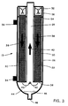
- Figure 3 is a schematic, vertical cross-sectional view along lines 3-3 in Figure 2 of a vaporizer for use in the system of Figure 1.
- FIG. 1 illustrates an overall system for producing preforms in which a vaporizer constructed in accordance with the present invention can be used.
- a reactant liquid such as OMCTS
- a gas such as oxygen
- the vaporizer produces a vapor/gas mixture which is provided to burners 20.
- the burners oxidize the reactant to produce silicon dioxide soot particles from which the desired preform is formed.
- a burner construction for use with OMCTS and similar materials is disclosed in WO-A-9 620 898 published 11 th July 1996.
- these burners are also supplied with an innershield gas, e.g., N 2 , an outershield gas, e.g., O 2 , and a mixture of CH 4 and oxygen to form a pilot flame.
- an innershield gas e.g., N 2
- an outershield gas e.g., O 2
- CH 4 and oxygen e.g., CH 4 and oxygen
- reactant liquid is stored in liquid feed tank 10, and is supplied to vaporizer 13 by liquid metering pump 12, which establishes a predetermined flow rate for the reactant, e.g., a flow rate in the range from 50 to 500 grams/minute for OMCTS, with a flow rate in the range from 200 to 400 grams/minute for OMCTS being preferred.
- the gas used in the vaporizer is stored in gas feed tank 14 and is transferred to the vaporizer at its own predetermined flow rate by gas mass flow controller 16.
- a preferred flow rate for the gas is in the range from about 0.2 to about 0.4 standard liters per minute (slpm) per gram/minute of OMCTS, with a flow rate of about 0.32 slpm per gram/minute of OMCTS being particularly preferred.
- This preferred gas flow rate provides an oxygen/OMCTS vapor mixture which can be directly supplied to burners 20 without the need for the addition of further oxygen to the mixture.
- preferred oxygen flow rates which provide ready-to-use oxygen/vapor mixtures, can be readily determined by persons skilled in the art.
- oxygen flow rates can be supplied to vaporizer 13 if desired. In such a case, additional oxygen will normally be added to the oxygen/vapor mixture downstream of vaporizer 13. Similarly, gases other than oxygen, e.g., an inert gas, such as nitrogen, can be supplied to vaporizer 13, and oxygen can be added to the inert gas/vapor mixture downstream of vaporizer 13.
- gases other than oxygen e.g., an inert gas, such as nitrogen
- Figures 2 and 3 show a preferred construction for vaporizer 13 employing a plurality of packed-bed columns 22 surrounding a central, vertically-oriented, vapor/gas receiving tube 24.
- the packed-bed columns and central tube 24 are preferably made of stainless steel, have a diameter of about 25 mm, and a length of about 75 cm. Other materials and component dimensions can, of course, be used if desired.
- packing materials can be used in the packed-bed columns, including beads, fibers, rings, saddles, and the like, which can be composed of glass, metal, ceramics, or other materials that are substantially inert to the reactant.
- a preferred packing material comprises ceramic elements having a saddle shape and a length of about 6 mm. This packing provides a large surface area to packed volume ratio.
- the bottom surface 56 of the packed-bed column is equipped with a grate, screen, or the like to retain the packing material within the column.
- the liquid phase (OMCTS) and the gas phase (O 2 ) are metered to a series of spray nozzles 32 located at the top of vaporizer 13 using liquid metering pump 12 and gas mass flow controller 16.
- Other means of supplying the liquid phase and the gas phase to the top of the packed-bed columns such as a manifold of tubes for each packed-bed column for distributing the liquid phase across the top surface of the column and a single tube for each column for the gas phase, can be used if desired, although the use of spray nozzles is preferred.
- Distribution of the liquid phase across the top surfaces 54 of the packed-bed columns is important since the liquid phase will tend to flow in a narrow stream through the column if supplied to only a portion of the top surface. Such a narrow stream will reduce the effective surface area available for evaporation of the liquid phase and thus reduce the efficiency of the vaporizer.
- Gas atomization nozzles which disperse the liquid phase into a cone of droplets carried by the gas phase (shown schematically at 58 in Figure 3) are particularly preferred. Such nozzles ensure uniform contact between the liquid and gas phases and uniform wetting of the bed packing. Nozzles of this type normally have separate inlets for the liquid phase and the gas phase. To ensure uniform operation of the plurality of packed-bed columns of Figures 2 and 3, the liquid phase inlets of the nozzles are connected to a liquid pressure equalizing manifold (not shown) and the gas inlets are connected to a gas pressure equalizing manifold (not shown). These manifolds, in turn, are connected to liquid metering pump 12 and gas mass flow controller 16, respectively.
- gas atomization nozzles having an orifice size of about 3 mm, a spray cone angle of about 60°, and a pressure drop across the nozzle of about 10 psig have been found to work successfully and are preferred.
- Other nozzles can be used in the practice of the invention if desired.
- Arrows 38, 40, and 42 in Figure 3 illustrate the flow pattern through vaporizer 13.
- Arrows 38 represent the concurrent downward flow of liquid reactant and gas through the packed-bed columns, with the liquid reactant becoming a vapor prior to reaching the bottom surfaces 56 of the columns (see below).
- Arrow 40 represents the upperward flow of the vapor/gas mixture through central tube 24, and arrows 42 represent the change in the direction of flow of the vapor/gas mixture from downward to upward in phase separator 44. As discussed below, this change in direction serves the important function of separating higher molecular weight species of the reactant (shown schematically in Figure 3 at 46) from the vapor/gas mixture.
- Hot oil 28 serves to heat packed-bed columns 22 by flowing around the outside walls 50 of the columns. It also serves to heat the vapor/gas mixture flowing in central tube 24 by heating the outside wall 52 of that tube. Heated fluids other than hot oil, e.g., steam, can be used to heat the packed-bed columns and the central tube, if desired. Also, other heating means, such as electrical heat tape can be used, although the heated fluid approach is preferred since it minimizes the chances for hot spots in the vaporizer which may lead to polymerization of the reactant.
- hot oil e.g., silicone oil
- Hot oil 28 enters vaporizer 13 through inlet port 34 and leaves the vaporizer through outlet port 36. While in the vaporizer, the hot oil flows through passages 30 defined by the vaporizer's outer shell 26 and the outside surfaces of the packed-bed columns and the central tube. Baffles (not shown) can be incorporated in passages 30 to ensure a uniform distribution of hot oil around the circumferences of walls 50 and 52.
- outer shell 26 extends above nozzles 32 (and above the pressure equalizing manifolds discussed above to which those nozzles are connected) so that the inside of the vaporizer is a closed space. Passing through the outer shell are oil ports 34 and 36, the outlet of central tube 24, and inlet ports (not shown) which provide liquid reactant and gas to the pressure equalizing manifolds.
- the mechanism of operation of vaporizer 13 can be viewed as being analogous to what takes place at the surface of a wet-bulb thermometer. That is, liquid reactant coats the surfaces of the packing material and the gas surrounds those surfaces. In the upper regions of the columns, the gas is unsaturated. Accordingly, the packing material functions as the bulb of the wet-bulb thermometer, with liquid reactant absorbing heat from the packing material and evaporating into the surrounding unsaturated gas.
- the gas and liquid phases are heated simultaneously as they pass downward through the packed-bed column. As their temperature increases, more liquid vaporizes into the gas phase.
- the process is controlled by the flow of heat and the diffusion of the vapor through the gas at the interface between the gas and the liquid. The process continues as the mixture flows downward through the columns until the dew point temperature is reached. At the dew point temperature, all of the liquid phase will have been converted into vapor, except for the undesirable higher molecular weight species of the reactant. Thereafter, the vapor/gas mixture continues to increase in temperature as it flows downward towards the column's bottom surface 56.
- the dew point temperature will depend upon the mole ratios of the reactant and the gas, the pressure within the packed-bed column, and the specific reactant which is to be vaporized. For example, for the OMCTS and oxygen flow rates set forth above and a maximum pressure (P max ) within column 22 of about 137.9 kPa (20 psig), the dew point temperature for OMCTS is in the range of about 145-150°C.
- the temperature of hot oil 28 is set at a value that will ensure that the liquid reactant and the gas will be heated to a temperature above the dew point temperature before they reach the bottom surface 56 of the column.
- an oil temperature of 175°C has been found sufficient to satisfy this requirement for OMCTS as the reactant and for the OMCTS and O 2 flow rates given above.
- Other temperatures can be used if desired.
- the amount of heating needed for other reactants, other mole ratios, other P max values, and other vaporizer dimensions can be readily determined by persons skilled in the art from the disclosure herein.
- phase separator 44 At the exit of the packed columns is phase separator 44 in which higher molecular weight impurities 46 are separated from the vapor/gas mixture and collected for waste discharge.
- separator 44 includes port 48 for removing the higher molecular weight species during, for example, periodic maintenance of the system.
- phase separator 44 comprises a chamber which causes the flow of the vapor/gas mixture to change from downward to upward. This change in direction effectively removes undesirable gels and gums from the vapor/gas stream.
- Other approaches for cleaning the vapor/gas stream include turning the stream through an angle of less than 180°, e.g., by 90°, and placing an impingement plate and/or filtration material such as glass wool, in the region of the stream which carries the impurities after the turn has been negotiated, i.e., in the outer portions of the stream as seen from the center of the turn.
- the stream exiting the packed columns can be filtered without a change in direction if desired.
- phase separator 44 After leaving phase separator 44, the clean vapor/gas mixture travels upward through central tube 24.
- the wall of tube 24 is heated by hot oil 28 and thus the temperature of the vapor/gas mixture is maintained as it passes through the tube and out of the vaporizer.
- a single tube packed-bed column was constructed using the saddle-shaped ceramic packing material described above.
- the column was made of stainless steel and had the dimensions described above. Its outer surface was heated to approximately 175°C using heat tape.
- OMCTS and oxygen were supplied to a gas atomization nozzle of the type described above at an inlet pressure of approximately 206.8 kPa (30 psig).
- the pressure drop across the nozzle was approximately 68.9 kPa (10 psig), and the pressure at the exit of the column was approximately one atmosphere.
- OMCTS flow rates in the range from 33 to 67 grams/minute were used, with the oxygen flow rate fixed at a ratio of 0.32 slpm/(g/min) liquid. For example, when the liquid flow rate was set at 33 g/min, the corresponding gas flow rate was 10.6 slpm.
- These OMCTS flow rates are equivalent to flow rates in the 200 to 400 grams/minute range for a vaporizer having six packed-bed columns as shown in Figures 2 and 3. Both the gas and liquid phases entered the spray nozzle at room temperature (25°C). Table 1 summarizes the measured vapor temperature at the bottom of the column for the two flow rate extremes.
- the dew point temperature for OMCTS under these test conditions is approximately 120-125°C.
- the packed-bed column was able to raise the temperature of the reactant and the gas to well over this temperature for a wide range of flow rates. Consistent with these temperatures, no liquid reactant was observed exiting the bottom of column.
Landscapes
- Chemical & Material Sciences (AREA)
- Engineering & Computer Science (AREA)
- Chemical Kinetics & Catalysis (AREA)
- Organic Chemistry (AREA)
- Materials Engineering (AREA)
- General Chemical & Material Sciences (AREA)
- Mechanical Engineering (AREA)
- Metallurgy (AREA)
- Manufacturing & Machinery (AREA)
- General Life Sciences & Earth Sciences (AREA)
- Life Sciences & Earth Sciences (AREA)
- Geochemistry & Mineralogy (AREA)
- Inorganic Chemistry (AREA)
- Feeding, Discharge, Calcimining, Fusing, And Gas-Generation Devices (AREA)
- Glass Melting And Manufacturing (AREA)
- Chemical Vapour Deposition (AREA)
- Manufacture, Treatment Of Glass Fibers (AREA)
Abstract
Claims (15)
- Un appareil pour vaporiser un liquide réactif utilisé dans la formation d'une préforme contenant du dioxyde de silicium, ledit réactif étant polymérisable pour former des espèces chimiques de poids moléculaire plus élevé, ledit appareil comprenant :une colonne à garnissage tassé (22) à orientation verticale présentant une surface sommitale (54) et une surface de fond (56) et ayant une pression intérieure de fonctionnement dont la valeur maximum est Pmax ;un moyen d'introduction (10, 12, 14, 16, 32) pour :(a) introduire le réactif liquide dans la colonne à garnissage tassé sous un premier débit d'écoulement prédéterminé et pour répartir le réactif liquide sur l'aire de section droite de la colonne, et(b) introduire un gaz dans la colonne à garnissage tassé dans la région de la surface sommitale de la colonne sous un deuxième débit d'écoulement prédéterminé,de sorte que le réactif liquide et le gaz traversent tous deux la colonne à garnissage tassé dans le sens descendant ;un moyen de chauffage (18, 28, 30, 34, 36, 60, 62) pour chauffer la colonne à garnissage tassé à une température suffisamment élevée pour que, avant d'atteindre la surface de fond de la colonne à garnissage tassé, le réactif liquide et le gaz sous leurs débits d'écoulement prédéterminés se trouvent chauffés à une température supérieure au point de rosée du réactif liquide à la pression Pmax, d'où s'ensuit que le réactif liquide se trouve vaporisé avant d'atteindre la surface de fond et quitte cette surface sous la forme d'un mélange du réactif vaporisé et du gaz, dit mélange vapeur/gaz ;un moyen de réception (24) pour recevoir le mélange vapeur/gaz quittant la surface de fond de la colonne à garnissage tassé ;un moyen de séparation (44) disposé entre la surface de fond de la colonne à garnissage tassé et le moyen de réception pour séparer du mélange vapeur/gaz des espèces chimiques de poids moléculaire plus élevé (46) du réactif ; etun moyen d'évacuation (48) pour évacuer du moyen de séparation (44) des espèces chimiques de poids moléculaire plus élevé du réactif.
- Un appareil selon la revendication 1 dans lequel le moyen d'introduction (10, 12, 14, 16, 32) comprend une buse de pulvérisation de gaz (58) pour pulvériser un mélange du réactif liquide et du gaz sur la surface sommitale (54) de la colonne à garnissage tassé (22).
- Un appareil selon la revendication 1 ou 2 dans lequel le moyen de chauffage comprend un moyen (30, 34, 36) pour envoyer un fluide chauffé (28) le long d'au moins une portion de la surface extérieure de la colonne à garnissage tassé (22).
- Un appareil selon l'une quelconque des revendications 1 à 3, comprenant en outre des moyens (18, 28) pour chauffer le moyen de réception (24).
- Un appareil selon l'une quelconque des revendications 1 à 4 dans lequel le moyen de réception (24) comprend un conduit (24) orienté verticalement.
- Un appareil selon la revendication 5 comprenant en outre des moyens (18, 34, 36) pour envoyer un fluide chauffé (28) le long d'au moins une portion (30) de la surface extérieure (50) du conduit orienté verticalement.
- Un appareil selon la revendication 5 ou 6 dans lequel le moyen de séparation (44) comprend un conduit que relie la colonne à garnissage tassé (22) au conduit orienté verticalement (24) et à l'intérieur duquel le sens d'écoulement du mélange vapeur/gaz passe du sens descendant (38) au sens ascendant (40) .
- Un appareil selon l'une quelconque des revendications 1 à 7 adapté à la production d'une préforme convenant à la production d'une fibre de guide d'ondes optique.
- Un appareil selon la revendication 1 comprenant :une multiplicité de colonnes à garnissage tassé (22) d'orientation verticale, chaque colonne présentant une surface sommitale (54) et une surface de fond (56) et ayant une pression intérieure de fonctionnement dont la valeur maximum pour toutes les colonnes est Pmax ;un moyen d'introduction (10, 12, 14, 16, 32) pour :(a) introduire le réactif liquide dans chacune des colonnes à garnissage tassé sous un premier débit d'écoulement prédéterminé et pour répartir le réactif liquide sur l'aire de section droite de chacune des colonnes, et(b) introduire un gaz dans chacune des colonnes à garnissage tassé dans la région de la surface sommitale de la colonne sous un deuxième débit d'écoulement prédéterminé,de sorte que le réactif liquide et le gaz traversent tous deux chacune des colonnes à garnissage tassé dans le sens descendant;un moyen de chauffage (18, 28, 30, 34, 36, 60, 62) pour chauffer chacune des colonnes à garnissage tassé à une température suffisamment élevée pour que, avant d'atteindre la surface de fond de la colonne, le réactif liquide et le gaz sous leurs débits d'écoulement prédéterminés se trouvent chauffés à une température supérieure au point de rosée du réactif liquide à la pression Pmax, d'où s'ensuit que le réactif liquide se trouve vaporisé avant d'avoir atteint la surface de fond et quitte cette surface sous la forme d'un mélange du réactif vaporisé et du gaz, dit mélange vapeur/gaz ;un moyen de réception (24) pour recevoir le mélange vapeur/gaz quittant la surface de fond des colonnes à garnissage tassé ;un moyen de séparation (44) entre les surfaces de fond des colonnes à garnissage tassé et le moyen de réception pour séparer du mélange vapeur/gaz des espèces chimiques de poids moléculaire plus élevé (46) du réactif ; etun moyen d'évacuation (48) pour évacuer du moyen de séparation (44) des espèces chimiques de poids moléculaire plus élevé du réactif.
- Un procédé pour fournir des vapeurs réactives pour réaliser une préforme contenant du dioxyde de silicium par décomposition desdites vapeurs réactives pour former des particules, comprenant les opérations consistant :(a) à prendre un réactif sous forme liquide sous un premier débit d'écoulement prédéterminé, ledit réactif étant polymérisable pour former des espèces chimiques de poids moléculaire plus élevé ;(b) à prendre un gaz sous un deuxième débit d'écoulement prédéterminé ;(c) à prendre une colonne à garnissage tassé (22) orientée verticalement et présentant une surface sommitale (54) et une surface de fond (56) ;(d) à envoyer le réactif liquide et le gaz à travers la colonne à garnissage tassé (22) de manière que le réactif liquide et le gaz circulent tous deux dans le sens descendant à l'intérieur de la colonne, la pression intérieure de fonctionnement maximum à l'intérieur de la colonne pendant cette circulation descendante étant Pmax ;(e) à chauffer la colonne à garnissage tassé (22) à une température suffisamment élevée pour que, avant d'atteindre la surface de fond (56) de la colonne, le réactif liquide et le gaz sous leurs débits d'écoulement prédéterminés se trouvent chauffés à une température supérieure au point de rosée du réactif liquide à la pression Pmax, d'où s'ensuit que le réactif liquide se trouve vaporisé avant d'avoir atteint la surface de fond et quitte cette surface sous la forme d'un mélange du réactif vaporisé et du gaz (mélange vapeur/gaz ;(f) à séparer du mélange vapeur/gaz des espèces chimiques de poids moléculaire plus élevé du réactif ; et(g) à délivrer le mélange vapeur/gaz à un site d'utilisation de vapeur (20) pour former ladite préforme.
- Un procédé selon la revendication 10 dans lequel, à l'opération (f), les espèces de poids moléculaire plus élevé (46) sont séparées du mélange vapeur/gaz en faisant passer le sens (42) d'écoulement du mélange vapeur/gaz du sens descendant (38) au sens ascendant (40).
- Un procédé selon la revendication 10 ou 11 dans lequel le réactif est un polyméthylsiloxane.
- Un procédé selon la revendication 12 dans lequel le réactif est de l'octaméthylcyclotétrasiloxane.
- Un procédé selon l'une quelconque des revendications 10 à 13 dans lequel le gaz est de l'oxygène.
- Un procédé selon l'une quelconque des revendications 10 à 14 dans lequel la préforme est utilisée pour produire une fibre de guide d'ondes optique.
Applications Claiming Priority (3)
| Application Number | Priority Date | Filing Date | Title |
|---|---|---|---|
| US08/368,319 US5558687A (en) | 1994-12-30 | 1994-12-30 | Vertical, packed-bed, film evaporator for halide-free, silicon-containing compounds |
| US368319 | 1994-12-30 | ||
| PCT/US1995/016737 WO1996020897A1 (fr) | 1994-12-30 | 1995-12-19 | Evaporateur pelliculaire vertical, a lit fixe, pour composes depourvus d'halogenure et contenant du silicium |
Publications (2)
| Publication Number | Publication Date |
|---|---|
| EP0800489A1 EP0800489A1 (fr) | 1997-10-15 |
| EP0800489B1 true EP0800489B1 (fr) | 1999-08-04 |
Family
ID=23450739
Family Applications (1)
| Application Number | Title | Priority Date | Filing Date |
|---|---|---|---|
| EP95944370A Expired - Lifetime EP0800489B1 (fr) | 1994-12-30 | 1995-12-19 | Evaporateur pelliculaire vertical, a lit fixe, pour composes depourvus d'halogenure et contenant du silicium |
Country Status (7)
| Country | Link |
|---|---|
| US (2) | US5558687A (fr) |
| EP (1) | EP0800489B1 (fr) |
| JP (1) | JPH10511923A (fr) |
| AU (1) | AU705116B2 (fr) |
| CA (1) | CA2208031A1 (fr) |
| DE (1) | DE69511288T2 (fr) |
| WO (1) | WO1996020897A1 (fr) |
Families Citing this family (60)
| Publication number | Priority date | Publication date | Assignee | Title |
|---|---|---|---|---|
| EP1007484A4 (fr) * | 1997-07-21 | 2000-09-20 | Corning Inc | Procede et dispositif permettant de produire des vapeurs de charge d'alimentation de faible debit |
| KR100574123B1 (ko) * | 1997-09-24 | 2006-04-25 | 코닝 인코포레이티드 | 용융 실리카-티타니아 유리의 제조방법 |
| US6086711A (en) * | 1997-10-06 | 2000-07-11 | Nisene Technology Group | Vapor generation system and process |
| US6094940A (en) * | 1997-10-09 | 2000-08-01 | Nikon Corporation | Manufacturing method of synthetic silica glass |
| US6161398A (en) * | 1998-04-09 | 2000-12-19 | Lucent Technologies, Inc. | Methods of and systems for vapor delivery control in optical preform manufacture |
| US6336347B1 (en) | 1998-12-28 | 2002-01-08 | Pirelli Cavi E Sistemi S.P.A. | Process for producing silica by decomposition of an organosilane |
| FR2800754B1 (fr) | 1999-11-08 | 2003-05-09 | Joint Industrial Processors For Electronics | Dispositif evaporateur d'une installation de depot chimique en phase vapeur |
| DE19960333C2 (de) * | 1999-12-15 | 2002-12-19 | Tetra Laval Holdings & Finance | Vorrichtung zum Herstellen eines Gasgemisches und deren Verwendung |
| US6418756B1 (en) | 2000-01-28 | 2002-07-16 | Corning Incorporated | Method of making planar waveguides using low flow rates of feedstock vapors from a gas and liquid mixture |
| JP2004509041A (ja) * | 2000-05-25 | 2004-03-25 | コーニング インコーポレイテッド | チタニアドープ石英ガラスプリフォームの作成方法 |
| FR2815336B1 (fr) * | 2000-10-16 | 2002-12-13 | Didier Costes | Appareil de dessalement d'eau utilisant un cycle a air humide |
| ATE370105T1 (de) * | 2002-06-28 | 2007-09-15 | Prysmian Cavi Sistemi Energia | Verfahren und vorrichtung zum verdampfen eines flüssigen vorlaüfers beim herstellen einer glasvorform |
| US7785448B2 (en) * | 2002-08-07 | 2010-08-31 | Deka Products Limited Partnership | Method and apparatus for phase change enhancement |
| US20040074757A1 (en) * | 2002-08-07 | 2004-04-22 | Kingston Owens | Method and apparatus for phase change enhancement |
| US8511105B2 (en) | 2002-11-13 | 2013-08-20 | Deka Products Limited Partnership | Water vending apparatus |
| US7340879B2 (en) | 2002-11-13 | 2008-03-11 | Deka Products Limited Partnership | Locally powered water distillation system |
| US7597784B2 (en) * | 2002-11-13 | 2009-10-06 | Deka Products Limited Partnership | Pressurized vapor cycle liquid distillation |
| US11260316B2 (en) * | 2002-11-13 | 2022-03-01 | Deka Products Limited Partnership | Pressurized vapor cycle liquid distillation |
| US8069676B2 (en) | 2002-11-13 | 2011-12-06 | Deka Products Limited Partnership | Water vapor distillation apparatus, method and system |
| US7225620B2 (en) * | 2002-12-17 | 2007-06-05 | University Of Florida Research Foundation, Inc. | Diffusion driven water purification apparatus and process |
| US6919000B2 (en) * | 2002-12-17 | 2005-07-19 | University Of Florida | Diffusion driven desalination apparatus and process |
| US7547363B2 (en) * | 2003-07-08 | 2009-06-16 | Tosoh Finechem Corporation | Solid organometallic compound-filled container and filling method thereof |
| US20050205215A1 (en) * | 2004-03-17 | 2005-09-22 | General Electric Company | Apparatus for the evaporation of aqueous organic liquids and the production of powder pre-forms in flame hydrolysis processes |
| US8603580B2 (en) * | 2005-11-28 | 2013-12-10 | Msp Corporation | High stability and high capacity precursor vapor generation for thin film deposition |
| US11826681B2 (en) | 2006-06-30 | 2023-11-28 | Deka Products Limited Partneship | Water vapor distillation apparatus, method and system |
| DE102006036462A1 (de) * | 2006-08-04 | 2008-02-07 | Sig Technology Ag | Verdampfer für Sterilisationsmittel zur Sterilisation von Füllmaschinen und/oder Packungen |
| JP5148367B2 (ja) * | 2007-05-29 | 2013-02-20 | 信越化学工業株式会社 | 高周波誘導熱プラズマトーチを用いた光ファイバプリフォームの製造方法 |
| US8006511B2 (en) | 2007-06-07 | 2011-08-30 | Deka Products Limited Partnership | Water vapor distillation apparatus, method and system |
| US11884555B2 (en) | 2007-06-07 | 2024-01-30 | Deka Products Limited Partnership | Water vapor distillation apparatus, method and system |
| SI2500261T1 (sl) | 2007-08-09 | 2017-09-29 | Lta Corporation | Lečasto zračno plovilo in povezane kontrole |
| US8894002B2 (en) | 2010-07-20 | 2014-11-25 | Lta Corporation | System and method for solar-powered airship |
| US8359877B2 (en) | 2008-08-15 | 2013-01-29 | Deka Products Limited Partnership | Water vending apparatus |
| WO2011026483A2 (fr) | 2009-09-02 | 2011-03-10 | Invensor Gmbh | Amenée et distribution de réfrigérant sur une surface d'un échangeur de chaleur équipant des machines à sorption |
| US8495973B2 (en) * | 2009-11-03 | 2013-07-30 | Protonex Technology Corporation | Thin film vaporizer |
| GB201019920D0 (en) | 2010-11-24 | 2011-01-05 | Doosan Power Systems Ltd | Column |
| GB201019919D0 (en) * | 2010-11-24 | 2011-01-05 | Doosan Power Systems Ltd | Column |
| US8747530B2 (en) | 2011-02-15 | 2014-06-10 | Lta Corporation | Systems for water extraction from air |
| US8840858B2 (en) | 2011-07-06 | 2014-09-23 | Corning Incorporated | Apparatus for mixing vaporized precursor and gas and method therefor |
| JP6559423B2 (ja) | 2011-08-05 | 2019-08-14 | スリーエム イノベイティブ プロパティズ カンパニー | 蒸気を処理するためのシステム及び方法 |
| DE102011119374A1 (de) * | 2011-11-25 | 2013-05-29 | Heraeus Quarzglas Gmbh & Co. Kg | Verfahren zur Herstellung von synthetischem Quarzglas |
| DE102011119373A1 (de) * | 2011-11-25 | 2013-05-29 | Heraeus Quarzglas Gmbh & Co. Kg | Verfahren zur Herstellung von synthetischem Quarzglas |
| DE102011121190A1 (de) * | 2011-12-16 | 2013-06-20 | Heraeus Quarzglas Gmbh & Co. Kg | OMCTS-Verdampfungsverfahren |
| WO2014018896A1 (fr) | 2012-07-27 | 2014-01-30 | Deka Products Limited Partnership | Commande de la conductivité dans une sortie d'eau de production destinée à un évaporateur |
| AU2014377667A1 (en) | 2013-11-04 | 2016-05-19 | Lta Corporation | Cargo airship |
| FR3018200B1 (fr) * | 2014-03-10 | 2017-12-01 | Ifp Energies Now | Contacteur pour colonne d'echange constitue de compartiments de garnissage vrac |
| EP3034476A1 (fr) | 2014-12-16 | 2016-06-22 | Heraeus Quarzglas GmbH & Co. KG | Procédé de fabrication de verre de quartz synthétique à l'aide d'un dispositif de purification |
| EP3059212A1 (fr) | 2015-02-18 | 2016-08-24 | Heraeus Quarzglas GmbH & Co. KG | Procédé et dispositif de fabrication de verre de silice à partir de polyalkaylsiloxane polymérisable avec un filtre membrane comme dispositif de purification |
| WO2017003791A1 (fr) | 2015-06-30 | 2017-01-05 | 3M Innovative Properties Company | Revêtements discontinus et leurs procédés de formation |
| JP2019513189A (ja) | 2016-04-01 | 2019-05-23 | スリーエム イノベイティブ プロパティズ カンパニー | ロールツーロール原子層堆積装置及び方法 |
| JP6650820B2 (ja) | 2016-04-19 | 2020-02-19 | 株式会社フジクラ | ガラスインゴットの製造方法 |
| CN107010823A (zh) * | 2017-05-18 | 2017-08-04 | 长飞光纤潜江有限公司 | 一种用于光纤预制棒外部沉积的omcts蒸发装置 |
| KR102014913B1 (ko) * | 2017-11-08 | 2019-08-27 | 주식회사 에스티아이 | 광섬유 모재 증착 시스템 |
| EP3643375A1 (fr) * | 2018-10-24 | 2020-04-29 | Linde Aktiengesellschaft | Colonne et installation de séparation ainsi que procédé de traitement séparatif d'un fluide ou d'une pluralité de fluides |
| JP6901153B2 (ja) | 2019-02-07 | 2021-07-14 | 株式会社高純度化学研究所 | 薄膜形成用金属ハロゲン化合物の固体気化供給システム。 |
| JP6887688B2 (ja) * | 2019-02-07 | 2021-06-16 | 株式会社高純度化学研究所 | 蒸発原料用容器、及びその蒸発原料用容器を用いた固体気化供給システム |
| CN113439074A (zh) | 2019-02-13 | 2021-09-24 | 康宁股份有限公司 | 蒸发器及包含该蒸发器的用于形成玻璃光纤预制件的设备 |
| CN110613943B (zh) * | 2019-10-22 | 2024-04-26 | 无锡华立聚能装备有限公司 | 自过滤蒸发器系统 |
| CN112028466B (zh) * | 2020-09-01 | 2021-08-31 | 长飞光纤光缆股份有限公司 | 一种用于制备光纤预制棒的有机硅原料蒸发装置 |
| JP7449842B2 (ja) * | 2020-11-02 | 2024-03-14 | 信越化学工業株式会社 | 多孔質ガラス母材の製造方法及び製造装置 |
| US12577663B2 (en) * | 2021-06-28 | 2026-03-17 | Applied Materials, Inc. | Ampoule for a semiconductor manufacturing precursor |
Family Cites Families (28)
| Publication number | Priority date | Publication date | Assignee | Title |
|---|---|---|---|---|
| US2087156A (en) * | 1937-02-15 | 1937-07-13 | Liggett Thomas | Gas absorption tower |
| US2849430A (en) * | 1955-07-07 | 1958-08-26 | Dow Chemical Co | Removal of volatile ingredients from thermoplastic polymers |
| US2893359A (en) * | 1957-01-28 | 1959-07-07 | Shell Dev | Apparatus for vaporizing liquids |
| US3191662A (en) * | 1962-07-18 | 1965-06-29 | Kenneth J Schneider | Continuous solution concentrator |
| US3316064A (en) * | 1964-04-30 | 1967-04-25 | Hitachi Ltd | Apparatus for continuous polycondensation reaction |
| US3298797A (en) * | 1965-11-29 | 1967-01-17 | Hooker Chemical Corp | Alkali metal hydroxide evaporation |
| US4185075A (en) * | 1967-11-20 | 1980-01-22 | Occidental Research and Engineering Ltd. | Phosphoric acid ammoniation apparatus with water quench |
| US4104112A (en) * | 1973-10-17 | 1978-08-01 | Niagara Blower Company | Method and apparatus for concentrating aqueous solutions |
| US3895994A (en) * | 1974-02-15 | 1975-07-22 | Kenji Saguchi | Spray dryer |
| GB1559978A (en) * | 1976-12-01 | 1980-01-30 | Gen Electric Co Ltd | Chemical vapour deposition processes |
| US4529427A (en) * | 1977-05-19 | 1985-07-16 | At&T Bell Laboratories | Method for making low-loss optical waveguides on an industrial scale |
| US4212663A (en) * | 1978-01-26 | 1980-07-15 | Corning Glass Works | Reactants delivery system for optical waveguide manufacturing |
| US4166730A (en) * | 1978-05-25 | 1979-09-04 | Warhol John G | Scrubber |
| US4314837A (en) * | 1979-03-01 | 1982-02-09 | Corning Glass Works | Reactant delivery system method |
| US4325987A (en) * | 1979-07-31 | 1982-04-20 | Societa Italiana Vetro-Siv-S.P.A. | Process for the production of an electrically conducting article |
| JPS58125633A (ja) * | 1982-01-18 | 1983-07-26 | Nippon Telegr & Teleph Corp <Ntt> | ガラス微粒子製造におけるガス供給方法 |
| US4476065A (en) * | 1983-04-20 | 1984-10-09 | Niagara Blower Co. | Increased capacity wet surface air cooling system |
| JPS61254242A (ja) * | 1985-05-01 | 1986-11-12 | Sumitomo Electric Ind Ltd | 原料供給装置 |
| US4600654A (en) * | 1985-05-14 | 1986-07-15 | M&T Chemicals Inc. | Method of producing transparent, haze-free tin oxide coatings |
| US4924936A (en) * | 1987-08-05 | 1990-05-15 | M&T Chemicals Inc. | Multiple, parallel packed column vaporizer |
| US5090985A (en) * | 1989-10-17 | 1992-02-25 | Libbey-Owens-Ford Co. | Method for preparing vaporized reactants for chemical vapor deposition |
| US4924636A (en) * | 1989-10-20 | 1990-05-15 | National-Detroit, Inc. | Orbital rubbing machine with improved spindle locking member |
| US5078092A (en) * | 1989-12-22 | 1992-01-07 | Corning Incorporated | Flash vaporizer system for use in manufacturing optical waveguide fiber |
| US5043002A (en) * | 1990-08-16 | 1991-08-27 | Corning Incorporated | Method of making fused silica by decomposing siloxanes |
| FR2673041A1 (fr) * | 1991-02-19 | 1992-08-21 | Gemplus Card Int | Procede de fabrication de micromodules de circuit integre et micromodule correspondant. |
| US5349829A (en) * | 1992-05-21 | 1994-09-27 | Aoc, Inc. | Method and apparatus for evaporatively cooling gases and/or fluids |
| NL9201854A (nl) * | 1992-10-26 | 1994-05-16 | Franciscus Petrus Maria Nooren | Werkwijze en inrichting voor het zuiveren van vloeibaar materiaal, in het bijzonder polysiloxaan alsmede toepassing van het gezuiverde vloeibare materiaal. |
| US5356451A (en) * | 1993-12-20 | 1994-10-18 | Corning Incorporated | Method and apparatus for vaporization of liquid reactants |
-
1994
- 1994-12-30 US US08/368,319 patent/US5558687A/en not_active Expired - Fee Related
-
1995
- 1995-12-19 DE DE69511288T patent/DE69511288T2/de not_active Expired - Fee Related
- 1995-12-19 EP EP95944370A patent/EP0800489B1/fr not_active Expired - Lifetime
- 1995-12-19 JP JP8521095A patent/JPH10511923A/ja not_active Ceased
- 1995-12-19 AU AU46438/96A patent/AU705116B2/en not_active Ceased
- 1995-12-19 CA CA002208031A patent/CA2208031A1/fr not_active Abandoned
- 1995-12-19 WO PCT/US1995/016737 patent/WO1996020897A1/fr not_active Ceased
- 1995-12-22 US US08/577,985 patent/US5707415A/en not_active Expired - Fee Related
Also Published As
| Publication number | Publication date |
|---|---|
| EP0800489A1 (fr) | 1997-10-15 |
| JPH10511923A (ja) | 1998-11-17 |
| US5707415A (en) | 1998-01-13 |
| CA2208031A1 (fr) | 1996-07-11 |
| DE69511288T2 (de) | 2000-02-24 |
| WO1996020897A1 (fr) | 1996-07-11 |
| AU4643896A (en) | 1996-07-24 |
| AU705116B2 (en) | 1999-05-13 |
| DE69511288D1 (de) | 1999-09-09 |
| US5558687A (en) | 1996-09-24 |
Similar Documents
| Publication | Publication Date | Title |
|---|---|---|
| US5707415A (en) | Method of vaporizing reactants in a packed-bed, column, film evaporator | |
| EP0719575B1 (fr) | Procédé de vaporisation des composés siliciques exempt de halogénure | |
| CN105283425B (zh) | 用于制造合成石英玻璃的蒸发器和方法 | |
| CN1152079C (zh) | 纯化聚烷基硅氧烷的方法及所得产物 | |
| KR100312009B1 (ko) | 폐개스의정화를위한방법과장치 | |
| US6837076B2 (en) | Method of producing oxide soot using a burner with a planar burner face | |
| JP6013500B2 (ja) | 合成石英ガラスを製造する方法及び光ファイバーを製造する方法 | |
| JPH04110462A (ja) | フラッシュ蒸発装置、フラッシュ蒸発器およびフラッシュ蒸発器によってプリフォームを形成する方法 | |
| JP2015504408A (ja) | スート法に従って合成石英ガラスを製造する方法 | |
| US7730747B2 (en) | Method for vaporizing a liquid reactant in manufacturing a glass preform | |
| US4642129A (en) | Method for manufacturing preforms of glass for optical fibers | |
| US10513454B2 (en) | Method and apparatus for producing fused quartz from a polymerizable polyalkylsiloxane compound with membrane filter as cleaning device | |
| EP0975690B1 (fr) | Processus de purification de siloxane | |
| EP0610930B1 (fr) | Procédé pour la fabrication d'une préforme de verre pour fibres optiques et dispositif pour le procédé | |
| CN112028466B (zh) | 一种用于制备光纤预制棒的有机硅原料蒸发装置 | |
| WO2001092172A1 (fr) | Procede de fabrication d'une preforme en verre de silice dopee au dioxyde de titane | |
| KR20030069187A (ko) | 레이아웃 동안 실리카를 불소로 도핑하는 장치 및 그 방법 | |
| JPS6221735B2 (fr) |
Legal Events
| Date | Code | Title | Description |
|---|---|---|---|
| PUAI | Public reference made under article 153(3) epc to a published international application that has entered the european phase |
Free format text: ORIGINAL CODE: 0009012 |
|
| 17P | Request for examination filed |
Effective date: 19970702 |
|
| AK | Designated contracting states |
Kind code of ref document: A1 Designated state(s): DE FR GB IT NL |
|
| 17Q | First examination report despatched |
Effective date: 19971007 |
|
| GRAG | Despatch of communication of intention to grant |
Free format text: ORIGINAL CODE: EPIDOS AGRA |
|
| GRAG | Despatch of communication of intention to grant |
Free format text: ORIGINAL CODE: EPIDOS AGRA |
|
| GRAG | Despatch of communication of intention to grant |
Free format text: ORIGINAL CODE: EPIDOS AGRA |
|
| GRAH | Despatch of communication of intention to grant a patent |
Free format text: ORIGINAL CODE: EPIDOS IGRA |
|
| GRAH | Despatch of communication of intention to grant a patent |
Free format text: ORIGINAL CODE: EPIDOS IGRA |
|
| GRAA | (expected) grant |
Free format text: ORIGINAL CODE: 0009210 |
|
| AK | Designated contracting states |
Kind code of ref document: B1 Designated state(s): DE FR GB IT NL |
|
| REF | Corresponds to: |
Ref document number: 69511288 Country of ref document: DE Date of ref document: 19990909 |
|
| ITF | It: translation for a ep patent filed | ||
| ET | Fr: translation filed | ||
| PLBE | No opposition filed within time limit |
Free format text: ORIGINAL CODE: 0009261 |
|
| STAA | Information on the status of an ep patent application or granted ep patent |
Free format text: STATUS: NO OPPOSITION FILED WITHIN TIME LIMIT |
|
| 26N | No opposition filed | ||
| PGFP | Annual fee paid to national office [announced via postgrant information from national office to epo] |
Ref country code: NL Payment date: 20010921 Year of fee payment: 7 |
|
| REG | Reference to a national code |
Ref country code: GB Ref legal event code: IF02 |
|
| PGFP | Annual fee paid to national office [announced via postgrant information from national office to epo] |
Ref country code: DE Payment date: 20021031 Year of fee payment: 8 |
|
| PGFP | Annual fee paid to national office [announced via postgrant information from national office to epo] |
Ref country code: GB Payment date: 20021104 Year of fee payment: 8 |
|
| PGFP | Annual fee paid to national office [announced via postgrant information from national office to epo] |
Ref country code: FR Payment date: 20021202 Year of fee payment: 8 |
|
| PG25 | Lapsed in a contracting state [announced via postgrant information from national office to epo] |
Ref country code: NL Free format text: LAPSE BECAUSE OF NON-PAYMENT OF DUE FEES Effective date: 20030701 |
|
| NLV4 | Nl: lapsed or anulled due to non-payment of the annual fee |
Effective date: 20030701 |
|
| PG25 | Lapsed in a contracting state [announced via postgrant information from national office to epo] |
Ref country code: GB Free format text: LAPSE BECAUSE OF NON-PAYMENT OF DUE FEES Effective date: 20031219 |
|
| PG25 | Lapsed in a contracting state [announced via postgrant information from national office to epo] |
Ref country code: DE Free format text: LAPSE BECAUSE OF NON-PAYMENT OF DUE FEES Effective date: 20040701 |
|
| GBPC | Gb: european patent ceased through non-payment of renewal fee |
Effective date: 20031219 |
|
| PG25 | Lapsed in a contracting state [announced via postgrant information from national office to epo] |
Ref country code: FR Free format text: LAPSE BECAUSE OF NON-PAYMENT OF DUE FEES Effective date: 20040831 |
|
| REG | Reference to a national code |
Ref country code: FR Ref legal event code: ST |
|
| PG25 | Lapsed in a contracting state [announced via postgrant information from national office to epo] |
Ref country code: IT Free format text: LAPSE BECAUSE OF NON-PAYMENT OF DUE FEES;WARNING: LAPSES OF ITALIAN PATENTS WITH EFFECTIVE DATE BEFORE 2007 MAY HAVE OCCURRED AT ANY TIME BEFORE 2007. THE CORRECT EFFECTIVE DATE MAY BE DIFFERENT FROM THE ONE RECORDED. Effective date: 20051219 |