EP0800638B1 - Verfahren und vorrichtung zur kühlung eines raumes - Google Patents
Verfahren und vorrichtung zur kühlung eines raumes Download PDFInfo
- Publication number
- EP0800638B1 EP0800638B1 EP96934299A EP96934299A EP0800638B1 EP 0800638 B1 EP0800638 B1 EP 0800638B1 EP 96934299 A EP96934299 A EP 96934299A EP 96934299 A EP96934299 A EP 96934299A EP 0800638 B1 EP0800638 B1 EP 0800638B1
- Authority
- EP
- European Patent Office
- Prior art keywords
- cooling
- cooling element
- room
- condensate
- during
- Prior art date
- Legal status (The legal status is an assumption and is not a legal conclusion. Google has not performed a legal analysis and makes no representation as to the accuracy of the status listed.)
- Expired - Lifetime
Links
Images

Classifications
-
- F—MECHANICAL ENGINEERING; LIGHTING; HEATING; WEAPONS; BLASTING
- F24—HEATING; RANGES; VENTILATING
- F24F—AIR-CONDITIONING; AIR-HUMIDIFICATION; VENTILATION; USE OF AIR CURRENTS FOR SCREENING
- F24F5/00—Air-conditioning systems or apparatus not covered by F24F1/00 or F24F3/00, e.g. using solar heat or combined with household units such as an oven or water heater
- F24F5/0089—Systems using radiation from walls or panels
- F24F5/0092—Systems using radiation from walls or panels ceilings, e.g. cool ceilings
-
- F—MECHANICAL ENGINEERING; LIGHTING; HEATING; WEAPONS; BLASTING
- F24—HEATING; RANGES; VENTILATING
- F24F—AIR-CONDITIONING; AIR-HUMIDIFICATION; VENTILATION; USE OF AIR CURRENTS FOR SCREENING
- F24F5/00—Air-conditioning systems or apparatus not covered by F24F1/00 or F24F3/00, e.g. using solar heat or combined with household units such as an oven or water heater
- F24F5/0089—Systems using radiation from walls or panels
-
- F—MECHANICAL ENGINEERING; LIGHTING; HEATING; WEAPONS; BLASTING
- F24—HEATING; RANGES; VENTILATING
- F24F—AIR-CONDITIONING; AIR-HUMIDIFICATION; VENTILATION; USE OF AIR CURRENTS FOR SCREENING
- F24F11/00—Control or safety arrangements
- F24F11/30—Control or safety arrangements for purposes related to the operation of the system, e.g. for safety or monitoring
- F24F11/41—Defrosting; Preventing freezing
-
- Y—GENERAL TAGGING OF NEW TECHNOLOGICAL DEVELOPMENTS; GENERAL TAGGING OF CROSS-SECTIONAL TECHNOLOGIES SPANNING OVER SEVERAL SECTIONS OF THE IPC; TECHNICAL SUBJECTS COVERED BY FORMER USPC CROSS-REFERENCE ART COLLECTIONS [XRACs] AND DIGESTS
- Y10—TECHNICAL SUBJECTS COVERED BY FORMER USPC
- Y10S—TECHNICAL SUBJECTS COVERED BY FORMER USPC CROSS-REFERENCE ART COLLECTIONS [XRACs] AND DIGESTS
- Y10S62/00—Refrigeration
- Y10S62/01—Radiant cooling
Definitions
- the invention relates to a method for cooling a Space according to the preamble of claim 1 and one Device for performing the method.
- cooling capacity of such cooling elements is thereby limits that their surface temperature does not reach the dew point may fall short, otherwise during the cooling phases, which is usually related to the times of use of the room cover, condensate forms. It has been suggested (WO-A-91/13 294) to cool below the dew point and that resulting condensate via condensate trays or trays , but it can be assumed that the formation of Condensate while using the air-conditioned room is always annoying and undesirable.
- An air drying and cooling device is also known (DE-A-28 02 550), in which the air through a fan over a time that has cooled below freezing Cooling element sucked and the same for a short time Regeneration phases by heating down frost is released.
- Such devices are not for the Suitable for use in a room to be air-conditioned and would therefore force the transportation of air through Current cause what undesirable drafts cause would.
- Cooling element if the formation of condensate is avoided should be the difference between the allowable Temperature of the same and the desired room temperature of approx. 22 ° C very low and the achievable cooling capacity accordingly modest. This makes very large chilled Areas required, resulting in relatively high costs pulls out and the possibilities of interior design limits.
- the invention is intended to remedy this.
- the invention how it is characterized in the claims creates one Process for the air conditioning of rooms, in which the Temperature of the cooling element no longer through the dew point is limited.
- the basic idea is that Cooling element while on the whole with the Coverage times of the air-conditioned room Cool down cooling phases so much that they stick to them settling condensate quickly iced up and therefore no annoying condensation occurs. While Regeneration phases, which will generally be chosen it will be that they are outside of the hours of use iced condensate melted and in liquid form derived.
- the advantages achieved by the invention are above all in that the temperature of the cooling element is arbitrarily low can be adjusted. This allows even small ones Cooling surfaces can achieve very high cooling capacities, even when the heat exchange with the room to be air-conditioned exclusively via radiation and possibly free Convection occurs. This effect is still there supports that ice in its infrared range Radiation properties very close to a black body comes and the icing of the cooling element on the decisive direct or indirect radiation exchange with objects in an air-conditioned room quite cheap effect.
- the cooling elements can thus be small and simple in the Construction can be kept, which of course increases the cost reduce, and play as a boundary condition of room design no longer the previous restrictive role.
- the humidity of the room air increases in particular prolonged use of the room with high Concentration of people quickly. This is said to be uncomfortable perceived and often leads to an attempt to open the To remedy the window, but what is currently in the Summer months often due to high humidity in the outside air exacerbated the problem.
- the high humidity can ultimately cause that at proportionately high temperature of the cooling elements the risk of There is condensation and the cooling system from Dew point monitors is completely turned off. The cooling drops so when you need it most would.
- a movable cooling device is known from EP-A-0 380 660 known, which in its structure the generic term of Claim 7 corresponds. It includes a plate with one Cooling surface, which absorbs heat radiation. The warmth will by means of the Peltier effect one with cooling fins Discharge surface, which is arranged on the back of the plate can be directed and from there via convection and Heat radiation dissipated. This cooler that too can be used for heating, but is in their Cooling capacity limited and to carry out the Not suitable method according to the invention.
- the invention is therefore based on the further object, a specify such cooling device, which for use is suitable in the method according to the invention.
- This The task is identified by the features in the indicator of the Claim 7 solved.
- the cooling device according to claim 7 can carry out the inventive method and a high cooling performance can be achieved without being annoying Effects such as the formation of condensate on the outside of the cooling device.
- the cooling effect spatially concentrated and due to the movability of the Cooling device can be used in the room where they are is needed. It is therefore extremely suitable opened by the inventive method Exploitation of concentrated high cooling capacity.
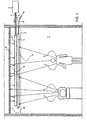
- a room 1 to be air-conditioned contains heat radiating objects such as people and devices through a perforated ceiling 2 with a cooling device heat change.
- the cooling device includes at least one Cooling element 3, which has a feed line 4 and a discharge line 5 directly or indirectly connected to a cooling unit 6 and is arranged vertically below the cooling element 3 Condensate pan 7 of somewhat larger area with one drain 8.
- the cooling device is above the perforated ceiling 2 arranged. However, it is also possible to use the condensate pan 7 to integrate into the ceiling 2, e.g. B. so that it is a Ceiling plate replaced.
- Above the cooling device preferably about 20-30 cm from the cooling element is one Ceiling or false ceiling 9 made of concrete or plaster.
- the cooling element 3 is among the Freezing point cooled, at least to -5 ° C, preferably but much deeper, e.g. B. to -40 ° C.
- the cooling element 3 is among the Freezing point cooled, at least to -5 ° C, preferably but much deeper, e.g. B. to -40 ° C.
- the cooling of the Room 1 is mainly done through radiation exchange the false ceiling 9 by immediate Radiation exchange with the icy cooling element strongly is cooled because the same is ideal in the infrared range black body comes very close and that of the False ceiling 9 outgoing radiation with high efficiency absorbed while it itself because of its low temperature radiates significantly less heat against the false ceiling 9.
- the false ceiling 9 exchanges on the other hand with the perforated Ceiling 2 heat radiation with room 1, especially with the Heat radiating objects in the same by being part of the heat radiation they emit absorbed and even because of their lower temperature radiates less heat than it absorbs. Part of the Radiation reaching false ceiling 9 becomes natural reflected and partially absorbed by the cooling element 3. Also the condensate pan 7 is exchanged with the radiation Cooling element 3 cooled and in turn carries through Exchange of radiation with room 1 to cool it. However, the temperature on the outside of the Condensate pan 7 does not drop below the dew point because otherwise condensate would form on its underside.
- the Heat exchange by radiation is straight in Fig. 1 Arrows indicated.
- the cooling effect of the radiation exchange which is known to follow a T 4 law, is very high.
- a strong cooling effect can also be achieved with a small cooling element 3.
- the air in room 1 always remains relatively dry, since excess air moisture is deposited on the cooling element 3 and iced up. In this way, optimal conditions are achieved without further measures for the room comfort.
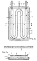
- the cooling element 3 is the cooling element 3 as an evaporator Steel sheet formed over a heat insulated Supply line 4 and a similar derivative 5 with the Cooling unit 6 (Fig. 1) is connected, in this case is designed as a capacitor.
- liquid coolant e.g. B. Freon
- the evaporator passed in a the lead 4 with the derivative 5th connecting meandering passage 10 evaporates and this cools the cooling element down to approx. -40 ° C.
- the steam is the cooling unit 6 through the derivative 5 fed and condensed there with heat extraction.
- the condensate tray arranged below the cooling element 3 7 has an outer shell 11 made of steel, which on the Outside is powder coated so that it is good there absorbed, and one inserted into the outer shell 11 Inner shell 12 made of polyurethane or rock wool or one other material with low thermal conductivity. At the Inside it is made of a reflective lining Provided metal foil. Due to the structure described in usually cooling the outside of the condensate pan 7 prevented below the dew point. If these measures not enough, the outer shell 11 can be easily heated become. In order to facilitate the drainage of condensate Condensate pan 7 slightly inclined towards the outlet 8.
- the Cooling device arranged at a distance below the same.
- the part of the above the cooling element 3 False ceiling 9 is by radiation exchange with the same strongly cooled and in turn cools room 1 Radiation exchange. Through heat conduction in the false ceiling 1 this effect is supported.
- the radiation exchange with the false ceiling 9 can - at least in the Initial phase of a cooling phase, if there is none Ice layer has formed - further reinforced by that the cooling element 3 at the top with a good absorbent paint is provided. Its the Condensate pan 7 facing the bottom is against it preferably formed reflective.
- the cooling element 3 is the cooling element 3 as a U-shaped steel tube 13 formed by which in the cooling unit 6 (Fig. 1) approx. -40 ° C cooled brine is passed.
- the cooling unit 6 Fig. 1
- the condensate pan 7 is basically constructed the same way according to the first embodiment, but it is on one pivotable axis 15 parallel to its longitudinal direction attached so that it can be removed from its position below the Cooling element 3 pivoted to the side by approx. 90 ° (arrow) can be.
- the cooling element 3 is then exposed and can be used Objects in room 1 enter into direct radiation exchange. In this way, a particularly strong cooling effect can be achieved as z. B. to cool down a overheated room at the beginning of a cooling phase can.
- the edges of the condensate pan 7 are slightly bent, so that any residue of condensate when swiveling the tub cannot leak.
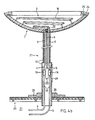
- the condensate pan 7 as a flat shell of z. B. the shape a spherical cap.
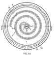
- the cooling element 3 is considered too a double spiral 16 bent part of a copper tube formed, which in the center of the condensate pan 7 in a thermally insulated supply line 4 and a similar discharge line 5 merges into a wide tube 17 made of sheet steel are drawn.
- the double spiral 16 can be provided with a vent valve.
- the tube 17 forms together with one surrounding it Base plate 26 a stand 27, the cooling element 3 and the condensate pan 7 carries.
- the foot plate 26 supports the Underside of a bottom element 28, which in different places of the floor 20 can be used by z. B. replaced a normal floor element.
- Somewhat above the Base plate 26 has tube 17 through a cover closable opening 29, behind which the Quick release couplings 18 and the collecting container 23 lie.
- Deflection elements for heat radiation to influence the spatial distribution of the cooling effect and possibly also Deflection elements for light may be attached.
- Another modification is the use of an evaporator or a Peltier element as a cooling element instead of the Double spiral 16.
- a Peltier element makes it superfluous especially when using a collecting container for the melted water, which is then only occasionally emptied must be -, the lead 4 and the lead 5 to Connection of the cooling element with the cooling unit in part to manufacture by tubes and rather allows them train completely or partially as a cable and with one Plug connection similar to an electrical plug connection with a suitable cooling installation, which z. B. may have a heat exchanger in each room that of the Peltier element or more generated heat dissipated by means of cooling medium and Cooling unit is transported. In this case, the Stand with a flat foot so that the Cooling device can be moved freely in the room like a standard lamp is.
- Peltier element as a cooling element especially with a removable workplace cooler is advantageous, it is of course also for fixed Cooling devices possible.
Landscapes
- Engineering & Computer Science (AREA)
- General Engineering & Computer Science (AREA)
- Chemical & Material Sciences (AREA)
- Sustainable Development (AREA)
- Combustion & Propulsion (AREA)
- Mechanical Engineering (AREA)
- Life Sciences & Earth Sciences (AREA)
- Devices For Blowing Cold Air, Devices For Blowing Warm Air, And Means For Preventing Water Condensation In Air Conditioning Units (AREA)
- Devices That Are Associated With Refrigeration Equipment (AREA)
- Drying Of Gases (AREA)
- Cold Air Circulating Systems And Constructional Details In Refrigerators (AREA)
- Details Of Measuring And Other Instruments (AREA)
- Blast Furnaces (AREA)
Description
- Fig. 1
- schematisch einen Schnitt durch einen Raum, der nach dem erfindungsgemässen Verfahren klimatisiert wird,
- Fig. 2a
- eine Draufsicht auf eine erste Ausführungsform einer erfindungsgemässen Vorrichtung zur Durchführung des erfindungsgemässen Verfahrens,
- Fig. 2b
- einen Querschnitt längs B-B durch die Vorrichtung von Fig. 2a,
- Fig. 3a
- eine Draufsicht auf eine zweite Ausführungsform einer erfindungsgemässen Vorrichtung zur Durchführung des erfindungsgemässen Verfahrens,
- Fig. 3b
- einen Querschnitt längs B-B durch die Vorrichtung von Fig. 3a,
- Fig. 4a
- eine Draufsicht auf eine dritte Ausführungsform einer erfindungsgemässen Vorrichtung zur Durchführung des erfindungsgemässen Verfahrens,
- Fig. 4b
- einen Querschnitt längs B-B durch die Vorrichtung von Fig. 4a,
Claims (12)
- Verfahren zur Klimatisierung eines Raumes (1) mittels mindestens eines innerhalb desselben angeordneten Kühlelements (3), das ausschliesslich durch Strahlung und allenfalls freie Konvektion mit dem zu kühlenden Raum Wärme austauscht, dadurch gekennzeichnet, dass Kühlphasen mit Regenerationsphasen abwechseln, wobei während einer Kühlphase jeweils die Temperatur des Kühlelements (3) derart eingestellt wird, dass sich an demselben bildendes Kondensat vereist und während einer Regenerationsphase jeweils derart, dass am Kühlelement (3) vereistes Kondensat abschmilzt.
- Verfahren nach Anspruch 1, dadurch gekennzeichnet, dass während einer Regenerationsphase jeweils allfällig abgeschmolzenes Kondensat aufgefangen und abgeleitet wird.
- Verfahren nach Anspruch 1 oder 2, dadurch gekennzeichnet, dass während einer Kühlphase jeweils die Temperatur des Kühlelements (3) auf eine Temperatur von höchstens -2°C eingestellt wird.
- Verfahren nach einem der Ansprüche 1 bis 3, dadurch gekennzeichnet, dass während einer Regenerationsphase jeweils das Kühlelement (3) abgeschaltet ist.
- Verfahren nach einem der Ansprüche 1 bis 4, dadurch gekennzeichnet, dass das Kühlelement (3) im Deckenbereich des zu kühlenden Raums (1) angeordnet ist.
- Verfahren nach Anspruch 5, dadurch gekennzeichnet, dass der Wärmeaustausch des Kühlelements (3) mit dem zu kühlenden Raum (1) überwiegend durch Strahlungsaustausch über oberhalb des Kühlelements (3) angeordnete Flächen erfolgt.
- Kühlvorrichtung zur Durchführung des Verfahrens nach einem der Ansprüche 1 bis 6, mit einem Kühlelement (3) sowie mit einem dasselbe tragenden Ständer (27), welcher auf einem Fussboden (20) abstützbar ist, dadurch gekennzeichnet, dass die Kühlvorrichtung eine ebenfalls von dem Ständer (27) getragene, senkrecht unterhalb des Kühlelements (3) angeordnete Kondensatwanne (7) aufweist, deren Aussenseite gegenüber ihrer dem Kühlelement (3) zugekehrten Innenseite thermisch isoliert ist und dass die Kühlvorrichtung Mittel zur Abwechslung von Kühlphasen und Regenerationsphasen aufweist sowie Mittel, die während der Kühlphase die Temperatur des Kühlelements (3) derart einstellen, dass sich an demselben bildendes Kondensat vereist und Mittel, die während der Regenerationsphase die Temperatur des Kühlelements (3) derart einstellen, dass am Kühlelement (3) vereistes Kondensat abschmilzt.
- Kühlvorrichtung nach Anspruch 7, dadurch gekennzeichnet, dass die Aussenseite der Kondensatwanne (7) absorbierend ausgebildet ist.
- Kühlvorrichtung nach Anspruch 7 oder 8, dadurch gekennzeichnet, dass die Innenseite der Kondensatwanne (7) reflektierend ausgebildet ist.
- Kühlvorrichtung nach einem der Anspruch 7 bis 9, dadurch gekennzeichnet, dass das Kühlelement (3) an der Oberseite absorbierend und an der der Kondensatwanne (7) zugewandten Unterseite reflektierend ausgebildet ist.
- Kühlvorrichtung nach einem der Ansprüche 7 bis 10, dadurch gekennzeichnet, dass das Kühlelement (3) über eine Zuleitung (4) und eine Ableitung (5), welche mindestens teilweise flexibel ausgebildet sind, mit einem Kühlaggregat (6) verbunden ist.
- Kühlvorrichtung nach einem der Ansprüche 7 bis 11, dadurch gekennzeichnet, dass das Kühlelement (3) als Rohr, als Verdampfer oder als Peltier-Element ausgebildet ist.
Applications Claiming Priority (4)
| Application Number | Priority Date | Filing Date | Title |
|---|---|---|---|
| CH3119/95 | 1995-11-03 | ||
| CH03119/95A CH691405A5 (de) | 1995-11-03 | 1995-11-03 | Verfahren und Vorrichtung zur Kühlung eines Raumes. |
| CH311995 | 1995-11-03 | ||
| PCT/CH1996/000387 WO1997017576A1 (de) | 1995-11-03 | 1996-11-01 | Verfahren und vorrichtung zur kühlung eines raumes |
Publications (2)
| Publication Number | Publication Date |
|---|---|
| EP0800638A1 EP0800638A1 (de) | 1997-10-15 |
| EP0800638B1 true EP0800638B1 (de) | 2003-02-12 |
Family
ID=4249022
Family Applications (1)
| Application Number | Title | Priority Date | Filing Date |
|---|---|---|---|
| EP96934299A Expired - Lifetime EP0800638B1 (de) | 1995-11-03 | 1996-11-01 | Verfahren und vorrichtung zur kühlung eines raumes |
Country Status (12)
| Country | Link |
|---|---|
| US (2) | US5996354A (de) |
| EP (1) | EP0800638B1 (de) |
| JP (1) | JP3212613B2 (de) |
| AT (1) | ATE232592T1 (de) |
| AU (1) | AU7275696A (de) |
| CA (1) | CA2209175C (de) |
| CH (1) | CH691405A5 (de) |
| DE (1) | DE59610131D1 (de) |
| DK (1) | DK0800638T3 (de) |
| ES (1) | ES2192232T3 (de) |
| PT (1) | PT800638E (de) |
| WO (1) | WO1997017576A1 (de) |
Families Citing this family (20)
| Publication number | Priority date | Publication date | Assignee | Title |
|---|---|---|---|---|
| WO1998049498A1 (de) * | 1997-04-30 | 1998-11-05 | Ernst Basler + Partner Ag | Verfahren und kühlelement zum kühlen eines büroinnenraumes |
| EP1009961B1 (de) * | 1997-05-16 | 2005-03-16 | Work Smart Energy Enterprises, Inc. | Hocheffiziente klimaanlage mit grosser luftmengenverteilung |
| US6405543B2 (en) * | 1997-05-16 | 2002-06-18 | Work Smart Energy Enterprises Inc. | High-efficiency air-conditioning system with high-volume air distribution |
| WO1999043990A1 (en) * | 1998-02-27 | 1999-09-02 | Watermaster Technologies Limited | Water making apparatus |
| AU2003259645B2 (en) * | 1998-02-27 | 2006-08-17 | Water Master Technologies Limited | Water making apparatus |
| US6466438B1 (en) * | 2000-04-17 | 2002-10-15 | Sui-Lin Lim | Generic external portable cooling device for computers |
| EP1225398A3 (de) * | 2001-01-18 | 2002-09-11 | Kunze, Christian, Ecole d'ingénieurs du canton de Vaud | Entfeuchter für die Platten einer Klimaanlage |
| US20070066213A1 (en) * | 2002-05-17 | 2007-03-22 | Andrew Helgeson | Variable air volume time modulated floor terminal |
| US6945866B2 (en) * | 2002-05-17 | 2005-09-20 | Airfixture L.L.C. | Method and apparatus for delivering conditioned air using pulse modulation |
| ATE319968T1 (de) * | 2002-11-22 | 2006-03-15 | Metallwaren Ag Heiterschen | Einrichtung zum heizen und kühlen eines raumes, deckenelement für eine solche einrichtung sowie verfahren zu ihrem betrieb |
| US7140426B2 (en) | 2003-08-29 | 2006-11-28 | Plascore, Inc. | Radiant panel |
| SI1541934T1 (sl) * | 2003-12-08 | 2006-12-31 | Barcol Air | Hladilni element, hladilna naprava in obratovalnipostopek |
| US20050183435A1 (en) * | 2004-02-23 | 2005-08-25 | Aubin Douglas E. | Home cooling cycle |
| WO2006070919A1 (en) | 2004-12-28 | 2006-07-06 | Canon Kabushiki Kaisha | Ink jet printing apparatus and ink processing method for same |
| JP5136708B1 (ja) * | 2012-02-29 | 2013-02-06 | 株式会社トヨックス | スタンド型輻射装置及び輻射空調システム |
| JP2015135197A (ja) * | 2014-01-16 | 2015-07-27 | 崇治 二枝 | 放射冷暖房装置 |
| DE102014009633A1 (de) * | 2014-06-27 | 2015-12-31 | Schmid Janutin Ag | Verfahren und Vorrichtung zur Belüftung und Temperierung von Räumen |
| US10883753B2 (en) | 2016-04-29 | 2021-01-05 | King Fahd University Of Petroleum And Minerals | Radiant cooling apparatus and system |
| JP2019143830A (ja) * | 2018-02-16 | 2019-08-29 | ダイキン工業株式会社 | 空気調和装置 |
| FR3113940B1 (fr) * | 2020-09-08 | 2022-08-12 | Scherrer Jean Marc | Dispositif rayonnant à condensation |
Family Cites Families (15)
| Publication number | Priority date | Publication date | Assignee | Title |
|---|---|---|---|---|
| US2498342A (en) * | 1950-02-21 | Pedestal type air conditioning unit | ||
| US1872728A (en) * | 1931-03-19 | 1932-08-23 | Bernard Gloekler Company | Refrigerating cabinet |
| US2140829A (en) * | 1936-06-01 | 1938-12-20 | Air Devices Corp | Air conditioning |
| US2251705A (en) * | 1939-05-24 | 1941-08-05 | Chrysler Corp | Artistic creation for interior decoration and human comfort |
| US2651503A (en) * | 1950-12-02 | 1953-09-08 | Reflectotherm Inc | System of radiant heat exchanging |
| US2708833A (en) * | 1953-02-27 | 1955-05-24 | Joseph G Nigro | Mobile air conditioning means for window openings |
| US2835186A (en) * | 1954-06-01 | 1958-05-20 | Whirlpool Co | Air conditioning system |
| US3611743A (en) * | 1969-11-19 | 1971-10-12 | Anthony J Manganaro | Room air conditioner |
| US3740964A (en) * | 1971-06-14 | 1973-06-26 | Tomeco Inc | Portable air conditioner |
| GB1596171A (en) * | 1977-01-19 | 1981-08-19 | Dantherm As | Air conditioning apparatuses |
| US4627245A (en) * | 1985-02-08 | 1986-12-09 | Honeywell Inc. | De-icing thermostat for air conditioners |
| JPS646631A (en) * | 1987-06-30 | 1989-01-11 | Komatsu Mfg Co Ltd | Radiation type space cooler/heater |
| US5216887A (en) * | 1987-06-30 | 1993-06-08 | Kabushiki Kaisha Komatsu Seisakusho | Radiative-type air-conditioning unit |
| US5363908A (en) * | 1990-02-24 | 1994-11-15 | Koester Helmut | Heating and cooling arrangement in particular of a structure suspended from a room ceiling |
| DE69214796T2 (de) * | 1991-08-20 | 1997-05-28 | Koester Helmut | Kühlanlage |
-
1995
- 1995-11-03 CH CH03119/95A patent/CH691405A5/de not_active IP Right Cessation
-
1996
- 1996-11-01 EP EP96934299A patent/EP0800638B1/de not_active Expired - Lifetime
- 1996-11-01 CA CA002209175A patent/CA2209175C/en not_active Expired - Fee Related
- 1996-11-01 JP JP51772097A patent/JP3212613B2/ja not_active Expired - Fee Related
- 1996-11-01 PT PT96934299T patent/PT800638E/pt unknown
- 1996-11-01 US US08/860,095 patent/US5996354A/en not_active Expired - Fee Related
- 1996-11-01 ES ES96934299T patent/ES2192232T3/es not_active Expired - Lifetime
- 1996-11-01 DK DK96934299T patent/DK0800638T3/da active
- 1996-11-01 AU AU72756/96A patent/AU7275696A/en not_active Abandoned
- 1996-11-01 DE DE59610131T patent/DE59610131D1/de not_active Expired - Fee Related
- 1996-11-01 AT AT96934299T patent/ATE232592T1/de not_active IP Right Cessation
- 1996-11-01 WO PCT/CH1996/000387 patent/WO1997017576A1/de not_active Ceased
-
1999
- 1999-08-06 US US09/369,269 patent/US6082126A/en not_active Expired - Fee Related
Also Published As
| Publication number | Publication date |
|---|---|
| US6082126A (en) | 2000-07-04 |
| DE59610131D1 (de) | 2003-03-20 |
| ATE232592T1 (de) | 2003-02-15 |
| MX9705011A (es) | 1997-10-31 |
| DK0800638T3 (da) | 2003-06-02 |
| WO1997017576A1 (de) | 1997-05-15 |
| AU7275696A (en) | 1997-05-29 |
| PT800638E (pt) | 2003-06-30 |
| US5996354A (en) | 1999-12-07 |
| JP3212613B2 (ja) | 2001-09-25 |
| JPH10506705A (ja) | 1998-06-30 |
| CA2209175A1 (en) | 1997-05-15 |
| ES2192232T3 (es) | 2003-10-01 |
| CH691405A5 (de) | 2001-07-13 |
| CA2209175C (en) | 2006-10-10 |
| EP0800638A1 (de) | 1997-10-15 |
Similar Documents
| Publication | Publication Date | Title |
|---|---|---|
| EP0800638A1 (de) | Verfahren und vorrichtung zur kühlung eines raumes | |
| DE60126834T2 (de) | Entfeuchtigungs- und klimaanlage | |
| DE102010021742A1 (de) | Vorrichtung zum Trocknen von Schüttgut in wenigstens einem Vorratsbehälter | |
| DE1476962A1 (de) | Kuehlschrank mit zwei thermisch isolierten Kammern und mit einem kompressorbetriebenen Kaelteapparat | |
| EP0041658B1 (de) | Anordnung zum Heizen oder Kühlen von klimatisierten Räumen in Wohnungen, Gewächshäusern oder dergleichen | |
| CH664004A5 (de) | Behaelter zum kuehlen eines kuehlgutes. | |
| EP3682778B1 (de) | Temperierkörper-anordnung sowie vorwand-anordnung mit einer solchen temperierkörper-anordnung | |
| DE3142621A1 (de) | Verfahren zum abfrosten an luftbehandlungsaggregaten mit waermepumpe und vorrichtung zur verfahrensausuebung | |
| EP1541934A1 (de) | Kühlelement sowie Kühleinrichtung und Verfahren zu ihrem Betrieb | |
| DE202009005518U1 (de) | Energiespeicher | |
| DE2930022A1 (de) | Solarenergie-sammel- und heizsystem | |
| DE19948782A1 (de) | Vorrichtung zur Kühlung des Innenraums eines Sarges | |
| DE102014222850A1 (de) | NoFrost-Kältegerät | |
| DE3007894A1 (de) | Tiefkuehltruhe | |
| DE3210271A1 (de) | Stall fuer die tierhaltung | |
| CH635632A5 (en) | Apparatus for the washing and optional drying of laundry | |
| DE10063227B4 (de) | Luftentfeuchter für pneumatische Bremskrafterzeuger | |
| EP1600711A2 (de) | Innenraum-Schneeanlage | |
| EP1570884B1 (de) | Skitunnel | |
| DE2650569A1 (de) | Trocknungsanlage mit getrennten, indirekt beheizten trockenkammern, insbesondere fuer ziegel | |
| DE2824618C2 (de) | Gerät zum Erwärmen und Kühlen fertiger Speisen | |
| DE10210991A1 (de) | Wintersporthalle und Verfahren zu deren Betreiben | |
| DE556737C (de) | Kuehlanlage, insbesondere fuer Verwendung von Trockeneis aus Kohlensaeure, mit seitlichem Luftabfallschacht | |
| DE1918801C (de) | Luftaufbereitungsanlage, vorzugsweise für Treibhäuser | |
| DE10160237A1 (de) | Schneesporthalle und Verfahren zu deren Betrieb |
Legal Events
| Date | Code | Title | Description |
|---|---|---|---|
| PUAI | Public reference made under article 153(3) epc to a published international application that has entered the european phase |
Free format text: ORIGINAL CODE: 0009012 |
|
| AK | Designated contracting states |
Kind code of ref document: A1 Designated state(s): AT BE CH DE DK ES FI FR GB GR IE IT LI LU MC NL PT SE |
|
| 17P | Request for examination filed |
Effective date: 19970705 |
|
| 17Q | First examination report despatched |
Effective date: 20000915 |
|
| GRAH | Despatch of communication of intention to grant a patent |
Free format text: ORIGINAL CODE: EPIDOS IGRA |
|
| GRAH | Despatch of communication of intention to grant a patent |
Free format text: ORIGINAL CODE: EPIDOS IGRA |
|
| GRAA | (expected) grant |
Free format text: ORIGINAL CODE: 0009210 |
|
| AK | Designated contracting states |
Designated state(s): AT BE CH DE DK ES FI FR GB GR IE IT LI LU MC NL PT SE |
|
| REG | Reference to a national code |
Ref country code: GB Ref legal event code: FG4D Free format text: NOT ENGLISH |
|
| REG | Reference to a national code |
Ref country code: CH Ref legal event code: EP |
|
| REF | Corresponds to: |
Ref document number: 59610131 Country of ref document: DE Date of ref document: 20030320 Kind code of ref document: P |
|
| REG | Reference to a national code |
Ref country code: CH Ref legal event code: NV Representative=s name: ZIMMERLI, WAGNER & PARTNER AG |
|
| REG | Reference to a national code |
Ref country code: GR Ref legal event code: EP Ref document number: 20030401567 Country of ref document: GR |
|
| REG | Reference to a national code |
Ref country code: DK Ref legal event code: T3 |
|
| REG | Reference to a national code |
Ref country code: SE Ref legal event code: TRGR |
|
| GBT | Gb: translation of ep patent filed (gb section 77(6)(a)/1977) | ||
| REG | Reference to a national code |
Ref country code: PT Ref legal event code: SC4A Free format text: AVAILABILITY OF NATIONAL TRANSLATION Effective date: 20030429 |
|
| REG | Reference to a national code |
Ref country code: IE Ref legal event code: FG4D Free format text: GERMAN |
|
| REG | Reference to a national code |
Ref country code: ES Ref legal event code: FG2A Ref document number: 2192232 Country of ref document: ES Kind code of ref document: T3 |
|
| ET | Fr: translation filed | ||
| PLBE | No opposition filed within time limit |
Free format text: ORIGINAL CODE: 0009261 |
|
| STAA | Information on the status of an ep patent application or granted ep patent |
Free format text: STATUS: NO OPPOSITION FILED WITHIN TIME LIMIT |
|
| 26N | No opposition filed |
Effective date: 20031113 |
|
| PGFP | Annual fee paid to national office [announced via postgrant information from national office to epo] |
Ref country code: GB Payment date: 20051026 Year of fee payment: 10 |
|
| PGFP | Annual fee paid to national office [announced via postgrant information from national office to epo] |
Ref country code: PT Payment date: 20051102 Year of fee payment: 10 |
|
| PGFP | Annual fee paid to national office [announced via postgrant information from national office to epo] |
Ref country code: DE Payment date: 20051103 Year of fee payment: 10 |
|
| PGFP | Annual fee paid to national office [announced via postgrant information from national office to epo] |
Ref country code: NL Payment date: 20051106 Year of fee payment: 10 |
|
| PGFP | Annual fee paid to national office [announced via postgrant information from national office to epo] |
Ref country code: SE Payment date: 20051107 Year of fee payment: 10 |
|
| PGFP | Annual fee paid to national office [announced via postgrant information from national office to epo] |
Ref country code: FR Payment date: 20051108 Year of fee payment: 10 |
|
| PGFP | Annual fee paid to national office [announced via postgrant information from national office to epo] |
Ref country code: MC Payment date: 20051110 Year of fee payment: 10 |
|
| PGFP | Annual fee paid to national office [announced via postgrant information from national office to epo] |
Ref country code: IE Payment date: 20051111 Year of fee payment: 10 Ref country code: GR Payment date: 20051111 Year of fee payment: 10 Ref country code: AT Payment date: 20051111 Year of fee payment: 10 |
|
| PGFP | Annual fee paid to national office [announced via postgrant information from national office to epo] |
Ref country code: FI Payment date: 20051114 Year of fee payment: 10 |
|
| PGFP | Annual fee paid to national office [announced via postgrant information from national office to epo] |
Ref country code: DK Payment date: 20051115 Year of fee payment: 10 |
|
| PGFP | Annual fee paid to national office [announced via postgrant information from national office to epo] |
Ref country code: CH Payment date: 20051121 Year of fee payment: 10 |
|
| PGFP | Annual fee paid to national office [announced via postgrant information from national office to epo] |
Ref country code: LU Payment date: 20051125 Year of fee payment: 10 |
|
| PGFP | Annual fee paid to national office [announced via postgrant information from national office to epo] |
Ref country code: ES Payment date: 20051219 Year of fee payment: 10 |
|
| PGFP | Annual fee paid to national office [announced via postgrant information from national office to epo] |
Ref country code: BE Payment date: 20060123 Year of fee payment: 10 |
|
| PG25 | Lapsed in a contracting state [announced via postgrant information from national office to epo] |
Ref country code: IE Free format text: LAPSE BECAUSE OF NON-PAYMENT OF DUE FEES Effective date: 20061101 Ref country code: FI Free format text: LAPSE BECAUSE OF NON-PAYMENT OF DUE FEES Effective date: 20061101 Ref country code: AT Free format text: LAPSE BECAUSE OF NON-PAYMENT OF DUE FEES Effective date: 20061101 |
|
| PG25 | Lapsed in a contracting state [announced via postgrant information from national office to epo] |
Ref country code: SE Free format text: LAPSE BECAUSE OF NON-PAYMENT OF DUE FEES Effective date: 20061102 |
|
| PG25 | Lapsed in a contracting state [announced via postgrant information from national office to epo] |
Ref country code: MC Free format text: LAPSE BECAUSE OF NON-PAYMENT OF DUE FEES Effective date: 20061130 Ref country code: LI Free format text: LAPSE BECAUSE OF NON-PAYMENT OF DUE FEES Effective date: 20061130 Ref country code: DK Free format text: LAPSE BECAUSE OF NON-PAYMENT OF DUE FEES Effective date: 20061130 Ref country code: CH Free format text: LAPSE BECAUSE OF NON-PAYMENT OF DUE FEES Effective date: 20061130 Ref country code: BE Free format text: LAPSE BECAUSE OF NON-PAYMENT OF DUE FEES Effective date: 20061130 |
|
| PGFP | Annual fee paid to national office [announced via postgrant information from national office to epo] |
Ref country code: IT Payment date: 20061130 Year of fee payment: 11 |
|
| PG25 | Lapsed in a contracting state [announced via postgrant information from national office to epo] |
Ref country code: PT Free format text: LAPSE BECAUSE OF NON-PAYMENT OF DUE FEES Effective date: 20070502 |
|
| REG | Reference to a national code |
Ref country code: PT Ref legal event code: MM4A Free format text: LAPSE DUE TO NON-PAYMENT OF FEES Effective date: 20070502 |
|
| PG25 | Lapsed in a contracting state [announced via postgrant information from national office to epo] |
Ref country code: NL Free format text: LAPSE BECAUSE OF NON-PAYMENT OF DUE FEES Effective date: 20070601 Ref country code: DE Free format text: LAPSE BECAUSE OF NON-PAYMENT OF DUE FEES Effective date: 20070601 |
|
| REG | Reference to a national code |
Ref country code: DK Ref legal event code: EBP |
|
| REG | Reference to a national code |
Ref country code: CH Ref legal event code: PL |
|
| EUG | Se: european patent has lapsed | ||
| GBPC | Gb: european patent ceased through non-payment of renewal fee |
Effective date: 20061101 |
|
| NLV4 | Nl: lapsed or anulled due to non-payment of the annual fee |
Effective date: 20070601 |
|
| REG | Reference to a national code |
Ref country code: FR Ref legal event code: ST Effective date: 20070731 |
|
| REG | Reference to a national code |
Ref country code: IE Ref legal event code: MM4A |
|
| PG25 | Lapsed in a contracting state [announced via postgrant information from national office to epo] |
Ref country code: GB Free format text: LAPSE BECAUSE OF NON-PAYMENT OF DUE FEES Effective date: 20061101 |
|
| BERE | Be: lapsed |
Owner name: *BARCOL-AIR A.G. Effective date: 20061130 |
|
| REG | Reference to a national code |
Ref country code: ES Ref legal event code: FD2A Effective date: 20061102 |
|
| PG25 | Lapsed in a contracting state [announced via postgrant information from national office to epo] |
Ref country code: FR Free format text: LAPSE BECAUSE OF NON-PAYMENT OF DUE FEES Effective date: 20061130 Ref country code: ES Free format text: LAPSE BECAUSE OF NON-PAYMENT OF DUE FEES Effective date: 20061102 |
|
| PG25 | Lapsed in a contracting state [announced via postgrant information from national office to epo] |
Ref country code: LU Free format text: LAPSE BECAUSE OF NON-PAYMENT OF DUE FEES Effective date: 20061101 |
|
| PG25 | Lapsed in a contracting state [announced via postgrant information from national office to epo] |
Ref country code: GR Free format text: LAPSE BECAUSE OF NON-PAYMENT OF DUE FEES Effective date: 20070604 |
|
| PG25 | Lapsed in a contracting state [announced via postgrant information from national office to epo] |
Ref country code: IT Free format text: LAPSE BECAUSE OF NON-PAYMENT OF DUE FEES Effective date: 20071101 |