EP0800655B1 - Methode et dispositif pour determiner au moins un parametre caracteristique d'un corps - Google Patents
Methode et dispositif pour determiner au moins un parametre caracteristique d'un corps Download PDFInfo
- Publication number
- EP0800655B1 EP0800655B1 EP96934970A EP96934970A EP0800655B1 EP 0800655 B1 EP0800655 B1 EP 0800655B1 EP 96934970 A EP96934970 A EP 96934970A EP 96934970 A EP96934970 A EP 96934970A EP 0800655 B1 EP0800655 B1 EP 0800655B1
- Authority
- EP
- European Patent Office
- Prior art keywords
- radiation
- intensity
- phase
- polychromatic
- passed
- Prior art date
- Legal status (The legal status is an assumption and is not a legal conclusion. Google has not performed a legal analysis and makes no representation as to the accuracy of the status listed.)
- Expired - Lifetime
Links
- 238000000034 method Methods 0.000 title claims description 54
- 230000005855 radiation Effects 0.000 claims description 62
- 238000001228 spectrum Methods 0.000 claims description 34
- 239000000203 mixture Substances 0.000 claims description 17
- 238000003325 tomography Methods 0.000 claims description 10
- 238000009826 distribution Methods 0.000 claims description 9
- 239000011435 rock Substances 0.000 claims description 9
- 238000005259 measurement Methods 0.000 claims description 8
- 238000004458 analytical method Methods 0.000 claims description 7
- 239000000470 constituent Substances 0.000 claims description 7
- 239000003208 petroleum Substances 0.000 claims description 4
- 239000002131 composite material Substances 0.000 claims description 3
- 238000011156 evaluation Methods 0.000 claims description 3
- 238000012545 processing Methods 0.000 claims description 2
- 239000000523 sample Substances 0.000 description 42
- 230000006870 function Effects 0.000 description 16
- 238000002834 transmittance Methods 0.000 description 13
- 239000002250 absorbent Substances 0.000 description 11
- 230000002745 absorbent Effects 0.000 description 11
- 238000004088 simulation Methods 0.000 description 8
- 208000031968 Cadaver Diseases 0.000 description 6
- 229910052729 chemical element Inorganic materials 0.000 description 5
- 238000006073 displacement reaction Methods 0.000 description 5
- 239000000126 substance Substances 0.000 description 5
- 229920000297 Rayon Polymers 0.000 description 4
- 238000010521 absorption reaction Methods 0.000 description 4
- 238000010894 electron beam technology Methods 0.000 description 4
- BASFCYQUMIYNBI-UHFFFAOYSA-N platinum Chemical compound [Pt] BASFCYQUMIYNBI-UHFFFAOYSA-N 0.000 description 4
- 239000002964 rayon Substances 0.000 description 4
- 239000000463 material Substances 0.000 description 3
- 239000011159 matrix material Substances 0.000 description 3
- OKTJSMMVPCPJKN-UHFFFAOYSA-N Carbon Chemical compound [C] OKTJSMMVPCPJKN-UHFFFAOYSA-N 0.000 description 2
- RYGMFSIKBFXOCR-UHFFFAOYSA-N Copper Chemical compound [Cu] RYGMFSIKBFXOCR-UHFFFAOYSA-N 0.000 description 2
- PNEYBMLMFCGWSK-UHFFFAOYSA-N aluminium oxide Inorganic materials [O-2].[O-2].[O-2].[Al+3].[Al+3] PNEYBMLMFCGWSK-UHFFFAOYSA-N 0.000 description 2
- 239000003054 catalyst Substances 0.000 description 2
- 239000013256 coordination polymer Substances 0.000 description 2
- 238000012937 correction Methods 0.000 description 2
- 238000001514 detection method Methods 0.000 description 2
- 239000012530 fluid Substances 0.000 description 2
- 239000010439 graphite Substances 0.000 description 2
- 229910002804 graphite Inorganic materials 0.000 description 2
- 230000003993 interaction Effects 0.000 description 2
- 229910052697 platinum Inorganic materials 0.000 description 2
- 239000011148 porous material Substances 0.000 description 2
- 238000013519 translation Methods 0.000 description 2
- 238000002083 X-ray spectrum Methods 0.000 description 1
- 230000001133 acceleration Effects 0.000 description 1
- 230000006399 behavior Effects 0.000 description 1
- 210000004027 cell Anatomy 0.000 description 1
- 238000012512 characterization method Methods 0.000 description 1
- 238000006243 chemical reaction Methods 0.000 description 1
- 239000013626 chemical specie Substances 0.000 description 1
- 150000001875 compounds Chemical class 0.000 description 1
- 238000007796 conventional method Methods 0.000 description 1
- 229910052802 copper Inorganic materials 0.000 description 1
- 239000010949 copper Substances 0.000 description 1
- 239000011889 copper foil Substances 0.000 description 1
- 238000005336 cracking Methods 0.000 description 1
- 230000001186 cumulative effect Effects 0.000 description 1
- 238000010586 diagram Methods 0.000 description 1
- 239000010433 feldspar Substances 0.000 description 1
- PCHJSUWPFVWCPO-UHFFFAOYSA-N gold Chemical compound [Au] PCHJSUWPFVWCPO-UHFFFAOYSA-N 0.000 description 1
- 239000010931 gold Substances 0.000 description 1
- 229910052737 gold Inorganic materials 0.000 description 1
- 229910052500 inorganic mineral Inorganic materials 0.000 description 1
- 230000010354 integration Effects 0.000 description 1
- 238000004519 manufacturing process Methods 0.000 description 1
- 230000015654 memory Effects 0.000 description 1
- 229910052751 metal Inorganic materials 0.000 description 1
- 239000002184 metal Substances 0.000 description 1
- 238000010603 microCT Methods 0.000 description 1
- 239000011707 mineral Substances 0.000 description 1
- 230000003071 parasitic effect Effects 0.000 description 1
- 229920003229 poly(methyl methacrylate) Polymers 0.000 description 1
- 239000004926 polymethyl methacrylate Substances 0.000 description 1
- 238000011002 quantification Methods 0.000 description 1
- 239000010453 quartz Substances 0.000 description 1
- VYPSYNLAJGMNEJ-UHFFFAOYSA-N silicon dioxide Inorganic materials O=[Si]=O VYPSYNLAJGMNEJ-UHFFFAOYSA-N 0.000 description 1
- 239000007787 solid Substances 0.000 description 1
Images
Classifications
-
- G—PHYSICS
- G01—MEASURING; TESTING
- G01T—MEASUREMENT OF NUCLEAR OR X-RADIATION
- G01T1/00—Measuring X-radiation, gamma radiation, corpuscular radiation, or cosmic radiation
- G01T1/16—Measuring radiation intensity
-
- G—PHYSICS
- G01—MEASURING; TESTING
- G01T—MEASUREMENT OF NUCLEAR OR X-RADIATION
- G01T1/00—Measuring X-radiation, gamma radiation, corpuscular radiation, or cosmic radiation
- G01T1/16—Measuring radiation intensity
- G01T1/169—Exploration, location of contaminated surface areas
-
- G—PHYSICS
- G01—MEASURING; TESTING
- G01T—MEASUREMENT OF NUCLEAR OR X-RADIATION
- G01T1/00—Measuring X-radiation, gamma radiation, corpuscular radiation, or cosmic radiation
- G01T1/36—Measuring spectral distribution of X-rays or of nuclear radiation spectrometry
Definitions
- the present invention relates to a method for determine at least one characteristic parameter of a body to be analyzed, said body being crossed over a certain thickness by a polychromatic radiation having a known frequency spectrum and an intensity I, said body consisting of one or more phases of composition known, for the purpose, for example, of correcting reconstruction artifacts or quantification.
- the method according to the invention makes it possible to take account for example of different factors: the chemical composition of the body, the energy distribution of the beam polychromatic, the constituent elements of said body, or the variation of the coefficient radiation absorption etc.
- the method according to the invention is particularly suitable for modeling and / or correcting the hardening of a beam from polychromatic radiation passing through a absorbent body.
- the expression “hardening of a beam” is used to designate, the increase in the average energy of a beam during the crossing of a body absorbent.
- the present invention applies particularly well to simulate hardening of an X-ray beam and correct the artifacts introduced by this hardening.
- the method according to the invention finds applications in particular for measuring the "effective" thickness of material, crossed by a polychromatic beam of X-rays in an absorbent body of known chemical composition.
- the method according to the invention finds applications in particular in the context of the characterization of rocks (reservoir rocks) in the petroleum field.
- One of the methods is to use a filter, for example a plate of material absorbing at least part of the radiation and more particularly the weakest energies.
- a filter for example a plate of material absorbing at least part of the radiation and more particularly the weakest energies.
- this method has the disadvantage of absorbing part of the beam and lead to a loss of intensity.
- a calibration is carried out using a model sample or reference.
- a sample must be homogeneous in composition and present an attenuation close to that of the object to be analyzed and it is not always possible to meet these last two selection criteria.
- Patent EP 0 045 156 teaches a method for determining the characteristics of an X-ray, for example the energy of RX and the source.
- US Patent 5,095,431 describes a method for calibrating an X-ray in using standard shapes different from a circular shape.
- US Patent 5,440,386 mentions the use of shims of various thicknesses for quickly calibrate detectors used in a thickness profile measuring device by X-rays.
- the object of the method according to the invention is to change the intensity variation of a polychromatic radiation with a known frequency spectrum, after crossing of a certain thickness of a body or object, consisting of one or more phases of known composition, in order to correct nature-related errors or artifacts polychromatic radiation.
- the variation in intensity is evaluated selectively for one or more frequency bands of the radiation.
- polychromatic radiation is used, emitted according to several directions and we determine the distribution of one or more constituents of the body in at minus an area traversed by said radiation.
- the present invention relates to a device making it possible, for example, to tomography of a body made up of several phases of composition known by evaluation of the variation in intensity of a polychromatic radiation having a spectrum of known frequencies, after crossing a certain thickness of said body.
- the polychromatic radiation source is for example integral with the guide and / or of support.
- the method can be used for example to simulate the hardening of a polychromatic radiation having passed through a body, or even to characterize a sample, such as a rock sample or a composite, in the petroleum field.
- the method according to the invention finds applications throughout the area of analyzes based on the exploitation of X-rays. It allows in particular to increase the phase discrimination power currently obtained by classic techniques.
- the method according to the invention is advantageously used to control the texture of catalysts, of composite materials for example, more generally, to study body by tomography.
- the energy spectrum of a beam from polychromatic radiation passing through an absorbent body is modified due in particular to its interaction with the chemical elements making up the body. This change also depends on the values beam energy because the absorption coefficient or attenuation coefficient of the body varies with energy.
- the body is composed of several chemical species and also of several phases having different natures.
- I I 0 exp (- ⁇ t) where I is the intensity of the monochromatic beam having passed through the body, I 0 the intensity of the beam before crossing the body, t is the thickness of the body, and ⁇ is the absorption coefficient linked to the energy of the monochromatic beam , determined by taking into account the absorption cross-sections and the atomic densities of the elements.
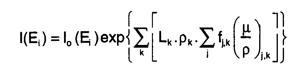
- the intensity value I of the beam having passed through at least one phase k over a length L k is determined for an energy value Ei given using the following relation:
- TRP polychromatic transmittance values
- TRM monochromatic beams
- the subdivision step is chosen in particular with respect to the precision that is wishes to obtain and / or according to the characteristic dimensions of the phases.
- the initial intensity of the beam taken into account in the expression can be an intensity obtained for the preceding layer from the simulation function 1.
- an absorbent body 3 has been shown diagrammatically by a stack of layers having thicknesses C i , for example each corresponding to a phase of a different nature.
- the method according to the invention makes it possible for example to simulate the hardening of the beam of polychromatic radiation.
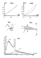
- Figures 1A and 1B graphically show two examples of conversion tables thus obtained respectively for monochromatic beams of energy of 14 keV and 10 keV for a quartz sample and an X source on a gold target.
- Source X spectrum data before and after crossing the sample, as well as the simulation function, are for example stored in a microcontroller 11 (Fig. 8).
- the X-ray source polychromatic which is for example a synchrotron type radiation, or even a source produced by bombardment of an electron beam 1 on a target 2, generating X-rays towards the sample or absorbent material 3.
- the radiation from the sample is received by a detector 4 such as a spectrometer positioned so as to collect the spectrum of X-rays having passed through the absorbent body.
- the body 3 located between the source and the detector 4 has an input surface Se located on the side of the X-ray and an exit surface Ss located on the side of detector 4 (Fig. 3).
- the X-ray beam is sent at an angle of incidence ⁇ relative to a plane of the body, that of its entrance face for example.
- X-rays pass through the body in a direction perpendicular to its entry surface Se and spring modified by the exit surface Ss of the body before being detected by the spectrometer 4.
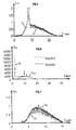
- Figures 4 and 5 show the simulation results obtained when the body absorbent is a sample of polymethyl methacrylate (PPMA) of about 1 mm thick.
- PPMA polymethyl methacrylate
- FIG. 4 shows the spectra given by the curves I 1 and I 2 and measured respectively from the X-ray source before and after the passage of a PPMA sample having a thickness of 1 mm.
- the electron acceleration voltage in this example is 25 kV and the target chosen is a copper foil 1 ⁇ m thick. Copper provides a main line at 8 keV, an energy which has an attenuation of around 47%. Curve I 2 of FIG. 4 nevertheless shows that the attenuation of energies below 5 keV is almost total, and that the attenuation of the spectrum is approximately 36%.
- the spectra of the polychromatic radiation of rays after the crossing of a sample respectively, measured referenced I 2 in FIG. 4, and simulated referenced I 3 in FIG. 5, are substantially identical, and so are the intensity values of the beam determined using the modeling function (1) are substantially identical to the beam intensity values measured by the spectrometer 4 after crossing the sample, which validates this simulation method.
- a filter to attenuate the low energies of the spectrum, or high-pass filter, these the latter being responsible for the most important artifacts, therefore for the hardest important.
- Figures 6 and 7 validate the simulation method applying the function (1).
- the curves I x and I xz respectively show the intensity spectrum of the beam obtained for a source X and the intensity spectrum of the beam filtered using a graphic filter.
- the modeling function (1) is applied to each of the energy values of the curve I xz in FIG. 6 by assimilating the body modeled in the function by the assembly made up of the absorbent body and the filter, and the values are determined. corrected intensity which are represented on the curve I M.
- one of the implementations of the method makes it possible to determine the thickness of a sample whose chemical and mineralogical composition is known.
- effective thickness is meant the actual thickness of solids passed through while account for the angle of incidence of the X-ray. Knowing the angle of incidence of the beam, it is possible to go back to the value of the thickness crossed.
- the implementation of the method according to the invention also makes it possible to determine the concentration of an element and / or a phase contained in a body of which we know the chemical and / or mineralogical nature.
- the concentration of platinum in a catalyst having as matrix alumina is known, and we calculate the values of the transmitted intensity corresponding to values of concentration of platinum and / or alumina. These determined intensity values are then stored for example in a table in the form of a couple (intensity of X-ray beam, composition of a selected phase).
- a measurement is then made of the intensity of the X-rays having passed through the body to be analyzed, namely the matrix and the element, and we compare this measured value to values determined and stored in the data table.
- the method for determining the variation in intensity of an X-ray beam having passed through a sample can advantageously be used in applications for tomography, and in particular for carrying out microtomographies of a sample.
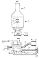
- Figure 8 shows schematically a microtomograph which presents in particular as advantage of obtaining precision in the resolution in the micrometer range.
- the resolution obtained for the measurements varies between 0.5 and 10 ⁇ m, and preferably between 1 and 5 ⁇ m.
- the microtomograph shown diagrammatically in FIG. 8 consists of two parts, a column 5 and a drawer 6, for example.
- the column is for example a column of a conventional electron microscope and will therefore not be described in detail.
- the drawer 6 comprises the targets 2 bombarded by the electron beam, which are the source of the X-ray radiation, having characteristics substantially identical to those given in FIG. 4 (spectrum I 1 ).
- the axis of rotation 8 allows the sample to tilt according to a arrow shown diagrammatically in the figure, its lateral displacement is achieved, for example, by a translation of the assembly, axis of rotation, sample holder.
- Figure 9 shows in detail an alternative embodiment of the device of Figure 8 allowing in particular to improve the tomographic resolution.
- the reconstructed section means the reconstructed section of the sample or body, perpendicular to the axis of rotation, and which is defined by the position of the source of polychromatic radiation and the position of the detector.
- the value of the ratio L / d is preferably greater than or equal to 1.
- the arrangement of the elements described above advantageously makes it possible to carry out the displacement of the sample inside the column, for example so as to obtain several reconstructed sections of the sample. From these reconstructed sections, it is possible to perform tomography of the sample.
- the displacement device 17 is connected to a control means displacements to obtain the displacement value precisely and so that optimize the cross-checking of the different reconstructed sections.
- the target 2 is made integral with the guide, directly or indirectly using conventional connecting means, shown schematically by dotted lines on the face.
- the figure shows schematically its direct connection with the support.
- Such an embodiment makes it possible in particular to increase the resolution and to achieve resolutions s between 0.5 and 10 ⁇ m and preferably between 1 and 5 ⁇ m.
- the guide is directly secured to the column by conventional fixing means.
- the sample can be rotated manually in multiples of 3 ° or plus, for example which corresponds to a maximum of 120 rotations per complete revolution.
- a another way to do this is to automate the rotation using a device suitable, this variant making it possible to increase the number of steps and to go to 1200 steps per complete turn.
- the detection device 10 of the beam having passed through the sample comprises, by example a CCD camera which can be associated with any device allowing to overcome parasitic effects and to increase the quality and accuracy of the measurements.
- the device detection 10 is associated with a processing system 11 programmed to implement conventional methods of tomography and moreover the method of evaluation of variation intensity according to the invention
- the energy of the electron beam is chosen, for example so as to maximize the production of the photons of the chosen line, the upper limit being given by the capacity of the high voltage tank of the electronic column in this exemplary embodiment.
- the beam current is adjusted to obtain an intense beam while keeping a probe small electronics.
- the choice of the sample rotation pitch is fixed to obtain a spatial resolution of the order of that of the projections, the number of projections M obeying to the following law M is greater than or equal to ⁇ / 2 * N where N is the number of pixels in a line projections.
- the method then consists in acquiring a set of intensity values associated with angles of rotation of the sample, for an X-ray beam. data table with measured intensity values Mi and angle values ⁇ i.
- the intensity values I Mi obtained for several monochromatic beams have been determined, in a range of energy values comprising at least the energy values of the spectrum of the radiation sent to the sample and at different sample thicknesses. , so as to constitute the reference model.
- These two sets of values are combined, for example into a single data table and stored in the microcontroller.
- each of the measured intensity values Mi is compared to the intensity values determined for the polychromatic beam I Pi , and after comparison, the measured value Mi is replaced by the closest determined value.
- the value I Pi is then compared with the values obtained for monochromatic beams and the intensity value which one would have obtained using a monochromatic beam, the closest for example, is kept. This value will be used in the tomography software to determine and characterize the sample area crossed.
Landscapes
- Physics & Mathematics (AREA)
- Spectroscopy & Molecular Physics (AREA)
- Health & Medical Sciences (AREA)
- Life Sciences & Earth Sciences (AREA)
- General Physics & Mathematics (AREA)
- High Energy & Nuclear Physics (AREA)
- Molecular Biology (AREA)
- Analysing Materials By The Use Of Radiation (AREA)
- Measurement Of Radiation (AREA)
Description

- On compare la variation d'intensité mesurée après traversée de ladite épaisseur du corps à analyser avec les valeurs de variations déduites du modèle, et
- On détermine le ou lesdits paramètres caractéristiques du corps analysé.
- pour évaluer la variation d'intensité en appliquant le modèle défini par la relation (1)
suivante :

- I → intensité du rayonnement X
- Ei → énergie du canal i du spectre X
- Lk → longueur traversée dans la phase k
- ρk → densité de la phase k
- fj,k → fraction de l'élément j dans la phase
- pour comparer la variation d'intensité mesurée après traversée de ladite épaisseur du corps à analyser avec les valeurs de variations déduites du modèle, et
- pour déterminer au moins un paramètre caractéristique du corps analysé.
- en minéralogie pour identifier des minéraux au sein d'une roche et étudier leur distribution éventuelle,
- en mécanique des fluides en milieux poreux, par exemple pour définir la géométrie de grains ou de pores et leur connexité, ces paramètres ayant une influence non négligeable sur le comportement du fluide circulant à l'intérieur,
- en mécanique des roches, par exemple pour vérifier l'état de micro-fissuration des échantillons de roche,
- pour contrôler par tomographie des roches réservoirs.
- les figures 1A et 1B représentent des tables de correspondance entre des valeurs de transmittance observées pour un faisceau polychromatique (TRP) et des valeurs de transmittance pour un faisceau monochromatique (TRM) pour deux valeurs d'intensité;
- les figures 2, 3 montrent schématiquement un exemple de réalisation pour un montage permettant de valider la méthode selon l'invention,
- la figure 4 montre schématiquement les spectres Sf respectifs du rayonnement avant traversée d'un échantillon (II) et après sa traversée (I2);
- la figure 5 montre schématiquement les spectres Sf respectifs du rayonnement polychromatique de rayons X, après traversée de l'échantillon, le premier (I2) étant celui mesuré et le deuxième (I3) étant déduit du modèle;
- la figure 6 montre schématiquement les spectres Sf respectifs du rayonnement polychromatique de rayons X, le premier (Ix) étant celui de la source, le deuxième (Ixf) étant celui filtré à travers une plaque de graphite;
- la figure 7 montre schématiquement les spectres Sf respectifs du rayonnement polychromatique de rayons X, le premier (Ie) étant celui obtenu expérimentalement après passage à travers un filtre et l'échantillon analysé, le deuxième (IM) étant le spectre correspondant obtenu par le modèle; et
- la figure 8 représente schématiquement un exemple d'application de la méthode pour réaliser la tomographie d'un échantillon, et
- la figure 9 schématise une variante de réalisation d'un dispositif selon l'invention permettant d'obtenir une meilleure résolution.
- on mémorise les paramètres indicatifs de cette composition dans des mémoires, celles par exemple d'un micro-contrôleur, sous forme de tables de données,
- connaissant les éléments chimiques constitutifs des phases, la densité de ces phases et le coefficient massique d'atténuation pour chaque élément chimique j d'une phase k, on a accès au coefficient d'atténuation massique du faisceau dans chacune de ces phases,
- à partir d'une hypothèse faite sur la répartition des phases k ou d'une connaissance préalable de leur répartition, il est possible d'évaluer la distance ou l'épaisseur Lk effectivement traversée par le faisceau, c'est-à-dire la distance qui tient compte de l'angle d'incidence du faisceau par rapport à un axe du corps,
- par ailleurs, on a mémorisé le spectre d'énergie du faisceau indicent, avant traversée du corps, par exemple sous forme d'un tableau de valeurs intensité/énergie.
- on établit le modèle de référence en déterminant des séries de valeurs d'intensité du rayonnement monochromatique à l'aide de la fonction de modélisation (1) pour différentes valeurs d'énergie, et pour différentes couches Ci, et l'on mémorise ces données, par exemple dans le micro-contrôleur,
- on effectue ensuite une série de mesures d'intensité du faisceau polychromatique de rayons X après traversée de l'échantillon, et on mémorise ces données dans le micro-contrôleur, ceci pour plusieurs zones de l'échantillon,
- on compare ensuite chacune des valeurs d'intensité mesurées aux valeurs déterminées pour le modèle et on lui associe, par exemple la valeur d'intensité la plus proche fournie par lui, et
- sachant qu'à une valeur d'intensité est associée une épaisseur ou couche CP, on en déduit la valeur de l'épaisseur effective de la zone traversée par le faisceau.
- un guide 12, ayant deux extrémités 12a et 12b et une longueur L, est disposé autour de l'axe de rotation 8 de manière classique pour que l'axe de rotation conserve ses déplacements en rotation et en translation éventuellement,
- le guide est solidaire d'une semelle 13 qui coulisse sur un support 14 à l'aide de vis de guidage 15,
- le support 14 est rendu solidaire de la paroi de la colonne, par exemple au niveau du tiroir 6 par des moyens de fixation 16 habituellement utilisés,
- la semelle 13 est reliée à un dispositif 17 passant à travers la paroi de la colonne et qui permet de commander son déplacement de façon manuelle ou automatiquement,
- l'axe de rotation 8 est relié à un moteur 18 par l'intermédiaire d'un ensemble 19 de joints homocinétiques connus de l'homme du métier. Ces joints assurent l'indépendance entre le moteur et le guide et/ou les déplacements de ce guide,
- le porte échantillon 7 est fixé à une extrémité de l'axe de rotation 8, et supporte l'échantillon 9 à analyser,
- on définit "d" comme étant la distance séparant l'extrémité du guide 12b la plus éloignée de la paroi de la colonne de la section reconstruite de l'échantillon.
Claims (13)
- Méthode pour déterminer au moins un paramètre caractéristique d'un corps à analyser, ledit corps étant traversé sur une certaine épaisseur par un rayonnement polychromatique ayant un spectre de fréquence connu et une intensité I, ledit corps étant constitué d'une ou de plusieurs phases de composition connue, dans le but de corriger des erreurs liées aux artefacts liés à la nature polychromatique du rayonnement, caractérisée en ce que :on évalue la variation d'intensité du rayonnement en appliquant le modèle défini par la relation (1) suivante :
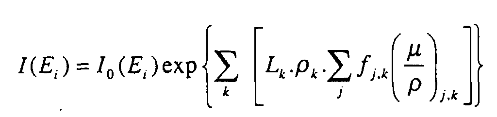 I → intensité du rayonnement XEi → énergie du canal i du spectre XLk → longueur traversée dans la phase kρk → densité de la phase kfj,k → fraction de l'élément j dans la phase→ coefficient d'atténuation massique pour chaque élément j de la phase k.
 on compare la variation d'intensité mesurée après traversée de ladite épaisseur du corps à analyser avec les valeurs de variations déduites du modèle, eton détermine le ou lesdits paramètres caractéristiques du corps analysé.
 - Méthode selon la revendication 1 caractérisée en ce que l'on modélise les influences respectives de paramètres caractéristiques d'une pluralité de couches successivement traversées par le rayonnement.
- Méthode selon l'une des revendications 1 à 2 caractérisée en ce que l'on évalue la variation d'intensité sélectivement pour une ou plusieurs bandes de fréquence du rayonnement.
- Méthode selon l'une des revendications 1 à 3 caractérisée en ce que la composition du corps analysé étant connue, on détermine par comparaison l'épaisseur effective de la zone traversée par le rayonnement.
- Méthode selon l'une des revendications 1 à 3 caractérisée en ce que l'épaisseur du corps analysé étant connue, on détermine par comparaison la concentration de la zone traversée par le rayonnement en un ou plusieurs de ses constituants.
- Méthode selon l'une des revendications caractérisée en ce que l'on effectue plusieurs mesures d'intensité du rayonnement ayant traversé au moins ladite zone du corps analysé en faisant varier l'angle d'incidence du rayonnement par rapport à cette zone, on associe à chacune desdites valeurs mesurées une valeur d'intensité déterminée à partir d'un rayonnement polychromatique puis une valeur d'intensité déterminée pour un rayonnement monochromatique, et à partir desdites valeurs on déduit la composition de ladite zone traversée par le rayonnement.
- Méthode selon la revendication 6, caractérisée en ce que l'on irradie un corps étudié au moyen d'un faisceau de rayonnement X polychromatique, suivant plusieurs directions et on détermine la distribution de constituants du corps dans au moins une zone traversée par ledit rayonnement.
- Dispositif pour déterminer au moins une caractéristique d'un corps constitué d'une ou plusieurs phases de composition connues par évaluation de la variation d'intensité d'un rayonnement polychromatique ayant un spectre de fréquences connu, après traversée d'une certaine épaisseur dudit corps, comportant au moins une enceinte (6), ladite enceinte pouvant contenir ledit corps, une source d'un rayonnement polychromatique, au moins un dispositif (10) pour détecter le rayonnement après traversée dudit corps, un ensemble pour maintenir ledit corps (9) à l'intérieur de ladite enceinte, un axe de rotation (8), ledit ensemble comportant au moins un guide (12) de longueur « L » et entourant sur au moins une partie de sa longueur ledit axe de rotation (8) caractérisé en ce qu'il comporte au moins un systsème de traitement (11) adapté :pour évaluer cette variation d'intensité en appliquant le modèle défini par la relation (1) suivante :
 I → intensité du rayonnement XEi → énergie du canal i du spectre XLk → longueur traversée dans la phase kρ k → densité de la phase kfj,k → fraction de l'élément j dans la phase→ coefficient d'atténuation massique pour chaque élément j de la phase k
 pour comparer la variation d'intensité mesurée après traversée de ladite épaisseur du corps à analyser avec les valeur de variations déduites du modèle, etpour déterminer au moins un paramètre caractéristique du corps analysé.
 - Dispositif selon la revendication 8, caractérisé en ce que ledit guide est relié à un support (14) à l'aide de moyens (13, 15) permettant son déplacement à l'intérieur de l'enceinte, ledit support étant solidaire d'une paroi de l'enceinte.
- Dispositif selon l'une des revendications 8 ou 9, caractérisé en ce que la source du rayonnement polychromatique est solidaire dudit guide ou dudit support.
- Dispositif selon l'une des revendications 8 à 10, caractérisé en ce qu'il est adapté pour réaliser une tomographie.
- Utilisation de la méthode selon l'une des revendications 1 à 7, pour simuler le durcissement d'un rayonnement polychromatique ayant traversé un corps.
- Application de la méthode selon l'une des revendications 1 à 7, pour caractériser un échantillon, tel qu'un échantillon de roche et/ou un composite, dans le domaine pétrolier.
Applications Claiming Priority (3)
| Application Number | Priority Date | Filing Date | Title |
|---|---|---|---|
| FR9513444 | 1995-10-27 | ||
| FR9513444A FR2740561B1 (fr) | 1995-10-27 | 1995-10-27 | Methode pour evaluer la variation d'intensite d'un rayonnement polychromatique ayant un spectre de frequence connu, apres traversee d'un corps absorbant |
| PCT/FR1996/001669 WO1997015842A1 (fr) | 1995-10-27 | 1996-10-25 | Methode et dispositif pour evaluer la variation d'intensite d'un rayonnement polychromatique et corriger des erreurs |
Publications (2)
| Publication Number | Publication Date |
|---|---|
| EP0800655A1 EP0800655A1 (fr) | 1997-10-15 |
| EP0800655B1 true EP0800655B1 (fr) | 2000-06-21 |
Family
ID=9484527
Family Applications (1)
| Application Number | Title | Priority Date | Filing Date |
|---|---|---|---|
| EP96934970A Expired - Lifetime EP0800655B1 (fr) | 1995-10-27 | 1996-10-25 | Methode et dispositif pour determiner au moins un parametre caracteristique d'un corps |
Country Status (6)
| Country | Link |
|---|---|
| US (1) | US5943387A (fr) |
| EP (1) | EP0800655B1 (fr) |
| JP (1) | JPH10512962A (fr) |
| DE (1) | DE69608949T2 (fr) |
| FR (1) | FR2740561B1 (fr) |
| WO (1) | WO1997015842A1 (fr) |
Families Citing this family (9)
| Publication number | Priority date | Publication date | Assignee | Title |
|---|---|---|---|---|
| FR2778751B1 (fr) | 1998-05-14 | 2000-06-16 | Alsthom Cge Alcatel | Fibre optique pour amplificateur optique a gain plat |
| DE602004016560D1 (de) * | 2003-12-16 | 2008-10-23 | Philips Intellectual Property | Korrektur von durch den heel-effekt verursachten artefakten |
| KR100796462B1 (ko) * | 2006-08-07 | 2008-01-21 | 윤건식 | 천막골조 |
| GB0716045D0 (en) * | 2007-08-17 | 2007-09-26 | Durham Scient Crystals Ltd | Method and apparatus for inspection of materials |
| DE102007040472A1 (de) * | 2007-08-28 | 2009-03-05 | Bernd Hansen | Trennvorrichtung |
| CN101435783B (zh) * | 2007-11-15 | 2011-01-26 | 同方威视技术股份有限公司 | 物质识别方法和设备 |
| CN103134823B (zh) * | 2013-03-21 | 2015-03-11 | 重庆大学 | 一种基于卷积的x射线ct系统射束硬化校正方法 |
| PL238767B1 (pl) | 2017-05-22 | 2021-10-04 | Slaski Univ Medyczny W Katowicach | Zasobnik do pozyskiwania biofilmu do analizy mikroskopii elektronowej SEM |
| JP6896664B2 (ja) * | 2018-03-02 | 2021-06-30 | 株式会社日立製作所 | 放射線撮像装置および光子計数型検出器の較正方法 |
Family Cites Families (5)
| Publication number | Priority date | Publication date | Assignee | Title |
|---|---|---|---|---|
| US4060726A (en) * | 1976-10-18 | 1977-11-29 | Beckman Instruments, Inc. | Gamma counter calibration system |
| DE3166326D1 (en) * | 1980-07-29 | 1984-10-31 | Victoreen Inc | Radiation energy measurement apparatus |
| FR2629214A1 (fr) * | 1988-03-25 | 1989-09-29 | Thomson Cgr | Procede et systeme d'etalonnage d'un scanner a rayons x en utilisant un seul etalon non circulaire |
| US5485492A (en) * | 1992-03-31 | 1996-01-16 | Lunar Corporation | Reduced field-of-view CT system for imaging compact embedded structures |
| FR2704643B1 (fr) * | 1993-04-26 | 1995-06-23 | Lorraine Laminage | Procede et dispositf d'etalonnage pour un ensemble de mesure du profil transversal d'epaisseur d'un produit plat. |
-
1995
- 1995-10-27 FR FR9513444A patent/FR2740561B1/fr not_active Expired - Fee Related
-
1996
- 1996-10-25 US US08/875,207 patent/US5943387A/en not_active Expired - Fee Related
- 1996-10-25 DE DE69608949T patent/DE69608949T2/de not_active Expired - Fee Related
- 1996-10-25 WO PCT/FR1996/001669 patent/WO1997015842A1/fr not_active Ceased
- 1996-10-25 JP JP9516366A patent/JPH10512962A/ja not_active Ceased
- 1996-10-25 EP EP96934970A patent/EP0800655B1/fr not_active Expired - Lifetime
Also Published As
| Publication number | Publication date |
|---|---|
| DE69608949D1 (de) | 2000-07-27 |
| FR2740561B1 (fr) | 1997-12-19 |
| JPH10512962A (ja) | 1998-12-08 |
| DE69608949T2 (de) | 2001-03-15 |
| EP0800655A1 (fr) | 1997-10-15 |
| WO1997015842A1 (fr) | 1997-05-01 |
| FR2740561A1 (fr) | 1997-04-30 |
| US5943387A (en) | 1999-08-24 |
Similar Documents
| Publication | Publication Date | Title |
|---|---|---|
| US9494534B2 (en) | Material differentiation with phase contrast imaging | |
| JP3560374B2 (ja) | X線撮像における散乱照射線補正のために部分的に透過性である物体で遮蔽する方法 | |
| Van de Casteele et al. | A model-based correction method for beam hardening artefacts in X-ray microtomography | |
| US8214158B2 (en) | X-ray imaging apparatus, X-ray imaging method and method of controlling X-ray imaging apparatus | |
| US11033243B2 (en) | In-line x-ray focusing optics used for manipulation of x-rays in medical transmission radiography | |
| CN105628718A (zh) | 多能谱x射线光栅成像系统与成像方法 | |
| WO2011130896A1 (fr) | Système d'imagerie à décalage à réseau source de rayons x et procédé d'imagerie | |
| JP5869001B2 (ja) | 検出値処理装置 | |
| EP0800655B1 (fr) | Methode et dispositif pour determiner au moins un parametre caracteristique d'un corps | |
| EP2293721A2 (fr) | Appareil d'examen médical aux rayonx x et procédé d'imagerie à seuil k | |
| EP1037070A1 (fr) | Procédé et dispositif de tri en temps réel d'événements de détection d'un détecteur de rayonnements gamma | |
| FR2519772A1 (fr) | Dispositif de detection de reference pour tomodensitometre multidetecteur et tomodensitometre comportant un tel dispositif | |
| EP3385757B1 (fr) | Procédé de traitement d'un spectre d'un rayonnement mesuré par un détecteur | |
| Rigon et al. | Synchrotron-radiation microtomography for the non-destructive structural evaluation of bowed stringed instruments | |
| Feng et al. | X-ray fluorescence microtomography based on polycapillary-focused X-rays from laboratory source | |
| EP0157687B1 (fr) | Procédé de reconstruction d'image par tomodensitométrie | |
| JP2005529697A (ja) | 試料分析方法及び装置 | |
| WO2020157263A1 (fr) | Procedes et systemes pour l'imagerie de contraste phase | |
| Gutekunst et al. | „Advancing research and education with simple setup Talbot-Lau-Interferometers.” | |
| Mitic et al. | Time-resolved transillumination of turbid media | |
| WO2023117376A1 (fr) | Procédé d'imagerie par contraste de phase pour estimer la stœchiométrie locale d'un échantillon | |
| Medjoubi et al. | Simultaneous fast scanning XRF, dark field, phase-, and absorption contrast tomography | |
| Pichotka et al. | Experimentally enhanced model-based deconvolution of propagation-based phase-contrast data | |
| Soukup et al. | X-ray color imaging with 3D sensitive voxel detector | |
| WO2025202035A1 (fr) | Systeme d'imagerie a rayons x de type hartmann |
Legal Events
| Date | Code | Title | Description |
|---|---|---|---|
| PUAI | Public reference made under article 153(3) epc to a published international application that has entered the european phase |
Free format text: ORIGINAL CODE: 0009012 |
|
| AK | Designated contracting states |
Kind code of ref document: A1 Designated state(s): BE DE GB IT NL |
|
| 17P | Request for examination filed |
Effective date: 19971103 |
|
| 17Q | First examination report despatched |
Effective date: 19990507 |
|
| GRAG | Despatch of communication of intention to grant |
Free format text: ORIGINAL CODE: EPIDOS AGRA |
|
| GRAG | Despatch of communication of intention to grant |
Free format text: ORIGINAL CODE: EPIDOS AGRA |
|
| GRAH | Despatch of communication of intention to grant a patent |
Free format text: ORIGINAL CODE: EPIDOS IGRA |
|
| RTI1 | Title (correction) |
Free format text: METHOD AND DEVICE FOR EVALUATING AT LEAST ONE CHARACTERISTIC PARAMETER OF A BODY |
|
| RTI1 | Title (correction) |
Free format text: METHOD AND DEVICE FOR EVALUATING AT LEAST ONE CHARACTERISTIC PARAMETER OF A BODY |
|
| GRAH | Despatch of communication of intention to grant a patent |
Free format text: ORIGINAL CODE: EPIDOS IGRA |
|
| GRAA | (expected) grant |
Free format text: ORIGINAL CODE: 0009210 |
|
| ITF | It: translation for a ep patent filed | ||
| AK | Designated contracting states |
Kind code of ref document: B1 Designated state(s): BE DE GB IT NL |
|
| GBT | Gb: translation of ep patent filed (gb section 77(6)(a)/1977) |
Effective date: 20000621 |
|
| REF | Corresponds to: |
Ref document number: 69608949 Country of ref document: DE Date of ref document: 20000727 |
|
| PLBE | No opposition filed within time limit |
Free format text: ORIGINAL CODE: 0009261 |
|
| STAA | Information on the status of an ep patent application or granted ep patent |
Free format text: STATUS: NO OPPOSITION FILED WITHIN TIME LIMIT |
|
| 26N | No opposition filed | ||
| REG | Reference to a national code |
Ref country code: GB Ref legal event code: IF02 |
|
| PGFP | Annual fee paid to national office [announced via postgrant information from national office to epo] |
Ref country code: GB Payment date: 20040929 Year of fee payment: 9 |
|
| PGFP | Annual fee paid to national office [announced via postgrant information from national office to epo] |
Ref country code: BE Payment date: 20041025 Year of fee payment: 9 |
|
| PGFP | Annual fee paid to national office [announced via postgrant information from national office to epo] |
Ref country code: NL Payment date: 20041031 Year of fee payment: 9 |
|
| PGFP | Annual fee paid to national office [announced via postgrant information from national office to epo] |
Ref country code: DE Payment date: 20041104 Year of fee payment: 9 |
|
| PG25 | Lapsed in a contracting state [announced via postgrant information from national office to epo] |
Ref country code: IT Free format text: LAPSE BECAUSE OF NON-PAYMENT OF DUE FEES Effective date: 20051025 Ref country code: GB Free format text: LAPSE BECAUSE OF NON-PAYMENT OF DUE FEES Effective date: 20051025 |
|
| PG25 | Lapsed in a contracting state [announced via postgrant information from national office to epo] |
Ref country code: BE Free format text: LAPSE BECAUSE OF NON-PAYMENT OF DUE FEES Effective date: 20051031 |
|
| PG25 | Lapsed in a contracting state [announced via postgrant information from national office to epo] |
Ref country code: NL Free format text: LAPSE BECAUSE OF NON-PAYMENT OF DUE FEES Effective date: 20060501 |
|
| PG25 | Lapsed in a contracting state [announced via postgrant information from national office to epo] |
Ref country code: DE Free format text: LAPSE BECAUSE OF NON-PAYMENT OF DUE FEES Effective date: 20060503 |
|
| GBPC | Gb: european patent ceased through non-payment of renewal fee |
Effective date: 20051025 |
|
| NLV4 | Nl: lapsed or anulled due to non-payment of the annual fee |
Effective date: 20060501 |
|
| BERE | Be: lapsed |
Owner name: INSTITUT FRANCAIS DU *PETROLE Effective date: 20051031 |