EP0800794A1 - Lame de rasage endoscopique avec des tranchants résilients - Google Patents
Lame de rasage endoscopique avec des tranchants résilients Download PDFInfo
- Publication number
- EP0800794A1 EP0800794A1 EP97201072A EP97201072A EP0800794A1 EP 0800794 A1 EP0800794 A1 EP 0800794A1 EP 97201072 A EP97201072 A EP 97201072A EP 97201072 A EP97201072 A EP 97201072A EP 0800794 A1 EP0800794 A1 EP 0800794A1
- Authority
- EP
- European Patent Office
- Prior art keywords
- distal
- distal end
- cutting
- fingers
- tubular member
- Prior art date
- Legal status (The legal status is an assumption and is not a legal conclusion. Google has not performed a legal analysis and makes no representation as to the accuracy of the status listed.)
- Granted
Links
Images



Classifications
-
- A—HUMAN NECESSITIES
- A61—MEDICAL OR VETERINARY SCIENCE; HYGIENE
- A61B—DIAGNOSIS; SURGERY; IDENTIFICATION
- A61B17/00—Surgical instruments, devices or methods
- A61B17/32—Surgical cutting instruments
- A61B17/320016—Endoscopic cutting instruments, e.g. arthroscopes, resectoscopes
- A61B17/32002—Endoscopic cutting instruments, e.g. arthroscopes, resectoscopes with continuously rotating, oscillating or reciprocating cutting instruments
Definitions
- the invention relates to elongated, powered surgical instruments for use in endoscopic tissue resection. More particularly, the invention relates to an instrument having an elongated inner tube rotatably situated within an elongated stationary outer tube, both inner and outer tubes having cutting apertures at their distal ends which cooperate to resect or otherwise affect tissue during endoscopic surgical procedures.
- elongated surgical cutting or resection instruments has become well accepted in performing closed surgery such as arthroscopic or, more generally, endoscopic surgery.
- closed surgery access to the surgical site is gained via one or more portals, and instruments used in the surgical procedure must be elongated to permit the distal ends of the instruments to reach the surgical site.
- Surgical cutting instruments for use in closed surgery also known as "shavers" -- conventionally have a straight, elongated outer tubular member terminating at a distal end having an opening in the end or side wall (or both) to form a cutting port or window and a straight, elongated inner tubular member concentrically disposed in the outer tubular member and having a distal end disposed adjacent the opening in the distal end of the outer tubular member.
- the distal end of the inner tubular member also has a window opening having a surface or edge for engaging tissue via the opening in the outer tubular member and in many cases (but not all) cooperates with the outer opening to shear, cut or trim tissue.
- the opening in the outer tube merely allows access to the tissue and does not otherwise cooperate with the inner window.
- the inner tubular member is rotatably driven about its axis from its proximal end, normally via a handpiece having a small electric motor which is controlled by finger actuated switches on the handpiece, a foot switch or switches on a console supplying power to the handpiece.
- the distal end of the inner tubular member can have various configurations depending upon the surgical procedure to be performed, and the opening in the distal end of the outer tubular member has a configuration to cooperate with the particular configuration of the distal end of the inner tubular member.
- inner and outer members produce assemblies, the individual and combined components of which are referred to generically as shaver blades or cutting blades.
- Resected tissue is aspirated through the hollow lumen of the inner tubular member to be collected via a vacuum tube communicating with the handpiece.
- the aforementioned elongated surgical cutting instruments have also been produced in angled configurations in which the distal tips of the inner and outer members are aligned and offset or bent at either a fixed or variable angle from the proximal ends of the aligned inner and outer members.
- Examples of fixed and variable angle rotary surgical instruments are shown in U.S. Patents 4,646,738 (Trott) and 5,411,514 (Fucci et al.), both assigned to the assignee hereof, and incorporated by reference herein.
- the operation of fixed and variable angle shavers is largely the same as that of the straight shavers described above.
- Shaver blades are usually optimized for a particular surgical procedure or part thereof.
- a surgeon may use shaver blades optimized for cutting soft tissue. If during the procedure it is necessary to resect harder tissue such as bone, the surgeon may either try to use the blade already in use or may switch to a shaver in the form of a burr or more aggressive blade. Usually the latter approach is chosen since the soft tissue blade will clog or lock-up when resecting bone.
- Cutting edges at the distal end of the inner tube cutting window do not have the low included angle geometry required for efficient bone resection. The high forces encountered when resecting bone tend to cause blade failure through deformation due to high torsional loads.
- Side cutting shavers have side and end facing windows in the cylindrical wall of the outer member and the cutting edge on the inner member is designed to affect resection along the outer window rim which is on a line generally parallel or slightly inclined to the shaver axis.
- the term "side cutting" includes full radius resection instruments in which the plane of the outer window is angled relative to the axis. While the side facing cutters have windows which are partially end facing, they are not efficient as end cutters because the cutting edges at the distal ends of the inner and outer tube cutting windows both have large included angles.
- the edge is not sharp enough so that resection at the distal end of the cutting window is accomplished essentially by a "pinching" action between the relatively flat inner tube edge and outer tube cutting edges passing by each other.
- cutting instruments designed for end cutting are relatively inefficient as side cutters because the cutting edges at the sides of the inner and outer tube cutting windows both have large included angles. Tissue is resected in this region by the same "pinching" mechanism referred to previously. In certain cases resection efficiency has been somewhat improved by decreasing the wall thickness of the inner tube (thus making the flat edge narrower), the outer tube or both, either throughout the tube length or at the distal end radius only.
- Such tubes are, however, prone to deformation due to high torsional loads when the inner and outer cutting edges encounter tissues which are difficult to resect. Such deformation often results in lock-up of the shaver or metallic debris at the work site due to interference between inner tube and outer tube cutting edges.
- a common goal of shaver blade production is sharpness.
- this goal may be achieved in a variety of ways, to be truly practical the design of the blade and its method of manufacture must be adaptable to efficiently produce large volumes of shaver blades with sharp edges.
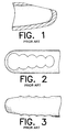
- a known design ( Figures 1-4) for improving blade efficiency is a shaver blade assembly having an outer window lying in a plane inclined to the blade axis ( Figure 1) and a dual-window inner member having inwardly facing cutting teeth (Figure 2).
- the planar form of the outer window produces a teardrop window shape having a low included angle around the window periphery, although this angle is not uniform around the periphery.
- the dual-window form of the inner may be created by, for example, a wire EDM (electrical discharge machining) process in which the wire is passed transversely to the axis through diametrically opposed portions of the cylindrical wall of the inner member. The intersection of the cylindrical outer surface and the inwardly facing wall surface thus created defines the cutting edge.
- diametrically opposed windows are formed by shaping diametrically opposed sides of the inner member.
- the radially outermost edges of the periphery of the windows thus formed in the surface of the inner tube intersect with the cylindrical surface of the tube to form the longitudinally extending inner cutting edges with teeth.
- These edges have an included angle which decreases as the distance between the edge and the tube axis increases. The sharper this edge, the easier it is to cut tissue as these inner cutting edges rotate past the outer window periphery.
- the inner window formation limits the efficiency of the tissue resection at the distal tip and does little to enable the blade to resect hard tissue such as bone.
- the wall thickness at the distal tip of the outer enables the inner cutting edge to cut only tissue which can extend past this thickness and into the outer window. Because of the need or desire for a bearing contact between the distal tips of the inner and outer members (on the axis along the inner surface) and because of the rounded tip of the inner, this design is limited in its ability to do end cutting. For example, as shown in Figures 3 and 4, the distal tip of the prior art dual-window inner member is cut flat and is spaced from the axis. Moreover, the manufacture of a tip such as this is possibly more difficult than one would desire in a production environment.
- a surgical tissue resecting instrument comprising an elongated outer tubular member, having an axis, a distal end, a proximal end and an opening at the distal end and an elongated inner tubular member axially aligned within and adapted to move within the outer tubular member.
- the inner member has a cylindrical body with a distal end, a proximal end and a cutting means at the distal end for cutting tissue presented through the opening of the outer member.
- the cutting means comprises at least two diametrically opposed finger members extending longitudinally from the distal end of the inner tubular member, each of the finger members comprising a body having a proximal portion and a distal portion.
- the proximal portion of the fingers is longitudinally extending and joined to the cylindrical body of the inner tubular member. In the preferred embodiment this proximal portion subtends a predetermined arcuate distance of less than 180° and the distal portion is joined to the proximal portion.
- the distal portion transversely and longitudinally extends from the proximal portion and terminates at a point spaced a predetermined distance from the axis. Consequently, the distal tips of the fingers are spaced from each other thus enabling the fingers to flex radially in response to excessive forces to which they may be subjected during tissue resection.
- the invention is the method of forming a shaver blade from an elongated cylindrical tube having an axis, a predetermined outer diameter and a closed, rounded end.
- the method comprises the steps of shaping the distal tip of the tube by providing a shaping means for shaping the closed, rounded end of the tube.
- the shaping means has a length greater than the tube's diameter, a width less than the tube's diameter and the method further comprises the step of shaping the distal tip of the tube by aligning the shaping means transversely to the axis of the tube and passing it axially through the distal tip of the tube.
- the shaping means is then moved proximally along a first predetermined contour, to a proximal area on the tube, and then along a second predetermined contour, symmetrical to the first predetermined contour, back to the point of entry.
- the invention is the method of resecting tissue with a surgical shaver blade assembly having an elongated inner tubular member rotatably situated within an elongated outer tubular member.
- This method comprises the steps of providing a window at the distal end of the outer tubular member and providing at least one pair of diametrically opposed fingers at the distal end of the inner tubular member, the fingers having laterally facing cutting edges.
- the method further comprises the steps of rotating the inner tubular member relative to the outer to resect tissue and enabling the fingers to flex radially in response to forces imposed on them during resection.
- Figure 1 is a cross-sectional view of the distal tip of an outer member of a prior art shaver blade assembly.
- Figure 2 is a plan view of a dual-window inner member for use with the outer member shown in Figure 1.
- Figure 3 is a side elevational view of Figure 2.
- Figure 4 is an end view of Figure 3.
- Figure 5 is a plan view of the distal tip of an inner member of a shaver blade assembly constructed in accordance with the principles of this invention.
- Figure 6 is a side elevational view of Figure 5.
- Figure 7 is an end view of Figure 6.
- Figure 8 is a front perspective view of Figure 7.
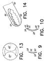
- Figure 9 is a sectional view of figure 5 taken along the line 9-9.
- Figure 10 is a sectional view of Figure 5 taken along the line 10-10.
- Figure 11 is a plan view of an alternate embodiment of the invention.
- Figure 12 is a side elevational view of Figure 11.
- Figure 13 is an end view of Figure 12.
- Figure 14 is a front perspective view of Figure 13.
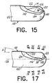
- Figure 15 is a view of the distal tip of a shaver blade assembly formed by the combination of the inner member shown in Figures 5 through 8 assembled with a representative outer member.
- Figure 16 is an end view of Figure 15.
- Figure 17 is a view of Figure 15 showing the position of the components in a different stage of operation.
- Figure 18 is an end view of Figure 17.
- Figure 19 is a sectional view of Figure 17 taken along the line 19-19.
- Figure 20 is a sectional view of Figure 17 taken along the line 20-20.
- Figure 21 is a sectional view of Figure 17 taken along the line 21-21.
- Figure 22 is a sectional view of Figure 17 taken along the line 22-22.
- FIG. 5 A detailed view of the distal tip of an inner member 14, constructed in accordance with the principles of this invention, is shown in Figures 5 through 8. It will be understood that the blade is shown removed from an associated outer tube with which it must be assembled to produce a shaver blade assembly for proper use.
- the distal tip of inner member 14 is provided with a pair of diametrically opposed, transversely arcuate fingers 20 and 22 which define an open, side and end-facing space 24 between them. Fingers 20 and 22 are symmetrical about axis 26 and are, in the preferred embodiment, integrally formed with the cylindrical body of inner member 14 and extend from the body a length L. Because of their symmetrical nature, references to one finger herein will be understood to apply to the other.
- each finger is an arcuate continuation of the cylindrical outer surface of the inner member.
- the inner surface 29 of each finger is an arcuate continuation of the inner surface of the inner member.
- the radially inwardly facing surfaces 30 and 32 of fingers 20 and 22, respectively, are also symmetrical and face each other across an imaginary axial plane intersecting axis 26. Surfaces 30 and 32 abut each other on the axis at the proximal end of space 24 and form, in effect, one continuous surface around the space although for ease of explanation it is assumed herein that each finger has a separate surface.
- the intersection of these surfaces 30 and 32 with the external cylindrical surface 34 of the inner member defines cutting edges 36 and 38, respectively.
- Each edge 36 and 38 has a curvilinear U-shaped profile (when viewed laterally as in Figure 6) having a pair of longitudinally extending edges, the distal ends of which are joined by a transversely and longitudinally extending distal edge.
- finger 20 carries a top longitudinal edge 39, a bottom longitudinal edge 40 and a distal edge 41.
- finger 22 carries a top longitudinal edge 42, a bottom longitudinal edge 43 and a distal edge 44.
- the longitudinal edges lie along the proximal, side-facing portion of each finger body while the distal edges lie along the end-facing, distal portion of the body.
- the distal edges While the longitudinal edges generally face laterally to the axis to resect tissue as the blade rotates, the distal edges have a transversely facing component near the axis to resect tissue as the blade is axially pushed against it. As will be understood below, the distal edges are separated from each other by a distal end slot 60.
- edges 36 and 38 is such that the included angle varies along their lengths and gets smaller at the distal tip. It will be understood that because of the dual-window configuration, as the inner blade rotates within the outer, only one finger and one of its corresponding edges will be active to resect tissue at any one time.
- Each finger has a proximal end 45 and a distal end 46 and each part of the fingers subtends a different arcuate distance relative to axis 26 depending upon its position along the length of inner blade 14 (as seen in Figures 9 and 10). Thus, in a plane transverse to the axis, the arcuate distance subtended by the proximal portion 45 is greater than that subtended by an intermediate portion 48.
- each finger has a contoured "hour glass" profile having its most narrow portions at area 48 and adjacent the distal tips 50 and 52 of the fingers. The large size of the proximal portion 45 provides strength and support for the relatively smaller distal tip.
- the invention includes the method of shaping a cylindrical tube to form a shaver blade.
- each finger 20, 22 may be formed at the distal tip of an inner tube having a closed, rounded end.
- a shaping means such as a wire-like member is used in the form of a wire EDM (electrical discharge machining) process or the like. In such a process the wire follows a predetermined contour (preferably programmed on a computer numerical control (CNC) machine) through diametrically opposed cylindrical wall portions of blade 14 in a direction transverse to axis 26 and perpendicular to the plane of Figure 5.
- CNC computer numerical control
- the finger formation process produces curved, sharpened distal edges 41 and 44, best seen in Figure 7. It is noted that these distal edges of each finger are tapered to a point as viewed in Figure 5, thus creating a sharper edge for endwise resection.
- All points of surfaces 30 and 32 lie in a common contour 80 which may have a variety of profiles when viewed as a projection on a plane normal to the axial plane between the fingers.
- contour 80 follows the curvilinear shape of space 24 defined by surfaces 30 and 32 as shown in Figures 5, 7 and 8. While in the preferred embodiment all the points in the surfaces lie on contour 80, it will be understood that the shape of surfaces 30 and 32 could be varied to be contoured, i.e. something other than parallel to the axial plane.
- the dual-window structure of inner member 14 may be thought of as having one window above axis 26 as viewed in Figures 6 and 7 and another window below the axis.
- the curvilinear window periphery has edges of differing included angles.
- the inner tube is sized to be rotatably received within an outer tube with little annular clearance (shown in Figure 15), the creation of distal slot 60 does not adversely affect shaver blade performance. While there is no axial bearing contact between the inner and outer members, the area around distal tips 50 and 52 is transversely extending and sufficiently large to provide adequate bearing contact between the inner and outer members. As best seen in the end view shown in Figures 14 and 15, the inner and outer members 102 and 104 overlap in the area of axis 126 in order to create a bearing contact area along a predetermined part of the proximally facing inner surface of the outer member and the transversely extending outer surface of the inner member.
- Rotation of the inner tubular member relative to the outer tubular member causes tissue resection through a shearing or scissoring action as the cutting edges of the inner and outer windows are brought into proximity.
- the low included angle of the periphery of the fingers and the distal end slot 60 cooperate to produce efficient endwise tissue resection allowing use of a single shaver for end cutting, side cutting and resection of bone as well as soft tissue.
- Inner member 60 is identical to inner member 15 except that the fingers 62 and 64 are provided with teeth 66 along portions of their periphery. Furthermore, while the teeth along finger 62 are symmetrical to their counterparts on finger 64, the profile of the teeth varies as a function of their longitudinal position.
- the proximal-most tooth 70 has a wider base than adjacent tooth 72 and the bases of teeth 74, 76 and 78 get progressively narrower toward the distal tip.
- the teeth may be irregularly shaped along the rim of the cutting edge in order to optimize the tip rake angle and root rake angle at each tooth position. Since each tooth varies in lateral position from the center line, the previously discussed wire EDM formation process easily produces varying included angles in different teeth.
- a shaver blade assembly 100 comprising an elongated outer tube 102 assembled with an elongated inner tube 14 rotatably situated within its interior and more particularly described in Figures 5 through 8.
- the proximal ends of the inner and outer tubes are conventional and do not form any part of this invention.
- a representative description of the proximal ends of shaver blade assembly 10 may be had by reference to U.S. Patent 5,411,514 (Fucci et al.), assigned to the assignee hereof and incorporated by reference herein.
- Outer tube 102 is provided at its distal end with a window 120 having a peripheral edge 122 entirely surrounded by an angled land surface 124.
- outer window 120 is considered sharpened since land 124 lies at an angle A relative to the axis 126 of the tube as more particularly described in a co-pending patent application directed to this particular structure, assigned to the assignee hereof and incorporated by reference herein.
- the cutting windows of the inner member face not only endwise as shown in Figure 16 but laterally as shown in Figure 15. That is, at any given point during the rotary motion of the inner member in a given direction the particular inner edge which is active at the time, for example edge 38, will intersect the outer edge 122 at two points: a point 140 along the laterally facing portion of window 20 ( Figure 15) and a point 150 along the end facing portion of the blade as shown in Figure 16.
- the trailing edge will be understood to be inactive since it will face in a direction opposite to the direction of rotation.
- the active edge will intersect outer edge 122 of the outer member at varying angles depending upon the position of the inner member.
- edge 38 intersects edge 122 at points 140 and 150 while at a subsequent time, as the inner member rotates within the outer member, edge 38 intersects edge 122 at points 142 and 152 shown in Figure 17.
- the angles between the edges at these points vary and the variation in this angle of attack facilitates the cooperative shearing action of the two cutting edges 38 and 122 along the periphery of outer window 120.
- FIG. 19 through 22 A representative set of cross-sections of the inner and outer windows is shown in Figures 19 through 22. The various views are taken along the respectively numbered lines in Figure 17, although only the portions of the tubes immediately adjacent the edges are shown. It will be noted that the included angles of inner and outer edges at the points represented by Figures 19 and 20 are relatively sharp although the sharpness is greater at the point represented by Figure 21. The point represented by Figure 22 is approximately the same as point 150, thus demonstrating that the present invention provides a device capable of sharp edges on end facing cuts.
- the fingers may be formed separately from the body of the inner member and subsequently attached. Also, the fingers need not necessarily have arcuate outer surfaces aligned with the cylindrical outer surface of the inner member.
- Another configuration may employ a rotatable shaft having affixed to one end a cutting tip in the form of the fingers.
Landscapes
- Health & Medical Sciences (AREA)
- Surgery (AREA)
- Life Sciences & Earth Sciences (AREA)
- Medical Informatics (AREA)
- Nuclear Medicine, Radiotherapy & Molecular Imaging (AREA)
- Engineering & Computer Science (AREA)
- Biomedical Technology (AREA)
- Heart & Thoracic Surgery (AREA)
- Orthopedic Medicine & Surgery (AREA)
- Molecular Biology (AREA)
- Animal Behavior & Ethology (AREA)
- General Health & Medical Sciences (AREA)
- Public Health (AREA)
- Veterinary Medicine (AREA)
- Surgical Instruments (AREA)
- Knives (AREA)
Applications Claiming Priority (2)
| Application Number | Priority Date | Filing Date | Title |
|---|---|---|---|
| US631714 | 1996-04-10 | ||
| US08/631,714 US5766199A (en) | 1996-04-10 | 1996-04-10 | Endoscopic shaver blade with resilient cutting edges |
Publications (2)
| Publication Number | Publication Date |
|---|---|
| EP0800794A1 true EP0800794A1 (fr) | 1997-10-15 |
| EP0800794B1 EP0800794B1 (fr) | 2004-12-01 |
Family
ID=24532421
Family Applications (1)
| Application Number | Title | Priority Date | Filing Date |
|---|---|---|---|
| EP97201072A Expired - Lifetime EP0800794B1 (fr) | 1996-04-10 | 1997-04-10 | Lame de rasage endoscopique avec des tranchants résilients |
Country Status (7)
| Country | Link |
|---|---|
| US (2) | US5766199A (fr) |
| EP (1) | EP0800794B1 (fr) |
| JP (1) | JPH1028692A (fr) |
| AT (1) | ATE283668T1 (fr) |
| AU (1) | AU730317B2 (fr) |
| CA (1) | CA2202113C (fr) |
| DE (1) | DE69731786T2 (fr) |
Cited By (3)
| Publication number | Priority date | Publication date | Assignee | Title |
|---|---|---|---|---|
| EP2455115A1 (fr) * | 2010-11-19 | 2012-05-23 | Persat, Jean-Charles | Vecteur de prélèvement pour tissus en particulier adipeux |
| WO2013066614A1 (fr) * | 2011-10-31 | 2013-05-10 | Bausch & Lomb Incorporated | Ensemble de tubes pour un élément de coupe rotatif de tissu ayant une lame interne incurvée |
| US8574254B2 (en) | 2011-01-25 | 2013-11-05 | Smith & Nephew, Inc. | Arthroscopic cutting blade |
Families Citing this family (91)
| Publication number | Priority date | Publication date | Assignee | Title |
|---|---|---|---|---|
| US6156049A (en) * | 1997-04-11 | 2000-12-05 | Coherent Inc. | Method and apparatus for transurethral resection of the prostate |
| NL1006944C2 (nl) | 1997-09-04 | 1999-03-11 | Mark Hans Emanuel | Chirurgische endoscopische snij-inrichting. |
| US6217598B1 (en) * | 1997-11-25 | 2001-04-17 | Linvatec Corporation | End-cutting shaver blade |
| US5980547A (en) * | 1998-10-26 | 1999-11-09 | Beere Precision Medical Instruments, Inc. | Rotary cutter |
| US6530929B1 (en) * | 1999-10-20 | 2003-03-11 | Sdgi Holdings, Inc. | Instruments for stabilization of bony structures |
| US6419684B1 (en) * | 2000-05-16 | 2002-07-16 | Linvatec Corporation | End-cutting shaver blade for axial resection |
| US6544271B1 (en) * | 2000-07-18 | 2003-04-08 | Scimed Life Systems, Inc. | Device for full-thickness resectioning of an organ |
| US6503263B2 (en) | 2000-09-24 | 2003-01-07 | Medtronic, Inc. | Surgical micro-shaving instrument with elevator tip |
| US7171884B2 (en) * | 2001-10-25 | 2007-02-06 | De Torre Robert P | Resilient cutting blades and cutting devices |
| US7226459B2 (en) | 2001-10-26 | 2007-06-05 | Smith & Nephew, Inc. | Reciprocating rotary arthroscopic surgical instrument |
| US7641667B2 (en) * | 2002-01-29 | 2010-01-05 | Smith & Nephew, Inc. | Tissue cutting instrument |
| US7361181B2 (en) * | 2002-10-04 | 2008-04-22 | St. Jude Medical Atg, Inc. | Apparatus and methods for creating anastomoses |
| US8469993B2 (en) | 2003-06-18 | 2013-06-25 | Boston Scientific Scimed, Inc. | Endoscopic instruments |
| US20040260337A1 (en) * | 2003-06-18 | 2004-12-23 | Scimed Life Systems, Inc. | Endoscopic instruments and methods of manufacture |
| US7785337B2 (en) * | 2003-09-09 | 2010-08-31 | Medtronic Xomed, Inc. | Surgical micro-burring instrument and method of performing sinus surgery |
| US7549993B2 (en) * | 2004-06-16 | 2009-06-23 | Warsaw Orthopedic, Inc. | Constant lift cam spreader |
| CH700185B1 (de) * | 2004-07-22 | 2010-07-15 | Orlando Da Rold | Chirurgisches Schneidinstrument. |
| US8062214B2 (en) | 2004-08-27 | 2011-11-22 | Smith & Nephew, Inc. | Tissue resecting system |
| US20060212060A1 (en) | 2005-02-11 | 2006-09-21 | Arthrex, Inc. | Arthroscopic shaver and method of manufacturing same |
| US20060196038A1 (en) * | 2005-03-02 | 2006-09-07 | Van Wyk Robert A | Arthroscopic shaver with two pass inner blade and method of manufacturing same |
| US20160001064A1 (en) * | 2005-07-22 | 2016-01-07 | The Spectranetics Corporation | Endocardial lead cutting apparatus |
| US20090031871A1 (en) * | 2006-06-08 | 2009-02-05 | Malandain Hugues F | Dual cutting element tool for debulking bone |
| US20080021559A1 (en) * | 2006-07-06 | 2008-01-24 | Lanx, Llc | Expandable spinal fusion cage |
| US7771473B2 (en) * | 2006-07-06 | 2010-08-10 | Lanx, Inc. | Expandable spinal fusion cage |
| US7666200B2 (en) * | 2006-07-19 | 2010-02-23 | Target Medical Innovations Llc | Endoscopic cutting instrument with axial and rotary motion |
| US8177803B2 (en) * | 2006-07-19 | 2012-05-15 | Target Medical Innovations, LLC | Endoscopic cutting instruments having improved cutting efficiency and reduced manufacturing costs |
| US7909841B1 (en) | 2006-09-28 | 2011-03-22 | Nelson Chris L | Co-axial actuated scissors |
| US20100286477A1 (en) * | 2009-05-08 | 2010-11-11 | Ouyang Xiaolong | Internal tissue visualization system comprising a rf-shielded visualization sensor module |
| US20080119759A1 (en) * | 2006-11-21 | 2008-05-22 | The Cleveland Clinic Foundation | Method and apparatus for aspirating bone marrow |
| US20100030216A1 (en) * | 2008-07-30 | 2010-02-04 | Arcenio Gregory B | Discectomy tool having counter-rotating nucleus disruptors |
| US20100121142A1 (en) * | 2008-11-12 | 2010-05-13 | Ouyang Xiaolong | Minimally Invasive Imaging Device |
| US20100121139A1 (en) * | 2008-11-12 | 2010-05-13 | Ouyang Xiaolong | Minimally Invasive Imaging Systems |
| US20100121155A1 (en) * | 2008-11-12 | 2010-05-13 | Ouyang Xiaolong | Minimally Invasive Tissue Modification Systems With Integrated Visualization |
| US8070765B2 (en) | 2009-01-28 | 2011-12-06 | Medtronic Xomed, Inc. | Systems and methods for surgical removal of brain tumors |
| US8435259B2 (en) * | 2009-05-19 | 2013-05-07 | Stryker Corporation | Surgical tool arrangement and surgical cutting accessory for use therewith with the tool arrangement including a toothed cutting edge and a generally straight cutting edge |
| US9155454B2 (en) | 2010-09-28 | 2015-10-13 | Smith & Nephew, Inc. | Hysteroscopic system |
| US9445825B2 (en) | 2011-02-10 | 2016-09-20 | Wright Medical Technology, Inc. | Expandable surgical device |
| US9119659B2 (en) | 2011-12-03 | 2015-09-01 | Ouroboros Medical, Inc. | Safe cutting heads and systems for fast removal of a target tissue |
| US9161774B2 (en) | 2013-03-14 | 2015-10-20 | Kyphon Sarl | Rotatable cutting instrument |
| US9839441B2 (en) | 2013-03-14 | 2017-12-12 | Stryker Corporation | Surgical tool arrangement and surgical cutting accessory for use therewith |
| US9636131B2 (en) | 2013-03-15 | 2017-05-02 | Stryker Corporation | Surgical tool arrangement and surgical cutting accessory for use therewith |
| KR20160040226A (ko) | 2013-07-19 | 2016-04-12 | 아우로보로스 메디컬, 아이엔씨 | 진공-보조된, 조직 제거 시스템을 위한 막힘 방지 장치 |
| US9370295B2 (en) | 2014-01-13 | 2016-06-21 | Trice Medical, Inc. | Fully integrated, disposable tissue visualization device |
| US10342579B2 (en) | 2014-01-13 | 2019-07-09 | Trice Medical, Inc. | Fully integrated, disposable tissue visualization device |
| US11547446B2 (en) | 2014-01-13 | 2023-01-10 | Trice Medical, Inc. | Fully integrated, disposable tissue visualization device |
| US20150223831A1 (en) * | 2014-02-12 | 2015-08-13 | Arthrex, Inc. | Surgical shaver assembly |
| EP3131479B1 (fr) | 2014-04-17 | 2019-04-10 | Stryker Corporation | Outil chirurgical à arbre sélectivement flexible, qui résiste à la déformation |
| US20160066945A1 (en) * | 2014-09-08 | 2016-03-10 | Medtronic-Xomed, Inc. | Tumor margin device |
| US9737322B2 (en) | 2014-09-08 | 2017-08-22 | Medtronic Xomed, Inc. | Method for resection of tumors and tissues |
| US10470786B2 (en) | 2014-10-16 | 2019-11-12 | Stryker Corporation | Surgical tool arrangement and surgical cutting accessory for use therewith |
| WO2016100522A1 (fr) | 2014-12-16 | 2016-06-23 | Smith & Nephew, Inc. | Dispositif chirurgical avec système d'extraction tissulaire incorporé |
| WO2016122500A1 (fr) | 2015-01-28 | 2016-08-04 | Smith & Nephew, Inc. | Système de résection de tissu |
| WO2016191422A1 (fr) | 2015-05-26 | 2016-12-01 | Covidien Lp | Systèmes et procédés pour la génération d'un palier fluide pour une procédure de fonctionnement |
| US10804769B2 (en) | 2015-06-17 | 2020-10-13 | Covidien Lp | Surgical instrument with phase change cooling |
| WO2016205126A1 (fr) | 2015-06-17 | 2016-12-22 | Covidien Lp | Dispositif endoscopique avec bride de goutte-à-goutte et procédés d'utilisation pour une procédure de fonctionnement |
| CA2989162A1 (fr) | 2015-06-18 | 2016-12-22 | Covidien Lp | Instrument chirurgical avec commande d'aspiration |
| CN108024695B (zh) | 2015-08-11 | 2021-05-04 | 特里斯医疗有限公司 | 完全集成的一次性组织可视化装置 |
| US11864735B2 (en) | 2016-05-26 | 2024-01-09 | Covidien Lp | Continuous flow endoscope |
| EP4005512B1 (fr) | 2016-07-14 | 2024-08-14 | Stryker European Operations Holdings LLC | Ensemble de coupe pour un instrument chirurgical doté d'un ensemble d'entraînement |
| US10299819B2 (en) | 2016-07-28 | 2019-05-28 | Covidien Lp | Reciprocating rotary surgical cutting device and system for tissue resecting, and method for its use |
| US10299803B2 (en) | 2016-08-04 | 2019-05-28 | Covidien Lp | Self-aligning drive coupler |
| US10772654B2 (en) | 2017-03-02 | 2020-09-15 | Covidien Lp | Fluid-driven tissue resecting instruments, systems, and methods |
| EP4173579B1 (fr) | 2017-08-02 | 2024-06-19 | Stryker Corporation | Systèmes d'outil chirurgical |
| US10869684B2 (en) | 2018-02-13 | 2020-12-22 | Covidien Lp | Powered tissue resecting device |
| WO2019191705A1 (fr) | 2018-03-29 | 2019-10-03 | Trice Medical, Inc. | Endoscope entièrement intégré ayant des capacités de biopsie et procédés d'utilisation |
| US11547815B2 (en) | 2018-05-30 | 2023-01-10 | Covidien Lp | Systems and methods for measuring and controlling pressure within an internal body cavity |
| US11065147B2 (en) | 2018-10-18 | 2021-07-20 | Covidien Lp | Devices, systems, and methods for pre-heating fluid to be introduced into a patient during a surgical procedure |
| US11197710B2 (en) | 2018-10-26 | 2021-12-14 | Covidien Lp | Tissue resecting device including a blade lock and release mechanism |
| US11083481B2 (en) | 2019-02-22 | 2021-08-10 | Covidien Lp | Tissue resecting instrument including an outflow control seal |
| US11154318B2 (en) | 2019-02-22 | 2021-10-26 | Covidien Lp | Tissue resecting instrument including an outflow control seal |
| US10898218B2 (en) | 2019-02-25 | 2021-01-26 | Covidien Lp | Tissue resecting device including a motor cooling assembly |
| US10945752B2 (en) | 2019-03-20 | 2021-03-16 | Covidien Lp | Tissue resecting instrument including a rotation lock feature |
| US11883058B2 (en) | 2019-03-26 | 2024-01-30 | Covidien Lp | Jaw members, end effector assemblies, and ultrasonic surgical instruments including the same |
| US11129672B2 (en) | 2019-04-04 | 2021-09-28 | Covidien Lp | Tissue resecting device including an articulatable cutting member |
| CN113840578B (zh) | 2019-05-29 | 2024-06-18 | 柯惠有限合伙公司 | 用于管理患者体液的宫腔镜检查系统和方法 |
| US11452806B2 (en) | 2019-10-04 | 2022-09-27 | Covidien Lp | Outflow collection vessels, systems, and components thereof for hysteroscopic surgical procedures |
| US11890237B2 (en) | 2019-10-04 | 2024-02-06 | Covidien Lp | Outflow collection vessels, systems, and components thereof for hysteroscopic surgical procedures |
| CN114599298A (zh) * | 2019-11-20 | 2022-06-07 | 史密夫和内修有限公司 | 机械切除刀片 |
| US11376032B2 (en) | 2019-12-05 | 2022-07-05 | Covidien Lp | Tissue resecting instrument |
| US11179172B2 (en) | 2019-12-05 | 2021-11-23 | Covidien Lp | Tissue resecting instrument |
| US11547782B2 (en) | 2020-01-31 | 2023-01-10 | Covidien Lp | Fluid collecting sheaths for endoscopic devices and systems |
| US11737777B2 (en) | 2020-02-05 | 2023-08-29 | Covidien Lp | Tissue resecting instruments |
| US11317947B2 (en) | 2020-02-18 | 2022-05-03 | Covidien Lp | Tissue resecting instrument |
| US11744605B2 (en) | 2020-03-31 | 2023-09-05 | Covidien Lp | Tissue resecting device with deflectable tip |
| US11596429B2 (en) | 2020-04-20 | 2023-03-07 | Covidien Lp | Tissue resecting instrument |
| US12156673B2 (en) | 2020-10-07 | 2024-12-03 | Covidien Lp | Temperature measurement device for a handpiece of a surgical instrument |
| US11571233B2 (en) | 2020-11-19 | 2023-02-07 | Covidien Lp | Tissue removal handpiece with integrated suction |
| WO2022159568A1 (fr) | 2021-01-20 | 2022-07-28 | Mako Surgical Corp. | Méthodes et systèmes à instrument chirurgical robotique à main |
| US12364500B2 (en) | 2021-05-26 | 2025-07-22 | Covidien Lp | Tissue resecting instrument |
| US12303109B2 (en) | 2021-12-22 | 2025-05-20 | Covidien Lp | Surgical systems and methods for component cooling while warming fluid to be introduced during a surgical procedure |
| US12478359B2 (en) | 2022-09-13 | 2025-11-25 | Covidien Lp | Surgical instruments and manufacturing methods facilitating durable engagement between components of different materials |
Citations (5)
| Publication number | Priority date | Publication date | Assignee | Title |
|---|---|---|---|---|
| EP0276478A1 (fr) * | 1986-12-30 | 1988-08-03 | SMITH & NEPHEW DYONICS, INC. | Appareil chirurgical arthroscopique |
| US5112299A (en) * | 1989-10-25 | 1992-05-12 | Hall Surgical Division Of Zimmer, Inc. | Arthroscopic surgical apparatus and method |
| US5123904A (en) * | 1988-04-28 | 1992-06-23 | Olympus Optical Co., Ltd. | Surgical resecting instrument |
| WO1992015255A1 (fr) * | 1991-03-06 | 1992-09-17 | Bowen & Co., Inc. | Procede et instrument d'elimination de matiere |
| US5366468A (en) * | 1993-11-09 | 1994-11-22 | Linvatec Corporation | Double bladed surgical router having aspiration ports within flutes |
Family Cites Families (18)
| Publication number | Priority date | Publication date | Assignee | Title |
|---|---|---|---|---|
| US3732858A (en) * | 1968-09-16 | 1973-05-15 | Surgical Design Corp | Apparatus for removing blood clots, cataracts and other objects from the eye |
| US3844272A (en) * | 1969-02-14 | 1974-10-29 | A Banko | Surgical instruments |
| US3882872A (en) * | 1970-01-05 | 1975-05-13 | Nicholas G Douvas | Method and apparatus for cataract surgery |
| US3945375A (en) * | 1972-04-04 | 1976-03-23 | Surgical Design Corporation | Rotatable surgical instrument |
| US4167943A (en) * | 1977-06-27 | 1979-09-18 | Surgical Design Corp. | Blade type rotatable surgical cutting instrument with improved cutter blade wear |
| US4274414A (en) * | 1979-02-21 | 1981-06-23 | Dyonics, Inc. | Surgical instrument |
| DE3347671A1 (de) * | 1983-12-31 | 1985-07-11 | Richard Wolf Gmbh, 7134 Knittlingen | Instrument zur entnahme von gewebeproben |
| US4649919A (en) * | 1985-01-23 | 1987-03-17 | Precision Surgical Instruments, Inc. | Surgical instrument |
| US4850354A (en) * | 1987-08-13 | 1989-07-25 | Baxter Travenol Laboratories, Inc. | Surgical cutting instrument |
| US4819635A (en) * | 1987-09-18 | 1989-04-11 | Henry Shapiro | Tubular microsurgery cutting apparatus |
| US4844088A (en) * | 1987-12-11 | 1989-07-04 | Parviz Kambin | Surgical cutting device with reciprocating cutting member |
| US5007917A (en) * | 1990-03-08 | 1991-04-16 | Stryker Corporation | Single blade cutter for arthroscopic surgery |
| EP0544769B1 (fr) * | 1990-08-20 | 1998-03-04 | SASTRI, Suri A. | Instruments tubulaires chirurgicaux coupants |
| US5286253A (en) * | 1992-10-09 | 1994-02-15 | Linvatec Corporation | Angled rotating surgical instrument |
| US5456689A (en) * | 1993-10-13 | 1995-10-10 | Arnold J. Kresch | Method and device for tissue resection |
| US5423844A (en) * | 1993-10-22 | 1995-06-13 | Promex, Inc. | Rotary surgical cutting instrument |
| US5437630A (en) * | 1993-10-27 | 1995-08-01 | Stryker Corporation | Arthroscopic cutter having curved rotatable drive |
| US5489291A (en) * | 1994-02-23 | 1996-02-06 | Wiley; Roy C. | Apparatus for removing tissue during surgical procedures |
-
1996
- 1996-04-10 US US08/631,714 patent/US5766199A/en not_active Expired - Lifetime
-
1997
- 1997-03-20 AU AU16399/97A patent/AU730317B2/en not_active Expired
- 1997-04-08 CA CA002202113A patent/CA2202113C/fr not_active Expired - Lifetime
- 1997-04-10 DE DE69731786T patent/DE69731786T2/de not_active Expired - Lifetime
- 1997-04-10 JP JP9092033A patent/JPH1028692A/ja active Pending
- 1997-04-10 AT AT97201072T patent/ATE283668T1/de not_active IP Right Cessation
- 1997-04-10 EP EP97201072A patent/EP0800794B1/fr not_active Expired - Lifetime
-
1998
- 1998-04-01 US US09/053,458 patent/US6001116A/en not_active Expired - Lifetime
Patent Citations (5)
| Publication number | Priority date | Publication date | Assignee | Title |
|---|---|---|---|---|
| EP0276478A1 (fr) * | 1986-12-30 | 1988-08-03 | SMITH & NEPHEW DYONICS, INC. | Appareil chirurgical arthroscopique |
| US5123904A (en) * | 1988-04-28 | 1992-06-23 | Olympus Optical Co., Ltd. | Surgical resecting instrument |
| US5112299A (en) * | 1989-10-25 | 1992-05-12 | Hall Surgical Division Of Zimmer, Inc. | Arthroscopic surgical apparatus and method |
| WO1992015255A1 (fr) * | 1991-03-06 | 1992-09-17 | Bowen & Co., Inc. | Procede et instrument d'elimination de matiere |
| US5366468A (en) * | 1993-11-09 | 1994-11-22 | Linvatec Corporation | Double bladed surgical router having aspiration ports within flutes |
Cited By (5)
| Publication number | Priority date | Publication date | Assignee | Title |
|---|---|---|---|---|
| EP2455115A1 (fr) * | 2010-11-19 | 2012-05-23 | Persat, Jean-Charles | Vecteur de prélèvement pour tissus en particulier adipeux |
| FR2967567A1 (fr) * | 2010-11-19 | 2012-05-25 | Jean-Charles Persat | Vecteur de prelevement pour tissus en particulier adipeux |
| US8858461B2 (en) | 2010-11-19 | 2014-10-14 | Jean-Charles Persat | Tissue sampling tool, in particular for adipose tissue |
| US8574254B2 (en) | 2011-01-25 | 2013-11-05 | Smith & Nephew, Inc. | Arthroscopic cutting blade |
| WO2013066614A1 (fr) * | 2011-10-31 | 2013-05-10 | Bausch & Lomb Incorporated | Ensemble de tubes pour un élément de coupe rotatif de tissu ayant une lame interne incurvée |
Also Published As
| Publication number | Publication date |
|---|---|
| AU730317B2 (en) | 2001-03-01 |
| US5766199A (en) | 1998-06-16 |
| CA2202113A1 (fr) | 1997-10-10 |
| EP0800794B1 (fr) | 2004-12-01 |
| DE69731786D1 (de) | 2005-01-05 |
| AU1639997A (en) | 1997-10-16 |
| JPH1028692A (ja) | 1998-02-03 |
| US6001116A (en) | 1999-12-14 |
| DE69731786T2 (de) | 2005-04-28 |
| ATE283668T1 (de) | 2004-12-15 |
| CA2202113C (fr) | 2005-11-15 |
Similar Documents
| Publication | Publication Date | Title |
|---|---|---|
| CA2202113C (fr) | Lame de rasoir endoscopique munie de tranchants resistants | |
| US6217598B1 (en) | End-cutting shaver blade | |
| US6419684B1 (en) | End-cutting shaver blade for axial resection | |
| US5843106A (en) | Endoscopic shaver blade with sharp outer edge | |
| CA2658255C (fr) | Instrument de decoupe endoscopique avec mouvement axial et rotatif | |
| EP3868314B1 (fr) | Instrument de coupe chirurgical avec capacité d'aspiration distale | |
| EP0807413B1 (fr) | Instrument pour réaliser des lipectomies ouvertes ou endoscopiques | |
| EP0500146B1 (fr) | Appareil chirurgical arthroscopique | |
| AU722524B2 (en) | Surgical instrument | |
| US5007917A (en) | Single blade cutter for arthroscopic surgery | |
| US4811734A (en) | Surgical cutting instrument | |
| US5964777A (en) | Surgical cutting instrument | |
| US9622756B2 (en) | Arthroscopic resection methods | |
| EP1690504A1 (fr) | Appareil de résection arthroscipique et son procédé de fabrication | |
| EP1958576A2 (fr) | Rasoir double coupe | |
| EP0384735A1 (fr) | Instrument chirurgical coupant | |
| CA2060758A1 (fr) | Instrument chirurgical pour pratiquer des incisions | |
| EP1972288A1 (fr) | Lame de rasoir avec marquages de profondeur | |
| AU2004271977A1 (en) | Surgical micro-burring instrument and method of performing sinus surgery | |
| EP1698290A1 (fr) | Moyen de résection arthroscopique avec lame intérieure à deux pas et méthode de fabrication | |
| WO2004069498A2 (fr) | Systeme de manipulation et de coupe et procede associe | |
| WO2004073531A2 (fr) | Ensemble de lame chirurgicale de forme allongee avec organe interne interchangeable, trousse et procede associes | |
| WO2001022890A1 (fr) | Conception de retenue d'outil chirurgical pour instruments chirurgicaux |
Legal Events
| Date | Code | Title | Description |
|---|---|---|---|
| PUAI | Public reference made under article 153(3) epc to a published international application that has entered the european phase |
Free format text: ORIGINAL CODE: 0009012 |
|
| AK | Designated contracting states |
Kind code of ref document: A1 Designated state(s): AT BE CH DE ES FR GB GR IE IT LI LU NL SE |
|
| RAP1 | Party data changed (applicant data changed or rights of an application transferred) |
Owner name: LINVATEC CORPORATION |
|
| 17P | Request for examination filed |
Effective date: 19980415 |
|
| 17Q | First examination report despatched |
Effective date: 20020219 |
|
| GRAP | Despatch of communication of intention to grant a patent |
Free format text: ORIGINAL CODE: EPIDOSNIGR1 |
|
| GRAS | Grant fee paid |
Free format text: ORIGINAL CODE: EPIDOSNIGR3 |
|
| GRAA | (expected) grant |
Free format text: ORIGINAL CODE: 0009210 |
|
| RBV | Designated contracting states (corrected) |
Designated state(s): AT BE CH DE DK ES FR GB GR IE IT LI LU NL SE |
|
| AK | Designated contracting states |
Kind code of ref document: B1 Designated state(s): AT BE CH DE DK ES FR GB GR IE IT LI LU NL SE |
|
| PG25 | Lapsed in a contracting state [announced via postgrant information from national office to epo] |
Ref country code: NL Free format text: LAPSE BECAUSE OF FAILURE TO SUBMIT A TRANSLATION OF THE DESCRIPTION OR TO PAY THE FEE WITHIN THE PRESCRIBED TIME-LIMIT Effective date: 20041201 Ref country code: LI Free format text: LAPSE BECAUSE OF FAILURE TO SUBMIT A TRANSLATION OF THE DESCRIPTION OR TO PAY THE FEE WITHIN THE PRESCRIBED TIME-LIMIT Effective date: 20041201 Ref country code: ES Free format text: LAPSE BECAUSE OF FAILURE TO SUBMIT A TRANSLATION OF THE DESCRIPTION OR TO PAY THE FEE WITHIN THE PRESCRIBED TIME-LIMIT Effective date: 20041201 Ref country code: CH Free format text: LAPSE BECAUSE OF FAILURE TO SUBMIT A TRANSLATION OF THE DESCRIPTION OR TO PAY THE FEE WITHIN THE PRESCRIBED TIME-LIMIT Effective date: 20041201 Ref country code: BE Free format text: LAPSE BECAUSE OF FAILURE TO SUBMIT A TRANSLATION OF THE DESCRIPTION OR TO PAY THE FEE WITHIN THE PRESCRIBED TIME-LIMIT Effective date: 20041201 Ref country code: AT Free format text: LAPSE BECAUSE OF FAILURE TO SUBMIT A TRANSLATION OF THE DESCRIPTION OR TO PAY THE FEE WITHIN THE PRESCRIBED TIME-LIMIT Effective date: 20041201 |
|
| REG | Reference to a national code |
Ref country code: GB Ref legal event code: FG4D |
|
| REG | Reference to a national code |
Ref country code: CH Ref legal event code: EP |
|
| REG | Reference to a national code |
Ref country code: IE Ref legal event code: FG4D |
|
| REF | Corresponds to: |
Ref document number: 69731786 Country of ref document: DE Date of ref document: 20050105 Kind code of ref document: P |
|
| PG25 | Lapsed in a contracting state [announced via postgrant information from national office to epo] |
Ref country code: SE Free format text: LAPSE BECAUSE OF FAILURE TO SUBMIT A TRANSLATION OF THE DESCRIPTION OR TO PAY THE FEE WITHIN THE PRESCRIBED TIME-LIMIT Effective date: 20050301 Ref country code: GR Free format text: LAPSE BECAUSE OF FAILURE TO SUBMIT A TRANSLATION OF THE DESCRIPTION OR TO PAY THE FEE WITHIN THE PRESCRIBED TIME-LIMIT Effective date: 20050301 Ref country code: DK Free format text: LAPSE BECAUSE OF FAILURE TO SUBMIT A TRANSLATION OF THE DESCRIPTION OR TO PAY THE FEE WITHIN THE PRESCRIBED TIME-LIMIT Effective date: 20050301 |
|
| PGFP | Annual fee paid to national office [announced via postgrant information from national office to epo] |
Ref country code: DK Payment date: 20050314 Year of fee payment: 9 |
|
| PGFP | Annual fee paid to national office [announced via postgrant information from national office to epo] |
Ref country code: NL Payment date: 20050316 Year of fee payment: 9 |
|
| NLV1 | Nl: lapsed or annulled due to failure to fulfill the requirements of art. 29p and 29m of the patents act | ||
| REG | Reference to a national code |
Ref country code: CH Ref legal event code: PL |
|
| PLBE | No opposition filed within time limit |
Free format text: ORIGINAL CODE: 0009261 |
|
| STAA | Information on the status of an ep patent application or granted ep patent |
Free format text: STATUS: NO OPPOSITION FILED WITHIN TIME LIMIT |
|
| ET | Fr: translation filed | ||
| 26N | No opposition filed |
Effective date: 20050902 |
|
| PGFP | Annual fee paid to national office [announced via postgrant information from national office to epo] |
Ref country code: IT Payment date: 20060430 Year of fee payment: 10 |
|
| PG25 | Lapsed in a contracting state [announced via postgrant information from national office to epo] |
Ref country code: IT Free format text: LAPSE BECAUSE OF NON-PAYMENT OF DUE FEES Effective date: 20070410 |
|
| REG | Reference to a national code |
Ref country code: FR Ref legal event code: PLFP Year of fee payment: 19 |
|
| PGFP | Annual fee paid to national office [announced via postgrant information from national office to epo] |
Ref country code: IE Payment date: 20150330 Year of fee payment: 19 |
|
| PGFP | Annual fee paid to national office [announced via postgrant information from national office to epo] |
Ref country code: LU Payment date: 20150417 Year of fee payment: 19 Ref country code: GB Payment date: 20150325 Year of fee payment: 19 |
|
| PGFP | Annual fee paid to national office [announced via postgrant information from national office to epo] |
Ref country code: DE Payment date: 20150429 Year of fee payment: 19 |
|
| PGFP | Annual fee paid to national office [announced via postgrant information from national office to epo] |
Ref country code: FR Payment date: 20150325 Year of fee payment: 19 |
|
| REG | Reference to a national code |
Ref country code: DE Ref legal event code: R119 Ref document number: 69731786 Country of ref document: DE |
|
| GBPC | Gb: european patent ceased through non-payment of renewal fee |
Effective date: 20160410 |
|
| PG25 | Lapsed in a contracting state [announced via postgrant information from national office to epo] |
Ref country code: LU Free format text: LAPSE BECAUSE OF NON-PAYMENT OF DUE FEES Effective date: 20160410 |
|
| REG | Reference to a national code |
Ref country code: IE Ref legal event code: MM4A |
|
| REG | Reference to a national code |
Ref country code: FR Ref legal event code: ST Effective date: 20161230 |
|
| PG25 | Lapsed in a contracting state [announced via postgrant information from national office to epo] |
Ref country code: DE Free format text: LAPSE BECAUSE OF NON-PAYMENT OF DUE FEES Effective date: 20161101 Ref country code: FR Free format text: LAPSE BECAUSE OF NON-PAYMENT OF DUE FEES Effective date: 20160502 Ref country code: GB Free format text: LAPSE BECAUSE OF NON-PAYMENT OF DUE FEES Effective date: 20160410 |
|
| PG25 | Lapsed in a contracting state [announced via postgrant information from national office to epo] |
Ref country code: IE Free format text: LAPSE BECAUSE OF NON-PAYMENT OF DUE FEES Effective date: 20160410 |