EP0800942A1 - Rechauffeur a liquide visqueux a capacite variable - Google Patents
Rechauffeur a liquide visqueux a capacite variable Download PDFInfo
- Publication number
- EP0800942A1 EP0800942A1 EP96935522A EP96935522A EP0800942A1 EP 0800942 A1 EP0800942 A1 EP 0800942A1 EP 96935522 A EP96935522 A EP 96935522A EP 96935522 A EP96935522 A EP 96935522A EP 0800942 A1 EP0800942 A1 EP 0800942A1
- Authority
- EP
- European Patent Office
- Prior art keywords
- chamber
- heat
- viscous heater
- variable capacity
- capacity type
- Prior art date
- Legal status (The legal status is an assumption and is not a legal conclusion. Google has not performed a legal analysis and makes no representation as to the accuracy of the status listed.)
- Granted
Links
Images












Classifications
-
- F—MECHANICAL ENGINEERING; LIGHTING; HEATING; WEAPONS; BLASTING
- F24—HEATING; RANGES; VENTILATING
- F24V—COLLECTION, PRODUCTION OR USE OF HEAT NOT OTHERWISE PROVIDED FOR
- F24V40/00—Production or use of heat resulting from internal friction of moving fluids or from friction between fluids and moving bodies
-
- B—PERFORMING OPERATIONS; TRANSPORTING
- B60—VEHICLES IN GENERAL
- B60H—ARRANGEMENTS OF HEATING, COOLING, VENTILATING OR OTHER AIR-TREATING DEVICES SPECIALLY ADAPTED FOR PASSENGER OR GOODS SPACES OF VEHICLES
- B60H1/00—Heating, cooling or ventilating devices
- B60H1/02—Heating, cooling or ventilating devices the heat being derived from the propulsion plant
- B60H1/04—Heating, cooling or ventilating devices the heat being derived from the propulsion plant from cooling liquid of the plant
- B60H1/08—Heating, cooling or ventilating devices the heat being derived from the propulsion plant from cooling liquid of the plant from other radiator than main radiator
Definitions
- the present invention relates to a variable capacity type viscous heater in which a viscous fluid is caused to generate heat by shearing. The resulting heat is utilized as a thermal source for heating by carrying out heat exchange with a circulating fluid which circulates in a radiator chamber.
- Japanese Unexamined Patent Publication (KOKAI) No. 3-98,107 discloses a variable capacity type viscous heater.
- a front housing and a rear housing are disposed and fastened so as to face with each other, and form a heat-generating chamber and a water jacket therein.
- the water jacket is disposed around an outer region of the heat-generating chamber.
- circulating water is circulated so that it is taken in through a water inlet port, and that it is delivered out to an external heating circuit through a water outlet port.
- a driving shaft is held rotatably via a bearing apparatus.
- a rotor is fixed so that it can rotate in the heat-generating chamber.
- a wall surface of the heat-generating chamber and an outer surface of the rotor constitute axial labyrinth grooves which approach to each other.
- a viscous fluid such as a silicone oil
- the characteristic arrangements of the viscous heater are as follows: An upper cover and a lower cover, which are provided with a diaphragm therein, are disposed below the front and rear housings.
- a control chamber is defined by the upper cover and the diaphragm.
- the heat-generating chamber is communicated with the atmosphere by a through hole which is drilled through at the top end of the front and rear housings, and the heat-generating chamber is also communicated with the control chamber by a communication pipe which is disposed in the upper cover.
- the diaphragm is capable of adjusting the internal volume of the control chamber by means of a manifold negative pressure, a coiled spring, and the like.
- the rotor rotates in the heat-generating chamber when the driving shaft is driven by an engine. Accordingly, the viscous fluid is caused to generate heat by shearing in the space between the wall surface of the heat-generating chamber and the outer surface of the rotor. The thus generated heat is heat-exchanged to the circulating water in the water jacket. The heated circulating water is used at the heating circuit to heat a passenger compartment of a vehicle.
- the capacity variation of the viscous heater is effected as follows.
- the diaphragm is displaced downward by means of a manifold negative pressure, thereby enlarging the internal volume of the control chamber.
- the heat generation is reduced in the space between the wall surface of the heat-generating chamber and the outer surface of the rotor to relieve the heating (i.e., the capacity reduction), because the viscous fluid, held in the heat-generating chamber, is collected into the control chamber.
- the diaphragm is displaced upward by an action of an atmospheric pressure adjustment hole and a coil spring, thereby reducing the internal volume of the control chamber.
- the heat generation is increased in the space between the wall surface of the heat-generating chamber and the outer surface of the rotor to intensify the heating (i.e., the capacity enlargement), because the viscous fluid, held in the control chamber, is delivered out into the heat-generating chamber.
- the viscous fluid should be collected into the control chamber by means of its own weight when reducing the capacity, because the control chamber is disposed below the heat-generating chamber. In this instance, it was found difficult for the viscous fluid to move downward when the rotor is kept rotated. In particular, in the viscous heater, it is further difficult for the viscous fluid to move downward, because the wall surface of the heat-generating chamber and the outer surface of the rotor constitute the axial labyrinth grooves which approach to each other. Therefore, in the viscous heater, the capacity is less likely to be reduced when the heating is carried out too strongly, or when the heating is not needed.
- the viscous fluid is collected into the control chamber from the heat-generating chamber, and thereby a negative pressure arises in the heat-generating chamber.
- the resulting negative pressure is canceled by introducing fresh air via the through hole. Consequently, the viscous fluid contacts with the fresh air every time the capacity is reduced, and is replenished with the water, which is held in the air, at any time.
- the degradation by the water is likely to develop in the viscous.
- the endurable heat-generating efficiency of the viscous fluid is deteriorated inevitably after a long period of service.
- the viscous heater when the viscous fluid is not collected into the control chamber, and at the same time when the driving shaft is kept rotated at a high revolving speed, the viscous fluid, held in the heat-generating chamber, is heated to elevated temperatures unlimitedly, because the viscous heater is not provided with means for replacing the viscous fluid, held in the heat-generating chamber. Thus, the viscous fluid is degraded beyond its heat-resistant limit. In this instance, the heat generation is dropped after a high-speed operation.
- variable capacity type viscous heater in which the capacity reduction is carried out securely, and which can inhibit a viscous fluid from deteriorating the endurable heat generation even after a long period of service or even after a high-speed operation.
- a variable capacity type viscous heater set forth in Claim 1 comprises:
- the control chamber is disposed in the housing, and is communicated with the heat-generating chamber by the collector passage and the supply passage. Accordingly, the viscous fluid, held in the control chamber, is supplied into the heat-generating chamber by way of the supply passage.
- the collector passage is opened, the heat generation can be reduced in the space between the wall surface of the heat-generating chamber and the outer surface of the rotor to relieve the heating (i.e., the capacity reduction), because the viscous fluid, held in the heat-generating chamber, is collected into the control chamber by way of the collector passage.
- the heat generation can be increased in the space between the wall surface of the heat-generating chamber and the outer surface of the rotor to intensify the heating (i.e., the capacity enlargement), because the viscous fluid, held in the heat-generating chamber, is not collected into the control chamber by way of the collector passage.
- the capacity reduction and the capacity enlargement can be selected by adjusting the collection amount and the supply amount of the viscous fluid.
- the viscous fluid when the viscous fluid is collected from the heat-generating chamber into the control chamber, or when it is reversely supplied from the control chamber into the heat-generating chamber, there arises no negative pressure which results from the transfer of the viscous fluid, because the sum of the internal volumes of the heat-generating chamber, the collector passage, the supply passage and the control chamber is invariable. Consequently, the viscous fluid is not deteriorated or adversely affected, because it is not brought into contact with newly introduced air, and because it is not replenished with the water, which is held in the air, at any time.
- the capacity reduction can be carried out securely, and the endurable heat-generating efficiency can be inhibited from deteriorating even after a long period of service.
- no electromagnetic clutch is not necessarily required when the heating is demanded, or not demanded, because the capacity control can be thus carried out securely. All in all, the viscous heater can realize to reduce a heating apparatus in terms of cost, and to make it lightweight.
- a variable capacity type viscous heater set forth in Claim 2 comprises:
- the control chamber is disposed in the housing, and is communicated with the heat-generating chamber by the collector passage and the supply passage. Accordingly, the viscous fluid, held in the heat-generating chamber, is collected into the control chamber by way of the collector passage.
- the heat generation can be increased in the space between the wall surface of the heat-generating chamber and the outer surface of the rotor to intensify the heating (i.e., the capacity enlargement), because the viscous fluid, held in the control chamber, is supplied into the heat-generating chamber by way of the supply passage.
- the heat generation can be reduced in the space between the wall surface of the heat-generating chamber and the outer surface of the rotor to relieve the heating (i.e., the capacity reduction), because the viscous fluid, held in the control chamber, is not supplied into the heat-generating chamber by way of the supply passage.
- the capacity reduction and the capacity enlargement can be selected by adjusting the collection amount and the supply amount of the viscous fluid.
- the viscous fluid is less likely to be deteriorated in the same manner as the viscous heater set forth in Claim 1.
- the viscous heater set forth in Claim 2 can produce the identical advantages to those produced by the viscous heater set forth in Claim 1.
- a variable capacity type viscous heater set forth in Claim 3 is characterized in that the collector passage of the variable capacity type viscous heater set forth in Claim 1 or 2 is communicated with a central region of the heat-generating chamber, and the capacity reduction is at least carried out by the Weissenberg effect which results from the viscous fluid transferred by way of the collector passage.
- the Weissenberg effect arises in which the viscous fluid is gathered around the axial center against the centrifugal force, because the viscous fluid, held in the heat-generating chamber, is rotated perpendicularly with respect to the liquid surface. It is believed that the Weissenberg effect results from the normal stress effect. As a result, the viscous fluid, held in the heat-generating chamber, can be collected quickly from a central region of the heat-generating chamber into the control chamber by way of the collector passage.
- a variable capacity type viscous heater set forth in Claim 4 is characterized in that the collector passage of the variable capacity type viscous heater set forth in Claim 1, 2 or 3 has a control-chamber-side opening which is disposed on a upper side with respect to a liquid level of the viscous fluid, held in the control chamber, and that the supply passage thereof has a control-chamber-side opening which is disposed on a lower side with respect to the liquid level of the viscous fluid, held in the control chamber.
- the liquid levels of the viscous fluid are equalized by the transfer of the gas and the own weight of the viscous fluid in the heat-generating chamber and the control chamber before starting: namely; before driving the driving shaft. Accordingly, it is possible to start by a small torque, because the amount of the viscous fluid sheared by the rotor is less. As a result, the shock resulting from starting is less.
- the viscous fluid After starting the driving shaft, the viscous fluid is developed into the heat-generating chamber, thereby increasing the heat generation in the space between the wall surface of the heat-generating chamber and the outer surface of the rotor.
- the viscous fluid in the heat-generating chamber, not only the viscous fluid is sheared, but also the gas is mixed as bubbles in the viscous fluid.
- the bubbles are likely to move into the control chamber.
- the viscous fluid is likely to be replaced between the heat-generating chamber and the control chamber by means of the own weight of the viscous fluid.
- the rotor rotating in the heat-generating chamber is likely to take in the viscous fluid, held in the control chamber, into the heat-generating chamber by way of the supply passage. All in all, the capacity reduction and the capacity enlargement can be carried out quickly.
- liquid levels of the viscous fluid are equalized by the transfer of the gas and the own weight of the viscous fluid in the heat-generating chamber and the control chamber after terminating the driving shaft to operate.
- the accommodation amount of the viscous fluid can be controlled with ease by simply positioning the liquid level of the viscous fluid, held in the control chamber, above the control-chamber-side-opening of the supply passage.
- a variable capacity type viscous heater set forth in Claim 5 is characterized in that the supply passage of the variable capacity type viscous heater set forth in Claim 1, 2, 3 or 4 has a larger communication area than that of the collector passage thereof
- the viscous heater set forth in Claim 5 the viscous fluid is developed quickly into the heat-generating chamber immediately after starting, and in the capacity enlargement, because the viscous fluid can be supplied into the heat-generating chamber quickly.
- the heat generation can be increased quickly in the space between the wall surface of the heat-generating chamber and the outer surface of the rotor.
- a variable capacity type viscous heater set forth in Claim 6 is characterized in that the supply passage of the viscous heater set forth in Claim 1, 2, 3 or 4 is provided with compulsory supplying means for compulsorily supplying the viscous fluid, held in the control chamber, into the heat-generating chamber.
- the viscous heater set forth in Claim 6 the viscous fluid, collected into the control chamber, is supplied compulsorily into the heat-generating chamber by the compulsory supplying means by way of the supply passage.
- the heat generation is increased quickly in the space between the wall surface of the heat-generating chamber and the outer surface of the rotor.
- a variable capacity type viscous heater set forth in Claim 7 is characterized in that the compulsory supplying means of the variable capacity type viscous heater set forth in Claim 6 is a pump which is disposed so as to be rotatable synchronously with the driving shaft, and in which a vortex groove is formed.
- the vortex groove constitutes a simple screw type pump.
- a variable capacity type viscous heater set forth in Claim 8 is characterized in that at least a forward-side peripheral portion, with respect to the rotary direction of the rotor, in a heat-generating-chamber-side opening of the collector passage of the variable capacity type viscous heater set forth in Claim 1, 2, 3, 4, 5, 6 or 7 is formed so that gas, held in the heat-generating chamber, is likely to be taken in into the control chamber by the rotating rotor.
- the viscous fluid is developed quickly into the heat-generating chamber immediately after starting, and in the capacity enlargement, because the bubbles are likely to move to the control chamber.
- the heat generation is increased quickly in the space between the wall surface of the heat-generating chamber and the outer surface of the rotor.
- the viscous fluid is collected quickly into the control chamber in the capacity reduction, because the bubbles are likely to move to the control chamber so that the viscous fluid is moved smoothly thereto.
- the heat generation is decreased quickly in the space between the wall surface of the heat-generating chamber and the outer surface of the rotor.
- a variable capacity type viscous heater set forth in Claim 9 is characterized in that at least the forward-side peripheral portion, with respect to the rotary direction of the rotor, in the heat-generating-chamber-side opening of the collector passage of the variable capacity type viscous heater set forth in Claim 8 is subjected to chamfering.
- a variable capacity type viscous heater set forth in Claim 10 is characterized in that the heat-generating-chamber-side opening of the collector passage of the variable capacity type viscous heater set forth in Claim 8 or 9 is formed as an arc shape which has a larger curvature at a forward-side peripheral portion thereof, with respect to the rotary direction of the rotor, than at a rear-side peripheral portion thereof, or it is formed linearly.
- the bubbles and viscous fluid, held in the heat-generating chamber are moved smoothly to the collector passage, and eventually into the control chamber, because they are not subjected to a large contracting force by the opening configuration of the collector passage.
- a variable capacity type viscous heater set forth in Claim 11 is characterized in that the supply passage of the variable capacity type viscous heater set forth in Claim 1, 2, 3, 4, 5, 6, 7, 8, 9 or 10 has a distributor passage, which extends toward an outer periphery of the rotor, in the heat-generating chamber.
- the viscous fluid, collected in the control chamber is supplied to an outer peripheral region of the heat-generating chamber by way of the distributor passage of the supply passage.
- the viscous fluid, supplied to the outer peripheral region of the heat-generating chamber is developed over the entire region, even to a central region of the heat-generating chamber, by the Weissenberg effect thereof.
- the heat generation is increased quickly in the space between the wall surface of the heat-generating chamber and the outer surface of the rotor.
- a variable capacity type viscous heater set forth in Claim 12 is characterized in that the distributor passage of the variable capacity type viscous heater set forth in Claim 11 is formed so that the viscous fluid, held in the control chamber, is likely to be taken in into the heat-generating chamber by the rotating rotor.
- the viscous heater set forth in Claim 12 the viscous fluid is developed quickly into the heat-generating chamber, because the viscous fluid is likely to move into the heat-generating chamber immediately after starting, and in the capacity enlargement.
- the heat generation is increased quickly in the space between the wall surface of the heat-generating chamber and the outer surface of the rotor.
- a variable capacity type viscous heater set forth in Claim 13 is characterized in that the distributor passage of the variable capacity type viscous heater set forth in Claim 12 is a supply groove which is dented in the housing so as to be opened on a heat-generating-chamber side thereof, and which is inclined with respect to a diametric direction of the rotor on a forward side with respect to the rotary direction of the rotor.
- the viscous heater set forth in Claim 13 embodies the means of Claim 12 by a simple arrangement. Its operations will be described in the section of "Best Mode for Carrying Out the Invention".
- a variable capacity type viscous heater set forth in Claim 14 is characterized in that the distributor passage of the variable capacity type viscous heater set forth in Claim 12 is a supply groove which is dented in the housing so as to be opened on a heat-generating-chamber side thereof, and which is curved with respect to a diametric direction of the rotor on a forward side with respect to the rotary direction of the rotor.
- the viscous heater set forth in Claim 14 likewise embodies the means of Claim 12 by a simple arrangement. Its operations will be described in the section of "Best Mode for Carrying Out the Invention".
- a variable capacity type viscous heater set forth in Claim 15 is characterized in that the distributor passage of the variable capacity type viscous heater set forth in Claim 11, 12, 13 or 14 is subjected to chamfering at least at a forward-side peripheral portion with respect to the rotary direction of the rotor.
- the viscous heater set forth in Claim 15 the viscous fluid, held in the distributor passage, is moved smoothly to the heat-generating chamber by the chamfering.
- a variable capacity type viscous heater set forth in Claim 16 is characterized in that the collector passage of the variable capacity type viscous heater set forth in Claim 1, 3, 4, 5, 6, 7, 8, 9, 10, 11, 12, 13, 14 or 15 is provided with first valve means which opens and closes the collector passage.
- a variable capacity type viscous heater set forth in Claim 17 is characterized in that the first valve means of the variable capacity type viscous heater set forth in Claim 16 is a flap valve which is disposed in the control chamber, and which deforms to open or close a control-chamber-side opening of the collector passage.
- the viscous heater set forth in Claim 17 embodies the means of Claim 16 by a simple arrangement. Its operations will be described in the section of "Best Mode for Carrying Out the Invention".
- a variable capacity type viscous heater set forth in Claim 18 is characterized in that the flap valve of the variable capacity type viscous heater set forth in Claim 17 is a reed type one which opens the control-chamber-side opening of the collector passage by pressure increment in the heat-generating chamber.
- a variable capacity type viscous heater set forth in Claim 19 is characterized in that the flap valve of the variable capacity type viscous heater set forth in Claim 17 is a bimetal type one which opens the control-chamber-side opening of the collector passage by temperature increment in the viscous fluid.
- the control chamber As for a position where the temperature of the viscous fluid is detected, it is possible to employ the control chamber, the collector convexity, or the like. It is possible to open and close the collector passage by the first valve means in accordance with the temperature of the circulating fluid, held in the radiator chamber, not in accordance with the temperature of the viscous fluid.
- a variable capacity type viscous heater set forth in Claim 20 is characterized in that the first valve means of the variable capacity type viscous heater set forth in Claim 16 is a rotary valve which is disposed in the control chamber, and which rotates to open or close a control-chamber-side opening of the collector passage.
- the viscous heater set forth in Claim 20 embodies the means of Claim 16 by a simple arrangement. Its operations will be described in the section of "Best Mode for Carrying Out the Invention". Note that the rotary valve can open or close the collector passage and the supply passage at the same time, and that it can open or close the collector passage, the supply passage and the gas passage at the same time in certain applications.
- a variable capacity type viscous heater set forth in Claim 21 is characterized in that the control chamber of the variable capacity type viscous heater set forth in Claim 20 is provided with a bimetal spiral spring disposed therein, and that the rotary valve is rotated by displacement of the bimetal spiral spring which depends on temperature variation of the viscous fluid held in the control chamber.
- the viscous heater set forth in Claim 21 also operates and produces advantages in the same manner as the viscous heater set forth in Claim 19.
- a variable capacity type viscous heater set forth in Claim 22 is characterized in that the first valve means of the variable capacity type viscous heater set forth in Claim 16 is an adjusting valve which is disposed in the control chamber, and which opens or closes a control-chamber-side opening of the collector passage in accordance with revolving speed of the driving shaft.
- the viscous heater set forth in Claim 22 As revolving speed of the driving shaft increases, the operation of collecting the viscous fluid into the control chamber is started, or the collection amount is enlarged, because the adjusting valve opens the control-chamber-side opening of the collector chamber.
- the viscous fluid, held in the heat-generating chamber can be inhibited from being heated to elevated temperatures, and eventually from being deteriorated. In this instance, the heat generation can be maintained even after a high-speed operation.
- a variable capacity type viscous heater set forth in Claim 23 is characterized in that the adjusting valve of the variable capacity type viscous heater set forth in Claim 22 is disposed rotatably and integrally with the driving shaft, and is displaced by centrifugal force resulting from the rotation of the driving shaft.
- the viscous heater set forth in Claim 23 embodies the means of Claim 22 by a simple arrangement. Its operations will be described in the section of "Best Mode for Carrying Out the Invention".
- a variable capacity type viscous heater set forth in Claim 24 is characterized in that the supply passage of the variable capacity type viscous heater set forth in Claim 2, 3, 4, 5, 6, 7, 8, 9, 10, 11, 12, 13, 14, 15, 16, 17, 18, 19, 20, 21, 22 or 23 is provided with second valve means which opens and closes the supply passage.
- a variable capacity type viscous heater set forth in Claim 25 is characterized in that the second valve means of the variable capacity type viscous heater set forth in Claim 24 is a flap valve which is disposed in the control chamber, and which deforms to open or close a control-chamber-side opening of the supply passage.
- the viscous heater set forth in Claim 25 embodies the means of Claim 24 by a simple arrangement. Its operations will be described in the section of "Best Mode for Carrying Out the Invention".
- a variable capacity type viscous heater set forth in Claim 26 is characterized in that the flap valve of the variable capacity type viscous heater set forth in Claim 25 is a bimetal type one which opens the control-chamber-side opening of the supply passage by temperature decrement in the viscous fluid.
- the control chamber As for a position where the temperature of the viscous fluid is detected, it is possible to employ the control chamber, the collector convexity, or the like. It is possible to open and close the supply passage by the second valve means in accordance with the temperature of the circulating fluid, held in the radiator chamber, not in accordance with the temperature of the viscous fluid.
- a variable capacity type viscous heater set forth in Claim 27 is characterized in that the second valve means of the variable capacity type viscous heater set forth in Claim 24 is a rotary valve which is disposed in the control chamber, and which rotates to open or close a control-chamber-side opening of the supply passage.
- the viscous heater set forth in Claim 27 embodies the means of Claim 24 by a simple arrangement. Its operations will be described in the section of "Best Mode for Carrying Out the Invention". Note that the rotary valve can open or close the collector passage ad the supply passage at the same time, and that it can open or close the collector passage, the supply passage and the gas passage at the same time in certain applications.
- a variable capacity type viscous heater set forth in Claim 28 is characterized in that the control chamber of the variable capacity type viscous heater set forth in Claim 27 is provided with a bimetal spiral spring disposed therein, and that the rotary valve is rotated by displacement of the bimetal spiral spring which depends on temperature variation of the viscous fluid held in the control chamber.
- the viscous heater set forth in Claim 28 also operates and produces advantages in the same manner as the viscous heater set forth in Claim 26.
- a variable capacity type viscous heater set forth in Claim 29 is characterized in that the second valve means of the variable capacity type viscous heater set forth in Claim 24 is an adjusting valve which is disposed in the control chamber, and which opens or closes a control-chamber-side opening of the supply passage in accordance with revolving speed of the driving shaft.
- the viscous heater set forth in Claim 29 As revolving speed of the driving shaft increases, the operation of supplying the viscous fluid into the heat-generating chamber is terminated, or the supply amount is decreased, because the adjusting valve closes the control-chamber-side opening of the supply passage.
- the viscous fluid, held in the heat-generating chamber can be inhibited from being heated to elevated temperatures, and eventually from being deteriorated. In this instance, the heat generation can be maintained even after a high-speed operation.
- a variable capacity type viscous heater set forth in Claim 30 is characterized in that the adjusting valve of the variable capacity type viscous heater set forth in Claim 29 is disposed rotatably and integrally with the driving shaft, and is displaced by centrifugal force resulting from the rotation of the driving shaft.
- the viscous heater set forth in Claim 30 embodies the means of Claim 29 by a simple arrangement. Its operations will be described in the section of "Best Mode for Carrying Out the Invention".
- a variable capacity type viscous heater set forth in Claim 31 is characterized in that the second valve means of the variable capacity type viscous heater set forth in Claim 24 is a spool valve which opens or closes a control-chamber-side opening of the supply passage by opposition between pressure in the control chamber and atmospheric pressure.
- the viscous heater set forth in Claim 31 As revolving speed of the driving shaft increases, the viscous fluid, held in the control chamber, expands. When the pressure in the control chamber overcomes the atmospheric pressure, the operation of supplying the viscous fluid into the heat-generating chamber is terminated, or the supply amount is decreased, because the spool valve closes the control-chamber-side opening of the supply passage. Thus, the viscous fluid, held in the heat-generating chamber, can be inhibited from being heated to elevated temperatures, and eventually from being deteriorated. In this instance, the heat generation can be maintained even after a high-speed operation.
- a variable capacity type viscous heater set forth in Claim 32 is characterized in that the opening and closing the supply passage and collector passage of the variable capacity type viscous heater set forth in Claim 1, 2, 3, 4, 5, 6, 7, 8, 9, 10, 11, 12, 13, 14, 15, 16, 17, 18, 19, 20, 21, 22, 23, 24, 25, 26, 27, 28, 29, 30 or 31 are provided with a timing where the collector passage is opened when the supply passage is opened.
- the viscous heater set forth in Claim 32 at the overlapped timing, the viscous fluid, held in the heat-generating chamber, is collected by the Weissenberg effect into the control chamber by way of the collector passage, and simultaneously the viscous fluid, held in the control chamber, is supplied into the heat-generating chamber by way of the supply passage.
- the heat generation increases in the space between the wall surface of the heat-generating chamber and the outer surface of the rotor, because angular momentum of the rotor can be increased incrementally.
- the angular momentum is the momentum required for accelerating the viscous fluid of low flow velocity which is supplied from the supply passage into the heat-generating chamber. As a result, it is possible to quickly carry out the capacity variation, and to reduce the temperature fluctuation of the circulating fluid.
- a variable capacity type viscous heater set forth in Claim 33 is characterized in that the first and second valve means of the variable capacity type viscous heater set forth in Claim 32 are a rotary valve which is disposed in the control chamber, and which rotates to open or close the control-chamber-side openings of the collector passage and supply passage, and that the rotary valve opens or closes the control-chamber-side openings of the collector passage and supply passage by means of a single arc-shaped through hole.
- the viscous heater set forth in Claim 33 embodies the means of Claim 32 by a simple arrangement. Its operations will be described in the section of "Best Mode for Carrying Out the Invention".
- a variable capacity type viscous heater set forth in Claim 34 is characterized in that the housing of the variable capacity type viscous heater set forth in Claim 1, 2, 3, 4, 5, 6, 7, 8, 9, 10, 11, 12, 13, 14, 15, 16, 17, 18, 19, 20, 21, 22, 23, 24, 25, 26, 27, 28, 29, 30, 31, 32 or 33 is provided with a gas passage which communicates the heat-generating chamber with the control chamber.
- a variable capacity type viscous heater set forth in Claim 35 is characterized in that the gas passage of the variable capacity type viscous heater set forth in Claim 34 communicates an upper side of the heat-generating chamber with an upper side of the control chamber.
- the own weight of the viscous fluid makes the gases likely to move from the heat-generating chamber to the control chamber by way of the gas passage.
- upper side of the control chamber means an upper side of the control chamber with respect to the liquid level of the viscous fluid held in the control chamber.
- a variable capacity type viscous beater set forth in Claim 36 is characterized in that the gas passage of the variable capacity type viscous heater set forth in Claim 34 or 35 is capable of opening and closing.
- the viscous heater set forth in Claim 36 it is possible to inhibit the gases from moving into the heat-generating chamber in the capacity enlargement, and to inhibit the gases from moving into the control chamber in the capacity reduction. As a result, the viscous heater can securely exhibit its capacity.
- a variable capacity type viscous heater set forth in Claim 37 is characterized in that the gas passage of the variable capacity type viscous heater set forth in Claim 36 is provided with a third valve means which opens and closes the gas passage.
- a variable capacity type viscous heater set forth in Claim 38 is characterized in that the third valve means of the variable capacity type viscous heater set forth in Claim 37 is a rotary valve which is disposed in the control chamber, and which rotates to open or close a control-chamber-side opening of the gas passage.
- the viscous heater set forth in Claim 38 embodies the means of Claim 37 by a simple arrangement. Its operations will be described in the section of "Best Mode for Carrying Out the Invention". Note that the rotary valve can open or close the collector passage and the supply passage at the same time in certain applications.
- a variable capacity type viscous heater set forth in Claim 39 is characterized in that the control chamber of the variable capacity type viscous heater set forth in Claim 38 is provided with a bimetal spiral spring disposed therein, and that the rotary valve is rotated by displacement of the bimetal spiral spring which depends on temperature variation of the viscous fluid held in the control chamber.
- the control chamber As for a position where the temperature of the viscous fluid is detected, it is possible to employ the control chamber, the collector convexity, or the like. It is possible to open and close the gas passage by the third valve means in accordance with the temperature of the circulating fluid, held in the radiator chamber, not in accordance with the temperature of the viscous fluid.
- a variable capacity type viscous heater set forth in Claim 40 is characterized in that the rotary valve of the variable capacity type viscous heater set forth in Claim 22, 23, 27, 28, 33 or 38 is formed as a plate shape.
- the plate-shaped rotary valve reduces an axial length of the viscous heater.
- a variable capacity type viscous heater set forth in Claim 41 is characterized in that the rotary valve of the variable capacity type viscous heater set forth in Claim 40 is pressed by urging means in a direction so as to close at least one of the control-chamber-side openings of the collector passage, the supply passage and the gas passage.
- a coned disk spring, a coil spring, rubber, etc. can be employed as the urging means.
- a coned disk spring is employed as the urging means, an axial length of the viscous heater is reduced while the rotary valve can open or close the collector passage, and the like.
- a variable capacity type viscous heater set forth in Claim 42 is characterized in that the rotor of the variable capacity type viscous heater set forth in Claim 1, 2, 3, 4, 5, 6, 7, 8, 9, 10, 11, 12, 13, 14, 15, 16, 17, 18, 19, 20, 21, 22, 23, 24, 25, 26, 27, 28, 29, 30, 31, 32, 33, 34, 35, 36, 37, 38, 39, 40 or 41 is formed as a flat plate shape.
- the viscous fluid is made to exhibit have a liquid level of a large surface area in a direction perpendicularly to an axial center line of the viscous heater by employing the rotor having such a configuration. As a result, there securely arises the Weissenberg effect.
- a variable capacity type viscous heater set forth in Claim 43 is characterized in that the rotor of the variable capacity type viscous heater set forth in Claim 1, 2, 3, 4, 5, 6, 7, 8, 9, 10, 11, 12, 13, 14, 15, 16, 17, 18, 19, 20, 21, 22, 23, 24, 25, 26, 27, 28, 29, 30, 31, 32, 33, 34, 35, 36, 37, 38, 39, 40, 41 or 42 is provided with a central aperture which is drilled through in a central region of the rotor.
- the viscous fluid, placed between a front wall surface of the heat-generating chamber and a front side surface of the rotor is likely to be collected into the control chamber by way of the central aperture in the capacity reduction.
- the viscous fluid, held in the control chamber is likely to be sent out between the front wall surface of the heat-generating chamber and the front side surface of the rotor in the capacity enlargement.
- first, second and third valve means can be materialized by identical means.
- variable capacity type viscous heater of the First Preferred Embodiment embodies Claims 1 through 5, 11, 16, 20, 21, 24, 27, 28, 34, 35 and 40 through 43.
- a front housing body 1, a front plate 2, a rear plate 3 and a rear housing body 4 are overlapped and fastened by a plurality of through bolts 9 with gaskets 5 and 6 interposed between the front housing body 1 and the front plate 2, and with gaskets 7 and 8 interposed between the rear plate 3 and the rear housing body 4.
- the front housing body 1, the front plate 2, the rear plate 3 and the rear housing body 4 constitute a housing.
- a concavity is dented flatly, and forms a heat-generating chamber 10 together with a flat front-end surface of the rear plate 3.
- a collector concavity 3a is dented so as to face a central region of the heat-generating chamber 10. Note that, at an outside position in the collector concavity 3a, a first collector hole 3b is drilled through to a rear-end surface of the rear plate 3.
- a supply groove 3c is formed so as to extend from a bottom-side exterior of the collector concavity 3a to a bottom-side outer region of the heat-generating chamber 10.
- the supply groove 3c works as the distributor passage.
- a first supply hole 3d is also drilled through to a rear-end surface of the rear plate 3.
- the supply groove 3c and the first supply hole 3d are designed to have a larger width or diameter than that of the collector concavity 3a and the first collector hole 3b, and thereby they readily supply a silicone oil, works as the viscous fluid, to the heat-generating chamber 10.
- the supply groove 3a can preferably be formed longer than the position which corresponds to a rotor 16 described later.
- a gas groove 3e is extended from a top-side exterior of the collector concavity 3a to a top-side outer region of the heat-generating chamber 10.
- the gas groove 3e constitutes part of the gas passage.
- a gas hole 3f is also drilled through to a rear-end surface of the rear plate 3. The gas hole 3f constitutes the rest of the gas passage.
- an inner surface of the front housing body 1 and a front-end surface of the front plate 2 form a front water jacket FW.
- the front water jacket FW works as the front radiator chamber neighboring in front of the heat-generating chamber 10.
- a first rib 4a is protruded like a ring. The first rib 4a is brought into contact with the gasket 8.
- the rear water jacket RW works as the rear radiator chamber neighboring in rear of the heat-generating chamber 10.
- a water inlet port 11 and a water outlet port are formed next to each other.
- the water inlet port 11 and the water outlet port are communicated with the rear water jacket RW.
- a plurality of water passages 12 are drilled through at equal intervals between the through bolts 9.
- the front water jacket FW and the rear water jacket RW are communicated with each other by the water passages 12.
- a second rib 4b is protruded like a ring.
- a valve shaft 17 is held rotatably.
- the second rib 4b is engaged with the outer end of a bimetal spiral spring 18, which works as a temperature sensitive actuator.
- the valve shaft 17 is engaged with the internal end of the bimetal spiral spring 18.
- a predetermined temperature is designed for displacing the bimetal spiral spring 18.
- a disk-shaped rotary valve 19 is fixed at the front end of the valve shaft 17, and works as the first and second valve means independently.
- the rotary valve 19 is pressed by a coned disk spring 20 in a direction so as to close the openings of the first collector hole 3b and the first supply hole 3d on the side of the control chamber CR.
- the coned disk spring 20 is seated on a front-end surface of the second rib 4b, and works as the urging means.
- an arc-shaped second collector hole 19a and an arc-shaped second supply hole 19b are drilled through.
- the second collector hole 19a and the second supply hole 19b can be communicated with the first collector hole 3b or the first supply hole 3d.
- the second supply hole 19b is designed to have a larger diameter than that of the second collector hole 19a so as to readily supply the silicone oil into the heat-generating chamber 10.
- the collector concavity 3a, the first collector hole 3d and the second collector hole 19a constitute the collector passage.
- the supply groove 3c, the first supply hole 3d and the second supply hole 19b constitute the supply passage.
- a boss 2a is protruded to extend forwardly in a axial direction.
- a shaft-sealing apparatus 13 is disposed so as to neighbor the heat-generating chamber 10.
- an inner boss 1a is protruded to extend in an axial direction to the side of the heat-generating chamber 10.
- a plurality of openings 1b are drilled through on the side of the shaft-sealing apparatus 13. Accordingly, the front water jacket FW is formed adjacent to the shaft-sealing apparatus 13 by leaving a margin of the thickness of the boss 2a formed on the front plate 2.
- an outer boss 1c is protruded to extend forwardly in an axial direction.
- a bearing apparatus 14 is disposed in the outer boss 1c.
- a driving shaft 15 is held rotatably.
- a plate-shaped rotor 16 is press-fitted so that it can rotate in the heat-generating chamber 10.
- a silicone oil is interposed in the space between the wall surface of the heat-generating chamber 10 and the outer surface of the rotor 16. The silicone oil works as the viscous fluid. Note that the silicone oil is also held in the control chamber CR to such an extent that it usually immerses most of the bimetal spiral spring 18.
- the rotor 16 In the viscous heater built-into a vehicle heating apparatus, the rotor 16 is rotated in the heat-generating chamber 10 when the driving shaft 15, illustrated in Fig. 1, is driven by the engine. Accordingly, the silicone oil is sheared in the space between the wall surface of the heat-generating chamber 10 and the outer surface of the rotor 16, thereby generating heat. The resulting heat is heat-exchanged to the circulating water flowing in the front and rear water jacket FW, RW, and the thus heated circulating water is used for heating a passenger compartment of a vehicle with the heating circuit.
- the silicone oil In the mean time, when the rotor 16 is kept rotated, the silicone oil, held in the heat-generating chamber 10, tries to gather in the central region by the Weissenberg effect.
- the silicone oil exhibits a liquid level of a large surface area perpendicularly to the axial center of the viscous heater, because the heat-generating chamber 10 and the rotor 16 having the above-described configurations are employed in the viscous heater. Consequently, the Weissenberg effect arises securely.
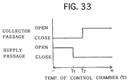
- the heating is carried out too weakly when the temperature of the silicone oil, held in the control chamber CR, is low. Accordingly, as illustrated in Fig. 3, the bimetal spiral spring 18 rotates the rotary valve 19 to the left in the drawing by way of the valve shaft 17. In this instance, the first collector hole 3b and the second collector hole 19a are not communicated with each other, but the first supply hole 3d and the second supply hole 19b are communicated with each other. Hence, as designated at a rotary angle of -A° in Fig. 5, the collector concavity 3a, etc., are closed in the control chamber CR, and simultaneously the supply groove 3c, etc., are opened into the control chamber CR. Note that Fig.
- Figs. 10, 15, 29, 33 and 37 likewise show the operational graph schematically.
- the silicone oil, held in the heat-generating chamber 10 is not supplied into the control chamber CR by way of the collector concavity 3a, the first collector hole 3b and the second collector hole 19a.
- the silicone oil, held in the control chamber CR is supplied into the heat-generating chamber 10 by way of the second supply hole 19b, the first supply hole 3d and the supply groove 3c.
- the silicone oil, held in the control chamber CR, is readily delivered out into the space between the front wall surface of the heat-generating chamber 10 and the front side surface of the rotor 16 by way of the central apertures 16a.
- the silicone oil is supplied into the space between the wall surface of the heat-generating chamber 10 and the outer surface of the rotor 16, the inevitable air is pushed by the silicone oil to move from the upper side of the heat-generating chamber 10 into the control chamber CR by way of the gas groove 3e and the gas hole 3f.
- the bubbles scarcely exist in the space between the wall surface of the heat-generating chamber 10 and the outer surface of the rotor 16.
- the heat generation is increased (i.e., the capacity enlargement) in the space between the wall surface of the heat-generating chamber 10 and the outer surface of the rotor 16, thereby intensifying the heating.
- the heating is carried out too strongly when the temperature of the silicone oil, held in the control chamber CR, is high. Accordingly, as illustrated in Fig. 4, the bimetal spiral spring 18 rotates the rotary valve 19 slightly to the right in the drawing by way of the valve shaft 17. Thus, the first collector hole 3b and the second collector hole 19a are communicated with each other, and simultaneously the first supply hole 3d and the second supply hole 19b are not communicated with each other. Specifically, as designated at a rotary angle of +A° in Fig. 5, the collector concavity 3a, etc., are opened into the control chamber CR, and simultaneously the supply groove 3c, etc., are closed in the control chamber CR.
- the silicone oil, held in the heat-generating chamber 10 is collected into the control chamber CR by way of the collector concavity 3a, the first collector hole 3b and the second collector hole 19a.
- the silicone oil, held between the front wall surface of the heat-generating chamber 10 and the front side surface of the rotor 16 is readily collected into the collector chamber CR by way of the central apertures 16a.
- the silicone oil, collected into the control chamber CR is not supplied into the heat-generating chamber 10 by way of the second supply hole 19b, the first supply hole 3d and the supply groove 3c.
- the silicone oil When the silicone oil is collected into the control chamber CR, the inevitable air is pushed by the silicone oil to move from the upper side of the control chamber CR into the heat-generating chamber 10 by way of the gas groove 3e and the gas hole 3f. Thus, the bubbles exist in the space between the wall surface of the heat-generating chamber 10 and the outer surface of the rotor 16. All in all, the heat generation is decreased (i.e., the capacity reduction) in the space between the wall surface of the heat-generating chamber 10 and the outer surface of the rotor 16, thereby relieving the heating.
- the viscous heater can reliably carry out the capacity reduction and the capacity enlargement by the variation of the physical properties in itself. Therefore, the viscous heater does not necessarily require an electromagnetic clutch when the heating is needed or when the heating is not needed. In addition, the viscous heater does not need an external input for actuating the capacity variation. All in all, the viscous heater can realize the cost reduction and the weight reduction in heating apparatuses.
- the sum of the internal volumes of the enclosed heat-generating chamber 10, collector concavity 3a, etc., supply groove 3c, etc., and control chamber CR is little varied when the silicone oil is collected from the heat-generating chamber 10 into the control chamber CR, or when the silicone oil is supplied from the control chamber CR into the heat-generating chamber 10 reversibly. Accordingly, there hardly arises the negative pressure which results from the transfer of the silicone oil. As a result, the silicone oil is not brought into contact with newly introduced air, and is replenished with water, which is held in the air, at any time. Thus, the silicone oil is not deteriorated, and is not adversely affected by the air or water. Thus, in the viscous heater, the endurable heat generation can be inhibited from degrading even after a long period of service.
- the viscous heater can produce such extra advantages that the number of component pats can be reduced, because the single independent rotary valve 19 is employed and controlled synchronously.
- the viscous heater is good in terms of boardability onto vehicles, or the like, because its axial length is reduced.
- variable capacity type viscous heater of the Second Preferred Embodiment embodies Claims 1 through 5, 11, 16, 20, 21, 24, 27, 28, 32, 34, 35 and 40 through 43.
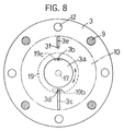
- a second collector hole 19c of a rotary valve 19 is drilled through at a position which is disposed slightly on the right side in the rotary direction with respect to that of the First Preferred Embodiment in the drawing.
- the Second Preferred Embodiment has the same arrangements as those the First Preferred Embodiment. Accordingly, the same arrangements will be described with the same reference numerals.
- the heating is carried out too weakly when the temperature of the silicone oil, held in the control chamber CR, is low. Accordingly, as illustrated in Fig. 7, the rotary valve 19 is rotated to the left in the drawing. In this instance, the first collector hole 3b and the second collector hole 19c are not communicated with each other, but the first supply hole 3d and the second supply hole 19b are communicated with each other. Hence, as designated at a rotary angle of -A° in Fig. 10, the collector concavity 3a, etc., are closed in the control chamber CR, and simultaneously the supply groove 3c, etc., are opened into the control chamber CR.
- the silicone oil, held in the heat-generating chamber 10 is not collected into the control chamber CR, but the silicone oil, held in the control chamber CR, is supplied into the heat-generating chamber 10. All in all, the heat generation is increased (i.e., the capacity enlargement) in the space between the wall surface of the heat-generating chamber 10 and the outer surface of the rotor 16, thereby intensifying the heating.
- the rotary valve 19 is rotated slightly to the right in the drawing when the temperature of the silicone oil, held in the control chamber CR, is increased slightly.
- the first collector hole 3b and the second collector hole 19a are communicated with each other, and the first supply hole 3d and the second supply hole 19b are communicated with each other.
- the collector concavity 3a, etc. are opened in the control chamber CR, and simultaneously the supply groove 3c, etc., are opened into the control chamber CR.
- the silicone oil, held in the heat-generating chamber 10 is collected into the control chamber CR by way of the collector concavity 3a, etc., by the Weissenberg effect, and the silicone oil, held in the control chamber CR, is also supplied into the heat-generating chamber 10 by way of the supply groove 3c, etc.
- the heat generation is increased quickly in the space between the wall surface of the heat-generating chamber 10 and the outer surface of the rotor 16, because the angular momentum of the rotor 16 is increased.
- the angular momentum is required to accelerate the low-speed silicone oil, which is supplied from the supply groove 3c, etc., into the heat-generating chamber 10. Therefore, the viscous heater can intensify the heating in a short period of time.
- the heating is carried out too strongly when the temperature of the silicone oil, held in the control chamber CR, is high. Accordingly, as illustrated in Fig. 9, the rotary valve 19 is rotated to the right in the drawing. In this instance, the first collector hole 3b and the second collector hole 19c are communicated with each other, but the first supply hole 3d and the second supply hole 19b are not communicated with each other. Specifically, as designated at a rotary angle of +B° in Fig. 10, the collector concavity 3a, etc., are opened into the control chamber CR, and the supply groove 3c, etc., are closed in the control chamber CR.
- the silicone oil, held in the heat-generating chamber 10 is collected into the control chamber CR, but the silicone oil, collected in the control chamber 10, is not supplied into the heat-generating-chamber 10.
- the heat generation is decreased (i.e., the capacity reduction) in the space between the wall surface of the heat-generating chamber 10 and the outer surface of the rotor 16, thereby relieving the heating.
- the viscous heater of the Second Preferred Embodiment can operate and produce advantages in the same manner as the First Preferred Embodiment.
- variable capacity type viscous heater of the Third Preferred Embodiment embodies Claims 1 through 7, 11, 16, 20, 21, 24, 27, 28, 32, 34, 35, 40 through 43.
- the viscous heater employs a rear plate 21 which is protruded rearwardly in a central region.
- a collector concavity 21a is dented so that it faces a central region of a heat-generating chamber 10.
- a first collector hole 21b is drilled through at a position on an outer side of the collector concavity 21a so that it extends to a rear-end surface of the rear plate 21.
- a first supply hole 21c is drilled through so that it also extends to a rear-end surface of the rear plate 21.
- a spiral groove 15a is formed on an elongated rear-end peripheral surface of a driving shaft 15, a spiral groove 15a is formed.
- the spiral groove 15a works as the compulsory supply means, and that the portion around the spiral groove 15a of the driving shaft 15 is accommodated in the first collector hole 21b so as to constitute a simple screw-type pump.
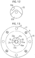
- the viscous heater employs a rotary valve 22 as illustrated in Fig. 12.
- a sector-shaped collector groove 22a is dented so that it can communicate with the first collector 21b according to a rotary angle of the rotary valve 22
- a sector-shaped second supply groove 22b is dented so that it can communicate with the first supply hole 21c regardless of a rotary angle of the rotary valve 22.
- the collector concavity 21a, the first collector hole 21b and the second collector groove 22a constitute the collector passage.
- the first supply hole 21c and the second supply groove 22b constitute the supply passage.
- the Third Preferred Embodiment has the same arrangements as those the First Preferred Embodiment. Accordingly, the same arrangements will be described with the same reference numerals.
- the heating is carried out too weakly when the temperature of the silicone oil, held in the control chamber CR, is low. Accordingly, as illustrated in Fig. 13, the rotary valve 22 is rotated to the left in the drawing. In this instance, the first collector hole 21b and the second collector groove 22a are not communicated with each other. Hence, as designated at a rotary angle of -A° in Fig. 15, the collector concavity 21a, etc., are closed in the control chamber CR, and the first supply hole 21c, etc., are opened into the control chamber CR.
- the silicone oil, held in the heat-generating chamber 10 is not supplied into the control chamber CR by way of the collector concavity 21a, the first collector hole 21b and the second collector hole 22a.
- the spiral groove 15a forcibly supplies the silicone oil, collected in the control chamber CR, into the heat-generating chamber 10 by way of the first supply hole 21c when the driving shaft 15 is rotated. All in all, the heat generation is increased (i.e., the capacity enlargement) in the space between the wall surface of the heat-generating chamber 10 and the outer surface of the rotor 16, thereby intensifying the heating in a short period of time.
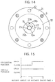
- the heating is about to be carried out too strongly when the temperature of the silicone oil, held in the control chamber CR, is increased. Accordingly, as illustrated in Fig. 14, the rotary valve 22 is rotated to the right in the drawing. Thus, the first collector hole 21b and the second collector groove 22a are communicated with each other. Specifically, as designated at a rotary angle of +A° in Fig. 15, the collector concavity 21a, etc., are opened into the control chamber CR.
- the spiral groove 15a forcibly supplies the silicone oil, collected in the control chamber CR, into the heat-generating chamber 10
- the silicone oil, held in the heat-generating chamber 10 is collected into the control chamber CR by way of the collector concavity 21a, the first collector hole 21b and the second collector groove 22a.
- the heat generation is decreased (i.e., the capacity reduction) in the space between the wall surface of the heat-generating chamber 10 and the outer surface of the rotor 16, thereby relieving the heating.
- the viscous heater of the Third Preferred Embodiment can operate and produce advantages in the same manner as the First Preferred Embodiment.
- variable capacity type viscous heater of the Fourth Preferred Embodiment embodies Claims 1 through 5, 8 through 13, 15, 16, 20, 21, 24, 27, 28, 34, 35 and 40 through 43.
- the viscous heater employs a rear plate 30 as illustrated in Fig. 16.
- a gas passage is formed in the rear plate 30, and a gas hole 30b.
- the gas groove 30a is dented in the rear plate 30, and is extended from a top end of a heat-generating chamber 10 to an inner side.
- the gas hole 30b is communicated with an inner end of the gas groove 30a, and is drilled through up to an upper end of a control chamber CR.
- the gas groove 30a is chamfered around the opening thereof on the side of the heat-generating chamber 10 (not shown in the drawing).
- a first collector hole 30c is drilled through at an upper position in a central region of the rear plate 30.
- the first collector hole 30c works as the collector passage. As illustrated in Figs. 17 (A) and (B), the opening of the first collector hole 30c is formed like an arc on the side of the heat-generating chamber 10.
- the opening of the first collector hole 30c includes an arc-shaped portion which is formed about the center S1 on an opposite rim on a rear side with respect to a rotary direction of a rotor 16 shown by an alternate-long-and-two-dash line of Fig. 17 (A), and a linear portion which is on another opposite rim on a front side with respect to the rotary direction of the rotor 16. Furthermore, the first collector hole 30c is subjected to chamfering 30d around the opening on a side of the heat-generating chamber 10.
- a first supply hole 30e is also drilled through up to a rear end surface of the rear plate 30.
- the first supply hole 30e has a larger communicating area than that of the first supply hole 30c, and works as part of the supply passage.
- a supply groove 30f is dented in the rear plate 30.
- the supply groove 30f is opened on a side of the heat-generating chamber 10, and is communicated with the first supply hole 30e at an inner end.
- the supply groove 30f constitutes the rest of the supply passage.
- the supply groove 30f works as the distributor passage.
- the supply groove 30f is extended to an outer periphery of the rotor 16, and is inclined with respect to a diametric direction of the rotor 16 on a forward side with respect to the rotary direction of the rotor 16 shown by an alternate-long-and-two-dash line of Fig. 16. As illustrated in Fig. 18, the supply groove 30f is subjected to chamfering 30g around the opening on a side of the heat-generating chamber 10.
- the Fourth Preferred Embodiment has the same arrangements as those the First Preferred Embodiment. Accordingly, the same arrangements will be described with the same reference numerals.
- the rotor 16 rotates in the heat-generating chamber 10, thereby supplying the silicone oil, held in the control chamber CR, into the heat-generating chamber 10 by way of the supply groove 30f and the first supply hole 30e by the own weight of the silicone oil and the extendible viscosity thereof.
- the silicone oil, collected in the control chamber CR is supplied to an outer peripheral region of the heat-generating chamber 10 by way of the supply groove 30f smoothly and quickly.
- the silicone oil, supplied to the outer peripheral region of the heat-generating chamber 10 is developed by the Weissenberg effect up to the central region of the heat-generating chamber 10 over the entire region quickly.
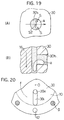
- a viscous heater is prepared as illustrated in Figs. 19 and 20. Note that the comparative viscous heater embodies Claims 1 through 5, 11, 16, 20, 21, 24, 27, 28, 34, 35 and 40 through 43, but does not embody Claims 8 through 10, 12 and 13.
- a first collector hole 30h is drilled through in a rear plate 30.
- the first collector hole 30h is formed as a circular configuration, which has the center at S2, in cross-section. Note that the first collector hole 30h is not chamfered around the opening on a side of a heat-generating chamber 10. Further, as illustrated in Fig. 20, a supply groove 30i is dented in the rear plate 30.
- the supply groove 30i is extended to a outer periphery of a rotor 16, but is not inclined with respect to a diametric direction of the rotor 16 on a forward side with respect to the rotary direction of the rotor 16 shown by a alternate-long-and-two-dash line of Fig. 20. Note that the supply groove 30i is not chamfered around the opening on a side of the heat-generating chamber 10. Unless otherwise specified, the comparative viscous heater has the same arrangements as those the Fourth Preferred Embodiment.
- the silicone oil, collected in the control chamber CR is extremely less likely to be supplied to an outer peripheral region of the heat-generating chamber 10.
- the disadvantage is believed to be caused by the following arrangement: the supply groove 30i is extended to an outer periphery of the rotor 16 without inclination as illustrated in Fig. 20.
- the silicone oil, held in the supply groove 30i is pressed onto a lateral-wall side of the supply groove 30i by the rotation of the rotor 16.
- the silicone oil is believed to be less likely to move to an outer peripheral side of the rotor 16.
- the silicone oil is less likely to move into the heat-generating chamber 10, because the opening of the supply groove 30i is formed substantially perpendicularly on the side of the heat-generating chamber 10.
- the first collector hole 30c is formed as a configuration which is less likely to exert the large contraction force "s" to the bubbles "a".
- the bubbles "a” are likely to move into the control chamber CR smoothly and quickly, because the opening of the first collector hole 30c is subjected to the chamfering 30e on the side of the heat-generating chamber 10.
- the supply groove 30f is extended to an outer periphery of the rotor 16 while it is inclined with respect to a diametric direction of the rotor 16 on a forward side with respect to the rotary direction of the rotor 16.
- the supply groove 30f is provided with the chamfering 30g.
- a first collector hole 30j is drilled through in a rear plate 30.
- the first collector hole 30j is formed as an arc which is formed about the center S1.
- the first collector hole 30j is formed as an arc which is formed about the center S3.
- the center S3 is disposed on a rear side with respect to the center S1 in the rotary direction of the rotor 16, and that the radius of the arc, which is disposed on an opposite rim and formed about the center S3, is larger than that of the arc, which is disposed on an opposite rim and formed about the center S1.
- the viscous heater of the Fifth Preferred Embodiment has the same arrangements as those the Fourth Preferred Embodiment.
- the first collector hole 30j has a configuration which little exerts a large contraction force "s" to bubbles "a". Hence, the viscous heater can operate and produce advantages in the same manner as the Fourth Preferred Embodiment.
- a first collector hole 30k is drilled through in a rear plate 30.
- the first collector hole 30k is formed as an arc which is formed about the center S1.
- the first collector hole 30k is formed as an arc which is formed about the center S4.
- the center S4 is disposed on a front side with respect to the center S1 in the rotary direction of the rotor 16, and that the radius of the arc, which is disposed on another opposite rim and formed about the center S4, is larger than that of the arc, which is disposed on an opposite rim and formed about the center S1.
- the viscous heater of the Sixth Preferred Embodiment has the same arrangements as those the Fourth Preferred Embodiment.
- the first collector hole 30k has a configuration which can exert an expansion force "b" to bubbles "a". Hence, the viscous heater can operate and produce advantages in the same manner as the Fourth Preferred Embodiment.
- variable capacity type viscous heater of the Seventh Preferred Embodiment embodies Claims 1 through 5, 8 through 12, 14 through 16, 20, 21, 24, 27, 28, 34, 35 and 40 through 43.
- a supply groove 30l is dented in a rear plate 30.
- the supply groove 30l is extended to an outer periphery of a rotor 16, and is curved with respect to a diametric direction of the rotor 16 on a forward side with respect to a rotary direction of the rotor 16 shown by an alternate-long-and-two-dash line of the drawing.
- the supply groove 30l is subjected to chamfering 30m around the opening on a side of a heat-generating chamber 10, but only on a front-side opposite rim with respect to the rotary direction of the rotor 16.
- the viscous heater of the Seventh Preferred Embodiment has the same arrangements as those the Fourth Preferred Embodiment.
- the silicone oil held in the supply groove 30l, is likely to be moved by the rotation of the rotor 16 to an outer peripheral side of the rotor 16.
- the viscous heater can operate and produce advantages in the same manner as the Fourth Preferred Embodiment.
- variable capacity type viscous heater of the Eighth Preferred Embodiment embodies Claims 1 through 4, 11 through 14, 16, 20, 21, 24, 27, 28 and 32 through 43.
- the viscous heater employs a rear plate 31 and a rotary valve 32 as illustrated in Fig. 24.
- a gas passage is formed in the rear plate 31.
- the gas passage includes a gas groove 31a, and a first gas hole 31b.
- the gas groove 31a is dented in the rear plate 30, and is extended from a top end of a heat-generating chamber 10 to an inner side.
- the gas hole 31b is communicated with an inner end of the gas groove 31a, and is drilled through up to an upper end of a control chamber CR.
- a first collector hole 31c is drilled through up to a rear-end surface of the rear plate 31.
- the first collector hole 31c is disposed at an upper position obliquely with respect to a central region of the rear plate 31, and is formed as a circular shape in cross-section. Note that the first collector hole 31c works as the collector passage. Furthermore, in the rear plate 31, a first supply hole 31d is also drilled through up to a rear-end surface of the rear plate 30 at a lower position in a central region of the rear plate 30. The first supply hole 31d has an identical diameter with that of the first collector hole 31c. Note that the first supply hole 31d works as part of the supply passage. Moreover, a supply groove 31e is dented in the rear plate 30.
- the supply groove 31e is opened on a side of the heat-generating chamber 10, and is communicated with the first supply hole 31d at an inner end, thereby constituting the rest of the supply passage. Note that the supply groove 31e works as the distributor passage. As illustrated in Figs. 26 through 28, the supply groove 31e is extended to an outer periphery of the rotor 16, and is inclined with respect to a diametric direction of the rotor 16 on a forward side with respect to the rotary direction of the rotor 16.
- the rotary valve 32 has a larger diameter than that of the First through Seventh Preferred Embodiments.
- a single arc-shaped collector-and-supply slot 32a is drilled through.
- the collector-and-supply slot 32a can be communicated with the first collector hole 31c and the first supply hole 31d.
- an arc-shaped second gas slot 32b is drilled through.
- the second gas slot 32b can be communicated with the first gas hole 31b.
- the Eighth Preferred Embodiment has the same arrangements as those the First Preferred Embodiment. Accordingly, the same arrangements will be described with the same reference numerals.
- the heating is carried out too weakly when the temperature of the silicone oil, held in the control chamber CR, is low. Accordingly, as illustrated in Fig. 26, the rotary valve 32 is rotated to the left in the drawing. In this instance, the first collector hole 31c and the collector-and-supply slot 32a are not communicated with each other, but the first supply hole 31d and the collector-and-supply slot 32a are communicated with each other. Hence, as designated at a rotary angle of -A° in Fig. 29, the first collector hole 31c, etc., are closed in the control chamber CR, the first supply hole 31d, etc., are opened into the control chamber CR, and the gas groove 31a, etc., are further opened into the control chamber CR.
- the gas groove 31a, etc. are opened by the rotary valve 32 so that the gas, held in the heat-generating chamber 10, is moved into the control chamber CR by way of the gas groove 31a, etc., in the capacity enlargement.
- the silicone oil, held in the heat-generating chamber 10 is likely to be supplied into the heat-generating chamber 10. All in all, the heating can be securely intensified.
- the rotary valve 32 is rotated slightly to the right in the drawing when the temperature of the silicone oil, held in the control chamber CR, is increased slightly.
- the collector hole 31c and the first supply hole 31d are communicated with the collector-and-supply slot 32a, and simultaneously the first gas hole 31b and the second gas hole 32b are communicated with each other.
- the collector hole 31c, etc. are opened in the control chamber CR
- the first supply hole 31d, etc. are opened into the control chamber CR
- the gas groove 31a, etc. are opened into the control chamber CR.
- the rotary valve 32 opens the gas groove 31a, etc., so that the flow of the silicone oil can be facilitated.
- the rotary valve 32 is rotated slightly to the right in the drawing as illustrated in Fig. 28.
- the first collector hole 31c and the collector-and-supply slot 32a are communicated with each other, but the first supply hole 31d and the collector-and-supply slot 32a are not communicated with each other.
- the first gas hole 31b and the second gas hole 32b are not communicated with each other.
- the collector hole 31c, etc. are opened into the control chamber CR.
- the first supply hole 31d, etc. are closed in the control chamber CR, and the gas groove 31a, etc., are closed in the control chamber CR.
- the rotary valve 32 closes the gas passage 31a, etc., so that the gas can be inhibited from moving into the control chamber CR in the capacity reduction.
- the silicone oil can be collected facilitatively as the pressure increases in the heat-generating chamber 10. All in all, the heating can be securely relieved.
- the rotary valve 32 can be simplified, because the collector hole 31c and the first supply hole 31d are opened and closed by the single collector-and-supply slot 32a which is drilled through in the rotary valve 32. Hence, the arrangement is advantageous in terms of costs.
- the viscous heater of the Eighth Preferred Embodiment can operate and produce advantages in the same manner as the First Preferred Embodiment.
- variable capacity type viscous heater of the Ninth Preferred Embodiment embodies Claims 1 through 4, 11 through 14, 16 through 18, 24 through 26, 32, 42 and 43.
- the viscous heater employs a rear plate 33, a reed type flap valve 34, and a bimetal type flap valve 35.
- a first collector hole 31c, etc. are used both as the collector passage and the gas passage.
- the reed type flap valve 34 closes the first collector hole 31c on a side of a control chamber CR.
- the bimetal type flap valve 35 closes a first supply hole 31d on a side of the control chamber CR.
- the viscous heater employs a rear housing body 36 which is free from the second rib protruding into the control chamber CR.
- the Ninth Preferred Embodiment has the same arrangements as those of the First and Eighth Preferred Embodiments. Accordingly, the same arrangements will be described with the same reference numerals.
- the reed type flap valve 34 opens the first collector hole 31c according to the pressure increment in the heat-generating chamber 10, thereby carrying out the capacity reduction.
- the pressure increment results from the heat generated by the silicone oil.
- the bimetal type flap valve 35 opens the first supply hole 31d according to the temperature decrement of the silicone oil, thereby carrying out the capacity enlargement.
- the viscous heater of the Ninth Preferred Embodiment can operate ad produce advantages in the same manner as the First Preferred Embodiment.
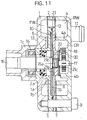
- variable capacity type viscous heater of the Tenth Preferred Embodiment employs a cylinder-shaped rotor 57.
- a substantially cylinder-shaped cylinder block 42 is press-fitted into a cylinder-shaped central housing 41.
- a front housing 45 is bonded by way of a gasket 43.
- a rear plate 46 is bonded by way of a gasket 44.
- the rear plate 46 is further bonded to a rear housing 48 by way of a gasket 47.
- a heat-generating chamber 49 is formed in the cylinder block 42.
- a rib 42a is protruded in a spiral manner.
- the rib 42a is brought into contact with an inner peripheral surface of the central housing 41 so that it forms a spiral-shaped water jacket WJ.
- the water jacket WJ works as the radiator chamber.
- a water inlet port 50 is protruded at a front end, and a water outlet port 51 is protruded at a rear end.
- the water inlet port 50 and the water outlet port 51 are disposed within an identical outer peripheral surface of the central housing 41.
- the water inlet port 50 takes in circulating water, working as the circulating fluid, from an external heating circuit (not shown).
- the water outlet port 51 delivers the circulating water out to the heating circuit.
- the water inlet port 50 and the water outlet port 51 are communicated with the water jacket WJ.
- a pulley 63 is installed to the front housing 45 by way of a bearing apparatus 62.
- the pulley 63 is fastened to a driving shaft 56 by a bolt 64.
- the driving shaft 56 is held rotatably in the front housing 45 and the rear plate 46 by way of shaft-sealing apparatuses 52, 53 and bearing apparatuses 54, 55.
- the driving shaft 56 is further press-fitted into a rotor 57 which has a cylinder-shaped outer peripheral surface. The rotor 57 can thus rotate in the heat-generating chamber 49.
- a collector groove 46a and a supply groove 46b are formed so as to extend to an outer peripheral region of the heat-generating chamber 49.
- the supply groove 46b works as the distributor passage.
- a first supply hole 46c is drilled through to a rear-end surface of the rear plate 48.
- a first supply hole 46d is drilled through to a rear-end surface of the rear plate 48.
- a control chamber CR is formed so that it can be communicated with the first collector hole 46c and the first supply hole 46d.
- a rib 48a is protruded as a ring-like shape.
- a rotary valve 61 is disposed in the rib 48a.
- the rotary valve 61 is engaged with a bimetal spiral spring 58, and is pressed by a coned disk spring 59.
- the rotary valve 61 is further installed to a valve shaft 60 so that it can be rotated by the valve shaft 60.
- a second collector hole and a second supply hole are drilled through.
- the heat is generated almost on a side of the outer peripheral surface of the rotor 57.
- the silicone oil is collected from a outer-peripheral side of the heat-generating chamber 49, and is supplied to an outer-peripheral side of the heat-generating chamber 49.
- the viscous heater of the Tenth Preferred Embodiment can operate and produce advantages in the same manner as the First Preferred Embodiment, etc.
- the variable capacity type viscous heater of the Eleventh Preferred Embodiment opens and closes a first collector hole and a first supply hole by a bimetal type flap valve. For instance, as illustrated in Fig. 33, when a temperature of the silicone oil, held in the control chamber CR, is -T 1 °C, the first collector hole, etc., are closed in the control chamber CR, and the first supply hole, etc., are opened into the control chamber CR. Moreover, when a temperature of the silicone oil, held in the control chamber CR, is in a range of from T 1 to T 2 °C, the first collector hole, etc., are kept being closed in the control chamber CR, and the first supply hole, etc., are closed in the control chamber CR.
- the first collector hole, etc. are opened into the control chamber CR, and the first supply hole, etc., are kept being closed in the control chamber CR.
- the viscous heater of the Eleventh Preferred Embodiment can operate and produce advantages in the same manner as the First Preferred Embodiment.
- variable capacity type viscous heater of the Twelfth Preferred Embodiment embodies Claims 1 through 5, 11 through 13, 15, 16, 20, 22 through 24, 29, 30, 32, 42 and 43.
- a front plate 72 and a rear plate 73 are superimposed by way of an O-ring 75 disposed therebetween, and are accommodated in a front housing body 71.
- the front housing body 71 is fastened to a rear housing body 74 by a plurality of through bolts 77 so that it is closed by the rear housing body 74 with an O-ring 76 disposed therebetween.
- a concavity is dented so that it forms a heat-generating chamber 78 together with a flat front-end surface of the rear plate 73.
- a collector hole 73a is drilled through to a rear-end surface thereof so that it is communicated with a upper central region of the heat-generating chamber 78.
- the collector hole 73a works as the collector passage.
- a supply hole 73b is also drilled through to a rear-end surface thereof, and is disposed on an outside below the collector hole 73a.
- the supply hole 73b works as the supply passage.
- a supply groove 73c is further extended from the supply hole 73b to a lower-side outer region of the heat-generating chamber 78. Note that the supply groove 73c works as the distributor passage.
- arc-shaped fins 72a are protruded forwardly.
- the front plate 72 thus forms a front water jacket FW together with an outer-peripheral-side inner surface of the front housing body 71.
- the front water jacket FW works as the front radiator chamber which neighbors in front of the heat-generating chamber 78.
- arc-shaped fins 73d are protruded rearwardly.
- the rear plate 73 thus forms a rear water jacket RW together with an outer-peripheral-side inner surface of the rear housing body 74.
- the rear water jacket FW works as the rear radiator chamber which neighbors in rear of the heat-generating chamber 78.
- an inner peripheral side of the rear surface of the rear plate 73 and an inner peripheral side of the inner surface of the rear housing body 74 form a control chamber CR which can be communicated with the collector hole 73a and the supply hole 73b.
- a water inlet port (not shown) and a water outlet port (not shown) are formed next to each other.
- the water inlet port and the water outlet port are communicated with the front water jacket FW and the rear water jacket RW.
- a shaft-sealing apparatus 79 is disposed next to the heat-generating chamber 78.
- bearing apparatuses 80, 81 are disposed.
- a driving shaft 82 is held rotatably in the front housing body 71 and the front plate 72 by way of the shaft-sealing apparatus 79 and the bearing apparatuses 80, 81.
- a flat plate-shaped rotor 83 is press-fitted so that it can rotate in the heat-generating chamber 78.
- a plurality of central apertures 83a are drilled through so that they are communicated with the heat-generating chamber 78 longitudinally.
- a plurality of through holes 83b are drilled through so as to enhance the effect of shearing a silicone oil later described.
- the silicone oil is interposed in the space between the wall surface of the heat-generating chamber 78 and the outer surface of the rotor 83, and in the control chamber CR. Note that the silicone oil works as the viscous fluid.
- a fixture ring 84 is fixed at a rear end of the driving shaft 82 in the control chamber CR. Further, the fixture ring 84 is fastened to guide pins 85a, 85b which can extend in a diametric direction. Furthermore, arc-shaped adjusting valves 86a, 86b are assembled with the guide pins 85a, 85b in a manner being movable in a diametric direction but being inhibited from rotating, because the guide pins 85a, 85b are formed as a square shape in cross-section.
- the adjusting valves 86a, 86b are always urged by compression springs 87a, 87b which are disposed on a head side of the guide pins 85a, 85b.
- the Twelfth Preferred Embodiment has the same arrangements as those the First Preferred Embodiment, etc.
- a revolving speed of the driving shaft 82 is high: namely; when it is designated at a revolving speed of +R in Fig. 37, the adjusting valves 86a, 86b are subjected to a large centrifugal force so that they are separated away from a side of the driving shaft 82 as illustrated in Fig. 36. Accordingly, an opening degree of the collector hole 73a is large on a side of the control chamber CR, but an opening degree of the supply hole 73b is small on a side of the control chamber CR. Consequently, the supply of the silicone oil into the heat-generating chamber 78 terminates virtually, but the collection of the silicone oil into the control chamber CR continues virtually.
- the silicone oil, held in the heat-generating chamber 78, is inhibited from elevating the temperature, and is eventually inhibited from deteriorating.
- the heat generation can be maintained even after the viscous heater is operated for a long period of time.
- the variable capacity type viscous heater of the Thirteenth Preferred Embodiment employs arc-shaped adjusting valves 90a, 90b.
- a fixture ring 91 is fixed to a rear end of a driving shaft 82 by a bolt 93 by way of a washer 94 in a control chamber CR.
- the adjusting valves 90a, 90b are then disposed under the fixture ring 91 swingably by swinging pins 92a, 92b which extend in an axial direction.
- Figs. 38 a fixture ring 91 is fixed to a rear end of a driving shaft 82 by a bolt 93 by way of a washer 94 in a control chamber CR.
- the adjusting valves 90a, 90b are then disposed under the fixture ring 91 swingably by swinging pins 92a, 92b which extend in an axial direction.
- the adjusting valves 90a, 90b are provided with torsional coil springs 95a, 95b which are disposed between the driving shaft 82 and stoppers formed on the adjusting valves 90a, 90b.
- the torsional coil springs 95a, 95b always urge the adjusting valves 90a, 90b toward the driving shaft 82.
- the Thirteenth Preferred Embodiment has the same arrangements as those of the Twelfth Preferred Embodiment.
- the viscous heater of the Thirteenth Preferred Embodiment can operate and produce advantages in the same manner as the Twelfth Preferred Embodiment.
- the collector hole 73a and the supply hole 73b are not opened or closed completely by the above-described adjusting valves 86a, 86b or by the adjusting valves 90a, 90b.
- the collector hole 73a and the supply hole 73b are opened or closed intermittently in accordance with an opening or closing angle with respect to one revolution of the driving shaft 82, for instance, in accordance with the extent of the opening degree as set forth in the Twelfth or Thirteenth Preferred Embodiment.
- variable capacity type viscous heater of the Fourteenth Preferred Embodiment embodies Claims 1 through 5, 24, 31, 32, 42 and 43.
- a front plate 102 and a rear plate 103 are superimposed by way of an O-ring 105 disposed therebetween, and are accommodated in a front housing body 101.
- the front housing body 101 is fastened to a rear housing body 104 by a plurality of through bolts 107 so that it is closed by the rear housing body 104 with an O-ring 106 disposed therebetween.
- a concavity is dented so that it forms a heat-generating chamber 108 together with a flat front-end surface of the rear plate 103.
- a collector hole 103a and a supply hole 103b are drilled through to a rear-end surface thereof.
- the collector hole 103a is communicated with an upper central region of the heat-generating chamber 108.
- the supply hole 103b is communicated with a lower central region of the heat-generating chamber 108. Note that the supply hole 103b is tapered from narrow to wide toward a side of a control chamber CR so that a seating surface is formed.
- a plurality of arc-shaped fins 102a are protruded forwardly.
- the front plate 102 thus forms a front water jacket FW together with an outer-peripheral-side inner surface of the front housing body 101.
- the front water jacket FW works as the front radiator chamber which neighbors in front of the heat-generating chamber 108.
- a plurality of arc-shaped fins 103e are protruded rearwardly.
- the rear plate 103 thus forms a rear water jacket RW together with an outer-peripheral-side inner surface of the rear housing body 104.
- the rear water jacket FW works as the rear radiator chamber which neighbors in rear of the heat-generating chamber 108.
- an inner peripheral side of the rear surface of the rear plate 103 and an inner peripheral side of the inner surface of the rear housing body 104 form a control chamber CR which is communicated with the collector hole 103a and the supply hole 103b.
- a water inlet port (not shown) and a water outlet port (not shown) are formed next to each other. The water inlet port and the water outlet port are communicated with the front water jacket FW and the rear water jacket RW.
- the front plate 102 is provided with a boss 102b.
- a bearing apparatus 109 is disposed which includes a built-in shaft-sealing apparatus.
- the front housing body 101 is provided with a boss 101b.
- a bearing apparatus 110 is disposed. Accordingly, a driving shaft 112 is held rotatably by these bearing apparatuses 109, 110.
- An electromagnetic clutch MC is further disposed in the boss 101b of the front housing body 101. In the electromagnetic clutch MC, a pulley 122 is held rotatably to the boss 101b by way of a bearing apparatus 121, and an exciting coil 123 is disposed so as to be positioned in the pulley 122.
- a hub 126 is fixed to the driving shaft 112 by screwing a bolt 124 into the driving shalt 112 and press-fitting a key 125 thereinto.
- the hub 125 is further fixed to an armature 129 by way of a rubber member 127 and a flange 128.
- the pulley 122 is rotated by an engine (not shown) of vehicles by way of a belt.
- a flat plate-shaped rotor 113 is press-fitted so that it can rotate in the heat-generating chamber 108.
- a plurality of central apertures 113a are drilled through so that they are communicated with the heat-generating chamber 108 longitudinally.
- a silicone oil is interposed in the space between the wall surface of the heat-generating chamber 108 and the outer surface of the rotor 113, and in the control chamber CR. Note that the silicone oil works as the viscous fluid.
- the rear housing body 104 is provided with a swollen portion which is protruded into the control chamber CR.
- a spool chamber 104a is formed in the swollen portion.
- the spool chamber 104a is closed by a lid member 130.
- the spool chamber 104a thus closed by the lid member 130 can extend longitudinally.
- a spool 132 is disposed in the spool chamber 104a.
- a compression spring 131 is further interposed between the spool 132 and an opposite end surface of the spool chamber 104a on a side of the heat-generating chamber 108.
- the spool 132 thus interposed by the compression spring 131 is accommodated in the spool chamber 104a slidably in longitudinal directions.
- the spool chamber 104a is communicated with the atmosphere on one of the opposite ends on a side of the heat-generating chamber 108 by an atmosphere hole 104b which penetrates through the swollen member.
- the spool chamber 104 is further communicated with the control chamber CR on another one of the opposite ends by a control hole 104c which penetrates through the swollen member.
- a sphere 134 is fixed so that it can open and close the supply hole 103b.
- the spool 132, etc. thus constitute the spool valve.
- the Fourteenth Preferred Embodiment has the same arrangements as those the First Preferred Embodiment, etc.
- the viscous heater when a revolving speed of the driving shaft 112 is so low that the heat generation is small, the gaseous pressure is relatively low in the control chamber CR, and the silicone oil is contracted. Accordingly, the pressure, which is introduced into the spool chamber 104a from the control chamber CR by way of the control hole 104c, yields to the summed force, which results from the urging force of the compression spring 131 and the atmospheric pressure introduced through the atmosphere hole 104b. Consequently, the spool 132 retracts so as to get way from the heat-generating chamber 108.
- an opening degree of the supply hole 103b is enlarged on a side of the control chamber CR by the sphere 134 by way of the rod 133, and the supply of the silicone oil, held in the control chamber CR, is started, or the supplying amount is increased. All in all, the heat generation is increased in the space between the wall surface of the heat-generating chamber 108 and the outer surface of the rotor 113 (i.e., capacity enlargement), and thereby the heating is intensified.
- an opening degree of the supply hole 103b is reduced on a side of the control chamber CR by the sphere 134 by way of the rod 133, and the supply of the silicone oil, held in the control chamber CR, is terminated, or the supplying amount is decreased. All in all, the silicone oil, held in the heat-generating chamber 108, is inhibited from elevating the temperature, and is eventually inhibited from deteriorating. In addition, the heat generation can be maintained even after the viscous heater is operated for a long period of time. Unless otherwise specified, the viscous heater of the Fourteenth Preferred Embodiment can operate and produce advantages in the same manner as the First Preferred Embodiment, etc.
- the viscous heater of the Fourteenth Preferred Embodiment in operation, is in a stationary state where the collected amount of the silicone oil, collected by way of the collector hole 103a, is equal to the supply amount of the silicone oil, supplied by way of the supply hole 103b.
- a storage amount of the silicone oil in initial operation is equal to a storage amount thereof in operation, the mechanics in the control chamber CR can be investigated ad determined schematically as hereinafter designated.
- P designates a pressure
- V designates a volume
- T designates an absolute temperature
- M designates a mass
- ⁇ designates a solubility of air into the silicone oil
- ⁇ designates a density of the silicone oil
- ⁇ designates a thermal expansion coefficient of the silicone oil.
- i designates the initial operation
- k designates the operation
- a designates "in air”
- o designates "in the silicone oil”.
- T i in the air is equal to T i in the silicone oil.
- V ak V ai - V oi ⁇ (T k - T i ) + ⁇ M o / ⁇ ak .
- Fig. 43 (B) the mechanics in the spool chamber 104 can be investigated and determined schematically as hereinafter designated. In this investigation, the symbols and subscripts, which are the same as above, are used.
- A designates a cross-sectional area of the spool 132
- K designates a spring constant of the compression coil spring 131
- x designates a displacement of the spool 132 from 0 at which the spool 132 is not subjected to the urging force of the compression spring 131.
- variable capacity type viscous heater of the Fourteenth Preferred Embodiment are all in all, it is apparent that, when manufacturing the variable capacity type viscous heater of the Fourteenth Preferred Embodiment, these relationships can be taken into account.
- a shape memory alloy, a thermoactuator, or the like can be employed as the actuating means for the first and second valve means.
- the actuating means itself can work as the valve means.
- the heating can be carried out optimally in accordance with external environments, such as a water temperature in a radiator, a revolving speed of the engine or the viscous heater, and a passenger compartment, when the following arrangement is employed: namely; the rotary valve can be connected to a motor, and the motor can be controlled by an external input so as to open and close the supply passage; or an electromagnetic valve can be employed as the first valve means, the second valve means and/or the third valve means, and the electromagnetic valve can be controlled by an external input so as to open and close the collector passage and/or the supply passage.
- external environments such as a water temperature in a radiator, a revolving speed of the engine or the viscous heater, and a passenger compartment
- the first valve means, the second valve means and/or the third valve means are controlled independently, it is possible to finely carry out the temperature control, because the collector passage, the supply passage and/or the gas passage can be opened and closed by, for instance, independent external inputs.
- variable capacity type viscous heater set forth in Claim 6 or 7 can employ an off-set type screw pump whose driving shaft is off-set to the driving shaft of the viscous heater as the compulsory supplying means.
- the viscous heater can employ a gear pump, a trochoid pump, a centrifugal pump, or the like. When the driving shaft of these pumps are off-set to the driving shaft of the viscous heater, the pumps can be provided with another driving source.
Landscapes
- Engineering & Computer Science (AREA)
- Chemical & Material Sciences (AREA)
- Combustion & Propulsion (AREA)
- Physics & Mathematics (AREA)
- Thermal Sciences (AREA)
- Mechanical Engineering (AREA)
- General Engineering & Computer Science (AREA)
- Air-Conditioning For Vehicles (AREA)
- Electrical Discharge Machining, Electrochemical Machining, And Combined Machining (AREA)
Applications Claiming Priority (10)
| Application Number | Priority Date | Filing Date | Title |
|---|---|---|---|
| JP285266/95 | 1995-11-01 | ||
| JP28526695 | 1995-11-01 | ||
| JP28526695 | 1995-11-01 | ||
| JP17815396 | 1996-07-08 | ||
| JP17815396 | 1996-07-08 | ||
| JP178153/96 | 1996-07-08 | ||
| JP229058/96 | 1996-08-29 | ||
| JP22905896 | 1996-08-29 | ||
| JP22905896 | 1996-08-29 | ||
| PCT/JP1996/003207 WO1997016323A1 (fr) | 1995-11-01 | 1996-10-31 | Rechauffeur a liquide visqueux a capacite variable |
Publications (3)
| Publication Number | Publication Date |
|---|---|
| EP0800942A1 true EP0800942A1 (fr) | 1997-10-15 |
| EP0800942A4 EP0800942A4 (fr) | 1998-05-20 |
| EP0800942B1 EP0800942B1 (fr) | 2002-03-27 |
Family
ID=27324531
Family Applications (1)
| Application Number | Title | Priority Date | Filing Date |
|---|---|---|---|
| EP96935522A Expired - Lifetime EP0800942B1 (fr) | 1995-11-01 | 1996-10-31 | Rechauffeur a liquide visqueux a capacite variable |
Country Status (6)
| Country | Link |
|---|---|
| US (1) | US5845608A (fr) |
| EP (1) | EP0800942B1 (fr) |
| KR (1) | KR100241410B1 (fr) |
| CA (1) | CA2209118C (fr) |
| DE (1) | DE69620146T2 (fr) |
| WO (1) | WO1997016323A1 (fr) |
Cited By (6)
| Publication number | Priority date | Publication date | Assignee | Title |
|---|---|---|---|---|
| EP0844445A1 (fr) * | 1996-11-20 | 1998-05-27 | Denso Corporation | Générateur de chaleur à fluide visqueux |
| EP0841203A3 (fr) * | 1996-11-11 | 1999-01-13 | Kabushiki Kaisha Toyoda Jidoshokki Seisakusho | Dispositif de chauffage pour véhicules. |
| EP0862028A3 (fr) * | 1997-02-26 | 1999-01-13 | Kabushiki Kaisha Toyoda Jidoshokki Seisakusho | Générateur de chaleur à fluide visqueux |
| EP0862029A3 (fr) * | 1997-02-28 | 1999-01-13 | Kabushiki Kaisha Toyoda Jidoshokki Seisakusho | Générateur de chaleur à friction pour véhicules |
| EP0773122A3 (fr) * | 1995-11-13 | 1999-01-20 | Kabushiki Kaisha Toyoda Jidoshokki Seisakusho | Système de chauffage pour automobile |
| CN1105656C (zh) * | 1997-11-28 | 2003-04-16 | 本田技研工业株式会社 | 用于混合型车辆的控制系统 |
Families Citing this family (6)
| Publication number | Priority date | Publication date | Assignee | Title |
|---|---|---|---|---|
| RU2410247C2 (ru) | 2004-02-26 | 2011-01-27 | Вентек, Ллк | Вспомогательная нагревательная система транспортного средства |
| US7669244B2 (en) * | 2004-10-21 | 2010-02-23 | Cisco Technology, Inc. | Method and system for generating user group permission lists |
| US8480006B2 (en) * | 2006-09-08 | 2013-07-09 | Ventech, Llc | Vehicle supplemental heating system |
| US7840708B2 (en) * | 2007-08-13 | 2010-11-23 | Cisco Technology, Inc. | Method and system for the assignment of security group information using a proxy |
| US9841211B2 (en) | 2015-08-24 | 2017-12-12 | Ventech, Llc | Hydrodynamic heater |
| DE102016101976A1 (de) * | 2016-02-04 | 2017-08-10 | Jürgen Köhle e.K. | Vorrichtung zum Erwärmen eines Fluides |
Family Cites Families (5)
| Publication number | Priority date | Publication date | Assignee | Title |
|---|---|---|---|---|
| US3591079A (en) * | 1969-11-26 | 1971-07-06 | Gen Motors Corp | Heating system and heat generating pump |
| US4285329A (en) * | 1978-12-26 | 1981-08-25 | Moline George A | Friction heat generator |
| DE3832966A1 (de) * | 1988-09-29 | 1990-04-05 | Bosch Gmbh Robert | Heizvorrichtung fuer den fahrgastraum eines eine fluessigkeitsgekuehlte brennkraftmaschine aufweisenden kraftfahrzeuges |
| JP2712510B2 (ja) * | 1989-03-21 | 1998-02-16 | アイシン精機株式会社 | 車両用暖房装置 |
| JPH0722326Y2 (ja) * | 1990-01-29 | 1995-05-24 | トヨタ自動車株式会社 | 暖房装置 |
-
1996
- 1996-10-31 CA CA002209118A patent/CA2209118C/fr not_active Expired - Fee Related
- 1996-10-31 EP EP96935522A patent/EP0800942B1/fr not_active Expired - Lifetime
- 1996-10-31 US US08/875,433 patent/US5845608A/en not_active Expired - Fee Related
- 1996-10-31 KR KR1019970704543A patent/KR100241410B1/ko not_active Expired - Fee Related
- 1996-10-31 DE DE69620146T patent/DE69620146T2/de not_active Expired - Fee Related
- 1996-10-31 WO PCT/JP1996/003207 patent/WO1997016323A1/fr not_active Ceased
Cited By (7)
| Publication number | Priority date | Publication date | Assignee | Title |
|---|---|---|---|---|
| EP0773122A3 (fr) * | 1995-11-13 | 1999-01-20 | Kabushiki Kaisha Toyoda Jidoshokki Seisakusho | Système de chauffage pour automobile |
| EP0841203A3 (fr) * | 1996-11-11 | 1999-01-13 | Kabushiki Kaisha Toyoda Jidoshokki Seisakusho | Dispositif de chauffage pour véhicules. |
| EP0844445A1 (fr) * | 1996-11-20 | 1998-05-27 | Denso Corporation | Générateur de chaleur à fluide visqueux |
| US5896832A (en) * | 1996-11-20 | 1999-04-27 | Denso Corporation | Viscous fluid heat generator |
| EP0862028A3 (fr) * | 1997-02-26 | 1999-01-13 | Kabushiki Kaisha Toyoda Jidoshokki Seisakusho | Générateur de chaleur à fluide visqueux |
| EP0862029A3 (fr) * | 1997-02-28 | 1999-01-13 | Kabushiki Kaisha Toyoda Jidoshokki Seisakusho | Générateur de chaleur à friction pour véhicules |
| CN1105656C (zh) * | 1997-11-28 | 2003-04-16 | 本田技研工业株式会社 | 用于混合型车辆的控制系统 |
Also Published As
| Publication number | Publication date |
|---|---|
| DE69620146D1 (de) | 2002-05-02 |
| WO1997016323A1 (fr) | 1997-05-09 |
| KR980700918A (ko) | 1998-04-30 |
| CA2209118C (fr) | 2000-07-25 |
| EP0800942A4 (fr) | 1998-05-20 |
| CA2209118A1 (fr) | 1997-05-09 |
| EP0800942B1 (fr) | 2002-03-27 |
| KR100241410B1 (ko) | 2000-03-02 |
| US5845608A (en) | 1998-12-08 |
| DE69620146T2 (de) | 2002-08-22 |
Similar Documents
| Publication | Publication Date | Title |
|---|---|---|
| US5845608A (en) | Variable capacity type viscous heater | |
| JP3567643B2 (ja) | ビスカスヒータ | |
| CA2209286C (fr) | Systeme de chauffage pour vehicule | |
| KR100212295B1 (ko) | 차량용 냉난방시스템 | |
| JP3458987B2 (ja) | ビスカスヒータ | |
| JP3567655B2 (ja) | ビスカスヒータ | |
| US5842635A (en) | Variable performance viscous fluid heater | |
| US6089222A (en) | Viscous heater | |
| US5913306A (en) | Viscous fluid heater | |
| JP3567649B2 (ja) | ビスカスヒータ | |
| JPH10100647A (ja) | 能力可変型ビスカスヒータ | |
| US5904120A (en) | Viscous heater | |
| JP3487474B2 (ja) | ビスカスヒータ | |
| JP3588968B2 (ja) | ビスカスヒータ | |
| JPH10264643A (ja) | 能力可変型ビスカスヒータ | |
| US5573095A (en) | Fan clutch construction and method of making the same | |
| JP3458989B2 (ja) | ビスカスヒータ | |
| US5809992A (en) | Viscous fluid heater | |
| JPH10264642A (ja) | 能力可変型ビスカスヒータ | |
| JPWO1997016323A1 (ja) | 能力可変型ビスカスヒータ | |
| CA2230450A1 (fr) | Dispositif de chauffage a fluide visqueux | |
| KR19980050785U (ko) | 쿨링 팬 클러치 장치 | |
| CA2219148A1 (fr) | Chaufferette a fluide visqueux | |
| JPH11245653A (ja) | 熱発生器 | |
| JPH1178492A (ja) | 熱発生器及び車両用暖房装置 |
Legal Events
| Date | Code | Title | Description |
|---|---|---|---|
| PUAI | Public reference made under article 153(3) epc to a published international application that has entered the european phase |
Free format text: ORIGINAL CODE: 0009012 |
|
| 17P | Request for examination filed |
Effective date: 19970728 |
|
| AK | Designated contracting states |
Kind code of ref document: A1 Designated state(s): DE FR GB SE |
|
| A4 | Supplementary search report drawn up and despatched | ||
| AK | Designated contracting states |
Kind code of ref document: A4 Designated state(s): DE FR GB SE |
|
| 17Q | First examination report despatched |
Effective date: 19991117 |
|
| GRAG | Despatch of communication of intention to grant |
Free format text: ORIGINAL CODE: EPIDOS AGRA |
|
| GRAG | Despatch of communication of intention to grant |
Free format text: ORIGINAL CODE: EPIDOS AGRA |
|
| GRAH | Despatch of communication of intention to grant a patent |
Free format text: ORIGINAL CODE: EPIDOS IGRA |
|
| GRAH | Despatch of communication of intention to grant a patent |
Free format text: ORIGINAL CODE: EPIDOS IGRA |
|
| RAP1 | Party data changed (applicant data changed or rights of an application transferred) |
Owner name: KABUSHIKI KAISHA TOYOTA JIDOSHOKKI |
|
| REG | Reference to a national code |
Ref country code: GB Ref legal event code: IF02 |
|
| GRAA | (expected) grant |
Free format text: ORIGINAL CODE: 0009210 |
|
| AK | Designated contracting states |
Kind code of ref document: B1 Designated state(s): DE FR GB SE |
|
| REF | Corresponds to: |
Ref document number: 69620146 Country of ref document: DE Date of ref document: 20020502 |
|
| ET | Fr: translation filed | ||
| PLBE | No opposition filed within time limit |
Free format text: ORIGINAL CODE: 0009261 |
|
| STAA | Information on the status of an ep patent application or granted ep patent |
Free format text: STATUS: NO OPPOSITION FILED WITHIN TIME LIMIT |
|
| 26N | No opposition filed |
Effective date: 20021230 |
|
| PGFP | Annual fee paid to national office [announced via postgrant information from national office to epo] |
Ref country code: SE Payment date: 20031007 Year of fee payment: 8 |
|
| PGFP | Annual fee paid to national office [announced via postgrant information from national office to epo] |
Ref country code: GB Payment date: 20031029 Year of fee payment: 8 |
|
| PGFP | Annual fee paid to national office [announced via postgrant information from national office to epo] |
Ref country code: DE Payment date: 20031113 Year of fee payment: 8 |
|
| PGFP | Annual fee paid to national office [announced via postgrant information from national office to epo] |
Ref country code: FR Payment date: 20041008 Year of fee payment: 9 |
|
| PG25 | Lapsed in a contracting state [announced via postgrant information from national office to epo] |
Ref country code: GB Free format text: LAPSE BECAUSE OF NON-PAYMENT OF DUE FEES Effective date: 20041031 |
|
| PG25 | Lapsed in a contracting state [announced via postgrant information from national office to epo] |
Ref country code: SE Free format text: LAPSE BECAUSE OF NON-PAYMENT OF DUE FEES Effective date: 20041101 |
|
| PG25 | Lapsed in a contracting state [announced via postgrant information from national office to epo] |
Ref country code: DE Free format text: LAPSE BECAUSE OF NON-PAYMENT OF DUE FEES Effective date: 20050503 |
|
| GBPC | Gb: european patent ceased through non-payment of renewal fee |
Effective date: 20041031 |
|
| EUG | Se: european patent has lapsed | ||
| PG25 | Lapsed in a contracting state [announced via postgrant information from national office to epo] |
Ref country code: FR Free format text: LAPSE BECAUSE OF NON-PAYMENT OF DUE FEES Effective date: 20060630 |
|
| REG | Reference to a national code |
Ref country code: FR Ref legal event code: ST Effective date: 20060630 |