EP0800949A2 - Kontrollvorrichtung für den elektrischen Generator eines Hybridfahrzeuges zur Kontrolle der Bremsenergierückgewinnung in Abhängigkeit von der gewählten Motorbremsart - Google Patents
Kontrollvorrichtung für den elektrischen Generator eines Hybridfahrzeuges zur Kontrolle der Bremsenergierückgewinnung in Abhängigkeit von der gewählten Motorbremsart Download PDFInfo
- Publication number
- EP0800949A2 EP0800949A2 EP97105864A EP97105864A EP0800949A2 EP 0800949 A2 EP0800949 A2 EP 0800949A2 EP 97105864 A EP97105864 A EP 97105864A EP 97105864 A EP97105864 A EP 97105864A EP 0800949 A2 EP0800949 A2 EP 0800949A2
- Authority
- EP
- European Patent Office
- Prior art keywords
- engine
- vehicle
- brake
- drive
- generator
- Prior art date
- Legal status (The legal status is an assumption and is not a legal conclusion. Google has not performed a legal analysis and makes no representation as to the accuracy of the status listed.)
- Granted
Links
Images


Classifications
-
- B—PERFORMING OPERATIONS; TRANSPORTING
- B60—VEHICLES IN GENERAL
- B60K—ARRANGEMENT OR MOUNTING OF PROPULSION UNITS OR OF TRANSMISSIONS IN VEHICLES; ARRANGEMENT OR MOUNTING OF PLURAL DIVERSE PRIME-MOVERS IN VEHICLES; AUXILIARY DRIVES FOR VEHICLES; INSTRUMENTATION OR DASHBOARDS FOR VEHICLES; ARRANGEMENTS IN CONNECTION WITH COOLING, AIR INTAKE, GAS EXHAUST OR FUEL SUPPLY OF PROPULSION UNITS IN VEHICLES
- B60K6/00—Arrangement or mounting of plural diverse prime-movers for mutual or common propulsion, e.g. hybrid propulsion systems comprising electric motors and internal combustion engines
- B60K6/20—Arrangement or mounting of plural diverse prime-movers for mutual or common propulsion, e.g. hybrid propulsion systems comprising electric motors and internal combustion engines the prime-movers consisting of electric motors and internal combustion engines, e.g. HEVs
- B60K6/22—Arrangement or mounting of plural diverse prime-movers for mutual or common propulsion, e.g. hybrid propulsion systems comprising electric motors and internal combustion engines the prime-movers consisting of electric motors and internal combustion engines, e.g. HEVs characterised by apparatus, components or means specially adapted for HEVs
- B60K6/36—Arrangement or mounting of plural diverse prime-movers for mutual or common propulsion, e.g. hybrid propulsion systems comprising electric motors and internal combustion engines the prime-movers consisting of electric motors and internal combustion engines, e.g. HEVs characterised by apparatus, components or means specially adapted for HEVs characterised by the transmission gearings
- B60K6/365—Arrangement or mounting of plural diverse prime-movers for mutual or common propulsion, e.g. hybrid propulsion systems comprising electric motors and internal combustion engines the prime-movers consisting of electric motors and internal combustion engines, e.g. HEVs characterised by apparatus, components or means specially adapted for HEVs characterised by the transmission gearings with the gears having orbital motion
-
- B—PERFORMING OPERATIONS; TRANSPORTING
- B60—VEHICLES IN GENERAL
- B60K—ARRANGEMENT OR MOUNTING OF PROPULSION UNITS OR OF TRANSMISSIONS IN VEHICLES; ARRANGEMENT OR MOUNTING OF PLURAL DIVERSE PRIME-MOVERS IN VEHICLES; AUXILIARY DRIVES FOR VEHICLES; INSTRUMENTATION OR DASHBOARDS FOR VEHICLES; ARRANGEMENTS IN CONNECTION WITH COOLING, AIR INTAKE, GAS EXHAUST OR FUEL SUPPLY OF PROPULSION UNITS IN VEHICLES
- B60K6/00—Arrangement or mounting of plural diverse prime-movers for mutual or common propulsion, e.g. hybrid propulsion systems comprising electric motors and internal combustion engines
- B60K6/20—Arrangement or mounting of plural diverse prime-movers for mutual or common propulsion, e.g. hybrid propulsion systems comprising electric motors and internal combustion engines the prime-movers consisting of electric motors and internal combustion engines, e.g. HEVs
- B60K6/42—Arrangement or mounting of plural diverse prime-movers for mutual or common propulsion, e.g. hybrid propulsion systems comprising electric motors and internal combustion engines the prime-movers consisting of electric motors and internal combustion engines, e.g. HEVs characterised by the architecture of the hybrid electric vehicle
- B60K6/48—Parallel type
-
- B—PERFORMING OPERATIONS; TRANSPORTING
- B60—VEHICLES IN GENERAL
- B60K—ARRANGEMENT OR MOUNTING OF PROPULSION UNITS OR OF TRANSMISSIONS IN VEHICLES; ARRANGEMENT OR MOUNTING OF PLURAL DIVERSE PRIME-MOVERS IN VEHICLES; AUXILIARY DRIVES FOR VEHICLES; INSTRUMENTATION OR DASHBOARDS FOR VEHICLES; ARRANGEMENTS IN CONNECTION WITH COOLING, AIR INTAKE, GAS EXHAUST OR FUEL SUPPLY OF PROPULSION UNITS IN VEHICLES
- B60K6/00—Arrangement or mounting of plural diverse prime-movers for mutual or common propulsion, e.g. hybrid propulsion systems comprising electric motors and internal combustion engines
- B60K6/20—Arrangement or mounting of plural diverse prime-movers for mutual or common propulsion, e.g. hybrid propulsion systems comprising electric motors and internal combustion engines the prime-movers consisting of electric motors and internal combustion engines, e.g. HEVs
- B60K6/50—Architecture of the driveline characterised by arrangement or kind of transmission units
- B60K6/54—Transmission for changing ratio
- B60K6/547—Transmission for changing ratio the transmission being a stepped gearing
-
- B—PERFORMING OPERATIONS; TRANSPORTING
- B60—VEHICLES IN GENERAL
- B60L—PROPULSION OF ELECTRICALLY-PROPELLED VEHICLES; SUPPLYING ELECTRIC POWER FOR AUXILIARY EQUIPMENT OF ELECTRICALLY-PROPELLED VEHICLES; ELECTRODYNAMIC BRAKE SYSTEMS FOR VEHICLES IN GENERAL; MAGNETIC SUSPENSION OR LEVITATION FOR VEHICLES; MONITORING OPERATING VARIABLES OF ELECTRICALLY-PROPELLED VEHICLES; ELECTRIC SAFETY DEVICES FOR ELECTRICALLY-PROPELLED VEHICLES
- B60L15/00—Methods, circuits, or devices for controlling the traction-motor speed of electrically-propelled vehicles
- B60L15/10—Methods, circuits, or devices for controlling the traction-motor speed of electrically-propelled vehicles for automatic control superimposed on human control to limit the acceleration of the vehicle, e.g. to prevent excessive motor current
-
- B—PERFORMING OPERATIONS; TRANSPORTING
- B60—VEHICLES IN GENERAL
- B60L—PROPULSION OF ELECTRICALLY-PROPELLED VEHICLES; SUPPLYING ELECTRIC POWER FOR AUXILIARY EQUIPMENT OF ELECTRICALLY-PROPELLED VEHICLES; ELECTRODYNAMIC BRAKE SYSTEMS FOR VEHICLES IN GENERAL; MAGNETIC SUSPENSION OR LEVITATION FOR VEHICLES; MONITORING OPERATING VARIABLES OF ELECTRICALLY-PROPELLED VEHICLES; ELECTRIC SAFETY DEVICES FOR ELECTRICALLY-PROPELLED VEHICLES
- B60L50/00—Electric propulsion with power supplied within the vehicle
- B60L50/10—Electric propulsion with power supplied within the vehicle using propulsion power supplied by engine-driven generators, e.g. generators driven by combustion engines
- B60L50/16—Electric propulsion with power supplied within the vehicle using propulsion power supplied by engine-driven generators, e.g. generators driven by combustion engines with provision for separate direct mechanical propulsion
-
- B—PERFORMING OPERATIONS; TRANSPORTING
- B60—VEHICLES IN GENERAL
- B60L—PROPULSION OF ELECTRICALLY-PROPELLED VEHICLES; SUPPLYING ELECTRIC POWER FOR AUXILIARY EQUIPMENT OF ELECTRICALLY-PROPELLED VEHICLES; ELECTRODYNAMIC BRAKE SYSTEMS FOR VEHICLES IN GENERAL; MAGNETIC SUSPENSION OR LEVITATION FOR VEHICLES; MONITORING OPERATING VARIABLES OF ELECTRICALLY-PROPELLED VEHICLES; ELECTRIC SAFETY DEVICES FOR ELECTRICALLY-PROPELLED VEHICLES
- B60L58/00—Methods or circuit arrangements for monitoring or controlling batteries or fuel cells, specially adapted for electric vehicles
- B60L58/10—Methods or circuit arrangements for monitoring or controlling batteries or fuel cells, specially adapted for electric vehicles for monitoring or controlling batteries
- B60L58/12—Methods or circuit arrangements for monitoring or controlling batteries or fuel cells, specially adapted for electric vehicles for monitoring or controlling batteries responding to state of charge [SoC]
- B60L58/13—Maintaining the SoC within a determined range
-
- B—PERFORMING OPERATIONS; TRANSPORTING
- B60—VEHICLES IN GENERAL
- B60L—PROPULSION OF ELECTRICALLY-PROPELLED VEHICLES; SUPPLYING ELECTRIC POWER FOR AUXILIARY EQUIPMENT OF ELECTRICALLY-PROPELLED VEHICLES; ELECTRODYNAMIC BRAKE SYSTEMS FOR VEHICLES IN GENERAL; MAGNETIC SUSPENSION OR LEVITATION FOR VEHICLES; MONITORING OPERATING VARIABLES OF ELECTRICALLY-PROPELLED VEHICLES; ELECTRIC SAFETY DEVICES FOR ELECTRICALLY-PROPELLED VEHICLES
- B60L58/00—Methods or circuit arrangements for monitoring or controlling batteries or fuel cells, specially adapted for electric vehicles
- B60L58/10—Methods or circuit arrangements for monitoring or controlling batteries or fuel cells, specially adapted for electric vehicles for monitoring or controlling batteries
- B60L58/12—Methods or circuit arrangements for monitoring or controlling batteries or fuel cells, specially adapted for electric vehicles for monitoring or controlling batteries responding to state of charge [SoC]
- B60L58/15—Preventing overcharging
-
- B—PERFORMING OPERATIONS; TRANSPORTING
- B60—VEHICLES IN GENERAL
- B60L—PROPULSION OF ELECTRICALLY-PROPELLED VEHICLES; SUPPLYING ELECTRIC POWER FOR AUXILIARY EQUIPMENT OF ELECTRICALLY-PROPELLED VEHICLES; ELECTRODYNAMIC BRAKE SYSTEMS FOR VEHICLES IN GENERAL; MAGNETIC SUSPENSION OR LEVITATION FOR VEHICLES; MONITORING OPERATING VARIABLES OF ELECTRICALLY-PROPELLED VEHICLES; ELECTRIC SAFETY DEVICES FOR ELECTRICALLY-PROPELLED VEHICLES
- B60L7/00—Electrodynamic brake systems for vehicles in general
- B60L7/10—Dynamic electric regenerative braking
-
- B—PERFORMING OPERATIONS; TRANSPORTING
- B60—VEHICLES IN GENERAL
- B60W—CONJOINT CONTROL OF VEHICLE SUB-UNITS OF DIFFERENT TYPE OR DIFFERENT FUNCTION; CONTROL SYSTEMS SPECIALLY ADAPTED FOR HYBRID VEHICLES; ROAD VEHICLE DRIVE CONTROL SYSTEMS FOR PURPOSES NOT RELATED TO THE CONTROL OF A PARTICULAR SUB-UNIT
- B60W10/00—Conjoint control of vehicle sub-units of different type or different function
- B60W10/04—Conjoint control of vehicle sub-units of different type or different function including control of propulsion units
- B60W10/06—Conjoint control of vehicle sub-units of different type or different function including control of propulsion units including control of combustion engines
-
- B—PERFORMING OPERATIONS; TRANSPORTING
- B60—VEHICLES IN GENERAL
- B60W—CONJOINT CONTROL OF VEHICLE SUB-UNITS OF DIFFERENT TYPE OR DIFFERENT FUNCTION; CONTROL SYSTEMS SPECIALLY ADAPTED FOR HYBRID VEHICLES; ROAD VEHICLE DRIVE CONTROL SYSTEMS FOR PURPOSES NOT RELATED TO THE CONTROL OF A PARTICULAR SUB-UNIT
- B60W10/00—Conjoint control of vehicle sub-units of different type or different function
- B60W10/04—Conjoint control of vehicle sub-units of different type or different function including control of propulsion units
- B60W10/08—Conjoint control of vehicle sub-units of different type or different function including control of propulsion units including control of electric propulsion units, e.g. motors or generators
-
- B—PERFORMING OPERATIONS; TRANSPORTING
- B60—VEHICLES IN GENERAL
- B60W—CONJOINT CONTROL OF VEHICLE SUB-UNITS OF DIFFERENT TYPE OR DIFFERENT FUNCTION; CONTROL SYSTEMS SPECIALLY ADAPTED FOR HYBRID VEHICLES; ROAD VEHICLE DRIVE CONTROL SYSTEMS FOR PURPOSES NOT RELATED TO THE CONTROL OF A PARTICULAR SUB-UNIT
- B60W10/00—Conjoint control of vehicle sub-units of different type or different function
- B60W10/10—Conjoint control of vehicle sub-units of different type or different function including control of change-speed gearings
-
- B—PERFORMING OPERATIONS; TRANSPORTING
- B60—VEHICLES IN GENERAL
- B60W—CONJOINT CONTROL OF VEHICLE SUB-UNITS OF DIFFERENT TYPE OR DIFFERENT FUNCTION; CONTROL SYSTEMS SPECIALLY ADAPTED FOR HYBRID VEHICLES; ROAD VEHICLE DRIVE CONTROL SYSTEMS FOR PURPOSES NOT RELATED TO THE CONTROL OF A PARTICULAR SUB-UNIT
- B60W10/00—Conjoint control of vehicle sub-units of different type or different function
- B60W10/24—Conjoint control of vehicle sub-units of different type or different function including control of energy storage means
- B60W10/26—Conjoint control of vehicle sub-units of different type or different function including control of energy storage means for electrical energy, e.g. batteries or capacitors
-
- F—MECHANICAL ENGINEERING; LIGHTING; HEATING; WEAPONS; BLASTING
- F16—ENGINEERING ELEMENTS AND UNITS; GENERAL MEASURES FOR PRODUCING AND MAINTAINING EFFECTIVE FUNCTIONING OF MACHINES OR INSTALLATIONS; THERMAL INSULATION IN GENERAL
- F16H—GEARING
- F16H3/00—Toothed gearings for conveying rotary motion with variable gear ratio or for reversing rotary motion
- F16H3/006—Toothed gearings for conveying rotary motion with variable gear ratio or for reversing rotary motion power being selectively transmitted by parallel flow paths, e.g. dual clutch transmissions
-
- B—PERFORMING OPERATIONS; TRANSPORTING
- B60—VEHICLES IN GENERAL
- B60K—ARRANGEMENT OR MOUNTING OF PROPULSION UNITS OR OF TRANSMISSIONS IN VEHICLES; ARRANGEMENT OR MOUNTING OF PLURAL DIVERSE PRIME-MOVERS IN VEHICLES; AUXILIARY DRIVES FOR VEHICLES; INSTRUMENTATION OR DASHBOARDS FOR VEHICLES; ARRANGEMENTS IN CONNECTION WITH COOLING, AIR INTAKE, GAS EXHAUST OR FUEL SUPPLY OF PROPULSION UNITS IN VEHICLES
- B60K6/00—Arrangement or mounting of plural diverse prime-movers for mutual or common propulsion, e.g. hybrid propulsion systems comprising electric motors and internal combustion engines
- B60K6/20—Arrangement or mounting of plural diverse prime-movers for mutual or common propulsion, e.g. hybrid propulsion systems comprising electric motors and internal combustion engines the prime-movers consisting of electric motors and internal combustion engines, e.g. HEVs
- B60K6/22—Arrangement or mounting of plural diverse prime-movers for mutual or common propulsion, e.g. hybrid propulsion systems comprising electric motors and internal combustion engines the prime-movers consisting of electric motors and internal combustion engines, e.g. HEVs characterised by apparatus, components or means specially adapted for HEVs
- B60K6/26—Arrangement or mounting of plural diverse prime-movers for mutual or common propulsion, e.g. hybrid propulsion systems comprising electric motors and internal combustion engines the prime-movers consisting of electric motors and internal combustion engines, e.g. HEVs characterised by apparatus, components or means specially adapted for HEVs characterised by the motors or the generators
- B60K2006/268—Electric drive motor starts the engine, i.e. used as starter motor
-
- B—PERFORMING OPERATIONS; TRANSPORTING
- B60—VEHICLES IN GENERAL
- B60W—CONJOINT CONTROL OF VEHICLE SUB-UNITS OF DIFFERENT TYPE OR DIFFERENT FUNCTION; CONTROL SYSTEMS SPECIALLY ADAPTED FOR HYBRID VEHICLES; ROAD VEHICLE DRIVE CONTROL SYSTEMS FOR PURPOSES NOT RELATED TO THE CONTROL OF A PARTICULAR SUB-UNIT
- B60W2510/00—Input parameters relating to a particular sub-units
- B60W2510/24—Energy storage means
- B60W2510/242—Energy storage means for electrical energy
- B60W2510/244—Charge state
-
- B—PERFORMING OPERATIONS; TRANSPORTING
- B60—VEHICLES IN GENERAL
- B60W—CONJOINT CONTROL OF VEHICLE SUB-UNITS OF DIFFERENT TYPE OR DIFFERENT FUNCTION; CONTROL SYSTEMS SPECIALLY ADAPTED FOR HYBRID VEHICLES; ROAD VEHICLE DRIVE CONTROL SYSTEMS FOR PURPOSES NOT RELATED TO THE CONTROL OF A PARTICULAR SUB-UNIT
- B60W2540/00—Input parameters relating to occupants
- B60W2540/12—Brake pedal position
-
- B—PERFORMING OPERATIONS; TRANSPORTING
- B60—VEHICLES IN GENERAL
- B60W—CONJOINT CONTROL OF VEHICLE SUB-UNITS OF DIFFERENT TYPE OR DIFFERENT FUNCTION; CONTROL SYSTEMS SPECIALLY ADAPTED FOR HYBRID VEHICLES; ROAD VEHICLE DRIVE CONTROL SYSTEMS FOR PURPOSES NOT RELATED TO THE CONTROL OF A PARTICULAR SUB-UNIT
- B60W2710/00—Output or target parameters relating to a particular sub-units
- B60W2710/06—Combustion engines, Gas turbines
- B60W2710/0605—Throttle position
-
- B—PERFORMING OPERATIONS; TRANSPORTING
- B60—VEHICLES IN GENERAL
- B60Y—INDEXING SCHEME RELATING TO ASPECTS CROSS-CUTTING VEHICLE TECHNOLOGY
- B60Y2400/00—Special features of vehicle units
- B60Y2400/42—Clutches or brakes
- B60Y2400/428—Double clutch arrangements; Dual clutches
-
- F—MECHANICAL ENGINEERING; LIGHTING; HEATING; WEAPONS; BLASTING
- F16—ENGINEERING ELEMENTS AND UNITS; GENERAL MEASURES FOR PRODUCING AND MAINTAINING EFFECTIVE FUNCTIONING OF MACHINES OR INSTALLATIONS; THERMAL INSULATION IN GENERAL
- F16H—GEARING
- F16H59/00—Control inputs to control units of change-speed- or reversing-gearings for conveying rotary motion
- F16H59/02—Selector apparatus
- F16H2059/0239—Up- and down-shift or range or mode selection by repeated movement
-
- F—MECHANICAL ENGINEERING; LIGHTING; HEATING; WEAPONS; BLASTING
- F16—ENGINEERING ELEMENTS AND UNITS; GENERAL MEASURES FOR PRODUCING AND MAINTAINING EFFECTIVE FUNCTIONING OF MACHINES OR INSTALLATIONS; THERMAL INSULATION IN GENERAL
- F16H—GEARING
- F16H61/00—Control functions within control units of change-speed- or reversing-gearings for conveying rotary motion ; Control of exclusively fluid gearing, friction gearing, gearings with endless flexible members or other particular types of gearing
- F16H61/02—Control functions within control units of change-speed- or reversing-gearings for conveying rotary motion ; Control of exclusively fluid gearing, friction gearing, gearings with endless flexible members or other particular types of gearing characterised by the signals used
- F16H61/0202—Control functions within control units of change-speed- or reversing-gearings for conveying rotary motion ; Control of exclusively fluid gearing, friction gearing, gearings with endless flexible members or other particular types of gearing characterised by the signals used the signals being electric
- F16H61/0204—Control functions within control units of change-speed- or reversing-gearings for conveying rotary motion ; Control of exclusively fluid gearing, friction gearing, gearings with endless flexible members or other particular types of gearing characterised by the signals used the signals being electric for gearshift control, e.g. control functions for performing shifting or generation of shift signal
- F16H61/0213—Control functions within control units of change-speed- or reversing-gearings for conveying rotary motion ; Control of exclusively fluid gearing, friction gearing, gearings with endless flexible members or other particular types of gearing characterised by the signals used the signals being electric for gearshift control, e.g. control functions for performing shifting or generation of shift signal characterised by the method for generating shift signals
- F16H2061/0234—Adapting the ratios to special vehicle conditions
- F16H2061/0237—Selecting ratios for providing engine braking
-
- F—MECHANICAL ENGINEERING; LIGHTING; HEATING; WEAPONS; BLASTING
- F16—ENGINEERING ELEMENTS AND UNITS; GENERAL MEASURES FOR PRODUCING AND MAINTAINING EFFECTIVE FUNCTIONING OF MACHINES OR INSTALLATIONS; THERMAL INSULATION IN GENERAL
- F16H—GEARING
- F16H2200/00—Transmissions for multiple ratios
- F16H2200/003—Transmissions for multiple ratios characterised by the number of forward speeds
- F16H2200/0043—Transmissions for multiple ratios characterised by the number of forward speeds the gear ratios comprising four forward speeds
-
- F—MECHANICAL ENGINEERING; LIGHTING; HEATING; WEAPONS; BLASTING
- F16—ENGINEERING ELEMENTS AND UNITS; GENERAL MEASURES FOR PRODUCING AND MAINTAINING EFFECTIVE FUNCTIONING OF MACHINES OR INSTALLATIONS; THERMAL INSULATION IN GENERAL
- F16H—GEARING
- F16H3/00—Toothed gearings for conveying rotary motion with variable gear ratio or for reversing rotary motion
- F16H3/44—Toothed gearings for conveying rotary motion with variable gear ratio or for reversing rotary motion using gears having orbital motion
- F16H3/72—Toothed gearings for conveying rotary motion with variable gear ratio or for reversing rotary motion using gears having orbital motion with a secondary drive, e.g. regulating motor, in order to vary speed continuously
- F16H3/724—Toothed gearings for conveying rotary motion with variable gear ratio or for reversing rotary motion using gears having orbital motion with a secondary drive, e.g. regulating motor, in order to vary speed continuously using externally powered electric machines
- F16H3/725—Toothed gearings for conveying rotary motion with variable gear ratio or for reversing rotary motion using gears having orbital motion with a secondary drive, e.g. regulating motor, in order to vary speed continuously using externally powered electric machines with means to change ratio in the mechanical gearing
-
- F—MECHANICAL ENGINEERING; LIGHTING; HEATING; WEAPONS; BLASTING
- F16—ENGINEERING ELEMENTS AND UNITS; GENERAL MEASURES FOR PRODUCING AND MAINTAINING EFFECTIVE FUNCTIONING OF MACHINES OR INSTALLATIONS; THERMAL INSULATION IN GENERAL
- F16H—GEARING
- F16H59/00—Control inputs to control units of change-speed- or reversing-gearings for conveying rotary motion
- F16H59/02—Selector apparatus
- F16H59/08—Range selector apparatus
- F16H59/10—Range selector apparatus comprising levers
-
- F—MECHANICAL ENGINEERING; LIGHTING; HEATING; WEAPONS; BLASTING
- F16—ENGINEERING ELEMENTS AND UNITS; GENERAL MEASURES FOR PRODUCING AND MAINTAINING EFFECTIVE FUNCTIONING OF MACHINES OR INSTALLATIONS; THERMAL INSULATION IN GENERAL
- F16H—GEARING
- F16H61/00—Control functions within control units of change-speed- or reversing-gearings for conveying rotary motion ; Control of exclusively fluid gearing, friction gearing, gearings with endless flexible members or other particular types of gearing
- F16H61/02—Control functions within control units of change-speed- or reversing-gearings for conveying rotary motion ; Control of exclusively fluid gearing, friction gearing, gearings with endless flexible members or other particular types of gearing characterised by the signals used
- F16H61/0202—Control functions within control units of change-speed- or reversing-gearings for conveying rotary motion ; Control of exclusively fluid gearing, friction gearing, gearings with endless flexible members or other particular types of gearing characterised by the signals used the signals being electric
- F16H61/0204—Control functions within control units of change-speed- or reversing-gearings for conveying rotary motion ; Control of exclusively fluid gearing, friction gearing, gearings with endless flexible members or other particular types of gearing characterised by the signals used the signals being electric for gearshift control, e.g. control functions for performing shifting or generation of shift signal
- F16H61/0213—Control functions within control units of change-speed- or reversing-gearings for conveying rotary motion ; Control of exclusively fluid gearing, friction gearing, gearings with endless flexible members or other particular types of gearing characterised by the signals used the signals being electric for gearshift control, e.g. control functions for performing shifting or generation of shift signal characterised by the method for generating shift signals
-
- F—MECHANICAL ENGINEERING; LIGHTING; HEATING; WEAPONS; BLASTING
- F16—ENGINEERING ELEMENTS AND UNITS; GENERAL MEASURES FOR PRODUCING AND MAINTAINING EFFECTIVE FUNCTIONING OF MACHINES OR INSTALLATIONS; THERMAL INSULATION IN GENERAL
- F16H—GEARING
- F16H61/00—Control functions within control units of change-speed- or reversing-gearings for conveying rotary motion ; Control of exclusively fluid gearing, friction gearing, gearings with endless flexible members or other particular types of gearing
- F16H61/21—Providing engine brake control
-
- Y—GENERAL TAGGING OF NEW TECHNOLOGICAL DEVELOPMENTS; GENERAL TAGGING OF CROSS-SECTIONAL TECHNOLOGIES SPANNING OVER SEVERAL SECTIONS OF THE IPC; TECHNICAL SUBJECTS COVERED BY FORMER USPC CROSS-REFERENCE ART COLLECTIONS [XRACs] AND DIGESTS
- Y02—TECHNOLOGIES OR APPLICATIONS FOR MITIGATION OR ADAPTATION AGAINST CLIMATE CHANGE
- Y02T—CLIMATE CHANGE MITIGATION TECHNOLOGIES RELATED TO TRANSPORTATION
- Y02T10/00—Road transport of goods or passengers
- Y02T10/60—Other road transportation technologies with climate change mitigation effect
- Y02T10/62—Hybrid vehicles
-
- Y—GENERAL TAGGING OF NEW TECHNOLOGICAL DEVELOPMENTS; GENERAL TAGGING OF CROSS-SECTIONAL TECHNOLOGIES SPANNING OVER SEVERAL SECTIONS OF THE IPC; TECHNICAL SUBJECTS COVERED BY FORMER USPC CROSS-REFERENCE ART COLLECTIONS [XRACs] AND DIGESTS
- Y02—TECHNOLOGIES OR APPLICATIONS FOR MITIGATION OR ADAPTATION AGAINST CLIMATE CHANGE
- Y02T—CLIMATE CHANGE MITIGATION TECHNOLOGIES RELATED TO TRANSPORTATION
- Y02T10/00—Road transport of goods or passengers
- Y02T10/60—Other road transportation technologies with climate change mitigation effect
- Y02T10/64—Electric machine technologies in electromobility
-
- Y—GENERAL TAGGING OF NEW TECHNOLOGICAL DEVELOPMENTS; GENERAL TAGGING OF CROSS-SECTIONAL TECHNOLOGIES SPANNING OVER SEVERAL SECTIONS OF THE IPC; TECHNICAL SUBJECTS COVERED BY FORMER USPC CROSS-REFERENCE ART COLLECTIONS [XRACs] AND DIGESTS
- Y02—TECHNOLOGIES OR APPLICATIONS FOR MITIGATION OR ADAPTATION AGAINST CLIMATE CHANGE
- Y02T—CLIMATE CHANGE MITIGATION TECHNOLOGIES RELATED TO TRANSPORTATION
- Y02T10/00—Road transport of goods or passengers
- Y02T10/60—Other road transportation technologies with climate change mitigation effect
- Y02T10/70—Energy storage systems for electromobility, e.g. batteries
-
- Y—GENERAL TAGGING OF NEW TECHNOLOGICAL DEVELOPMENTS; GENERAL TAGGING OF CROSS-SECTIONAL TECHNOLOGIES SPANNING OVER SEVERAL SECTIONS OF THE IPC; TECHNICAL SUBJECTS COVERED BY FORMER USPC CROSS-REFERENCE ART COLLECTIONS [XRACs] AND DIGESTS
- Y02—TECHNOLOGIES OR APPLICATIONS FOR MITIGATION OR ADAPTATION AGAINST CLIMATE CHANGE
- Y02T—CLIMATE CHANGE MITIGATION TECHNOLOGIES RELATED TO TRANSPORTATION
- Y02T10/00—Road transport of goods or passengers
- Y02T10/60—Other road transportation technologies with climate change mitigation effect
- Y02T10/7072—Electromobility specific charging systems or methods for batteries, ultracapacitors, supercapacitors or double-layer capacitors
-
- Y—GENERAL TAGGING OF NEW TECHNOLOGICAL DEVELOPMENTS; GENERAL TAGGING OF CROSS-SECTIONAL TECHNOLOGIES SPANNING OVER SEVERAL SECTIONS OF THE IPC; TECHNICAL SUBJECTS COVERED BY FORMER USPC CROSS-REFERENCE ART COLLECTIONS [XRACs] AND DIGESTS
- Y02—TECHNOLOGIES OR APPLICATIONS FOR MITIGATION OR ADAPTATION AGAINST CLIMATE CHANGE
- Y02T—CLIMATE CHANGE MITIGATION TECHNOLOGIES RELATED TO TRANSPORTATION
- Y02T10/00—Road transport of goods or passengers
- Y02T10/60—Other road transportation technologies with climate change mitigation effect
- Y02T10/72—Electric energy management in electromobility
-
- Y—GENERAL TAGGING OF NEW TECHNOLOGICAL DEVELOPMENTS; GENERAL TAGGING OF CROSS-SECTIONAL TECHNOLOGIES SPANNING OVER SEVERAL SECTIONS OF THE IPC; TECHNICAL SUBJECTS COVERED BY FORMER USPC CROSS-REFERENCE ART COLLECTIONS [XRACs] AND DIGESTS
- Y10—TECHNICAL SUBJECTS COVERED BY FORMER USPC
- Y10S—TECHNICAL SUBJECTS COVERED BY FORMER USPC CROSS-REFERENCE ART COLLECTIONS [XRACs] AND DIGESTS
- Y10S903/00—Hybrid electric vehicles, HEVS
- Y10S903/902—Prime movers comprising electrical and internal combustion motors
- Y10S903/903—Prime movers comprising electrical and internal combustion motors having energy storing means, e.g. battery, capacitor
- Y10S903/904—Component specially adapted for hev
- Y10S903/909—Gearing
- Y10S903/91—Orbital, e.g. planetary gears
-
- Y—GENERAL TAGGING OF NEW TECHNOLOGICAL DEVELOPMENTS; GENERAL TAGGING OF CROSS-SECTIONAL TECHNOLOGIES SPANNING OVER SEVERAL SECTIONS OF THE IPC; TECHNICAL SUBJECTS COVERED BY FORMER USPC CROSS-REFERENCE ART COLLECTIONS [XRACs] AND DIGESTS
- Y10—TECHNICAL SUBJECTS COVERED BY FORMER USPC
- Y10S—TECHNICAL SUBJECTS COVERED BY FORMER USPC CROSS-REFERENCE ART COLLECTIONS [XRACs] AND DIGESTS
- Y10S903/00—Hybrid electric vehicles, HEVS
- Y10S903/902—Prime movers comprising electrical and internal combustion motors
- Y10S903/903—Prime movers comprising electrical and internal combustion motors having energy storing means, e.g. battery, capacitor
- Y10S903/904—Component specially adapted for hev
- Y10S903/915—Specific drive or transmission adapted for hev
- Y10S903/917—Specific drive or transmission adapted for hev with transmission for changing gear ratio
- Y10S903/919—Stepped shift
-
- Y—GENERAL TAGGING OF NEW TECHNOLOGICAL DEVELOPMENTS; GENERAL TAGGING OF CROSS-SECTIONAL TECHNOLOGIES SPANNING OVER SEVERAL SECTIONS OF THE IPC; TECHNICAL SUBJECTS COVERED BY FORMER USPC CROSS-REFERENCE ART COLLECTIONS [XRACs] AND DIGESTS
- Y10—TECHNICAL SUBJECTS COVERED BY FORMER USPC
- Y10S—TECHNICAL SUBJECTS COVERED BY FORMER USPC CROSS-REFERENCE ART COLLECTIONS [XRACs] AND DIGESTS
- Y10S903/00—Hybrid electric vehicles, HEVS
- Y10S903/902—Prime movers comprising electrical and internal combustion motors
- Y10S903/903—Prime movers comprising electrical and internal combustion motors having energy storing means, e.g. battery, capacitor
- Y10S903/945—Characterized by control of gearing, e.g. control of transmission ratio
-
- Y—GENERAL TAGGING OF NEW TECHNOLOGICAL DEVELOPMENTS; GENERAL TAGGING OF CROSS-SECTIONAL TECHNOLOGIES SPANNING OVER SEVERAL SECTIONS OF THE IPC; TECHNICAL SUBJECTS COVERED BY FORMER USPC CROSS-REFERENCE ART COLLECTIONS [XRACs] AND DIGESTS
- Y10—TECHNICAL SUBJECTS COVERED BY FORMER USPC
- Y10S—TECHNICAL SUBJECTS COVERED BY FORMER USPC CROSS-REFERENCE ART COLLECTIONS [XRACs] AND DIGESTS
- Y10S903/00—Hybrid electric vehicles, HEVS
- Y10S903/902—Prime movers comprising electrical and internal combustion motors
- Y10S903/903—Prime movers comprising electrical and internal combustion motors having energy storing means, e.g. battery, capacitor
- Y10S903/947—Characterized by control of braking, e.g. blending of regeneration, friction braking
Definitions
- the present invention relates in general to a hybrid drive motor vehicle, and more particularly to an apparatus for controlling a drive source brake (an engine brake and a regenerative brake) to be applied to such a hybrid drive motor vehicle by utilizing an electric generator.
- a drive source brake an engine brake and a regenerative brake
- a hybrid drive motor vehicle including (a) a drive power source including an engine operated by combustion of an engine, and an electric motor operated by an electric energy stored in an electric energy storage device, and (b) an automatic transmission which is disposed in a power transmitting path between the engine and drive wheels of a motor vehicle and whose speed ratio is variable.
- an engine brake control apparatus including (i) engine braking degree selecting means for selecting one of a plurality of degrees of engine brake application to the motor vehicle, and (ii) engine braking shift control means for selecting the speed ratio of the automatic transmission depending upon the selected degree of engine brake application, so that an engine brake is applied to the motor vehicle as a result of operation of the engine by a kinetic energy of the motor vehicle transferred to the engine through the automatic transmission, such that a force of the engine brake changes with the selected speed ratio of the automatic transmission.
- JP-A-6-55941 An example of such an engine brake control apparatus is disclosed in JP-A-6-55941, wherein an automatic transmission id disposed between an engine and a motor/generator.
- a shift lever which functions as the engine brake selector means When a shift lever which functions as the engine brake selector means is placed in a second "2" position, the automatic transmission is placed in a second-speed position.
- the shift lever When the shift lever is placed in a low "L" position, the automatic transmission is placed in a first-speed position.
- the brake force by the engine is generated by a pump action and friction loss of the engine, and therefore the engine brake force increases with an increase in the operating speed of the engine. Accordingly, the engine brake force increases with an increase in the speed ratio of the automatic transmission, which is the input speed divided by the output speed of the automatic transmission.
- the motor/generator When the motor/generator is driven as the electric generator by a kinetic energy of the motor vehicle, the electric generator (motor/generator) produces a regenerative braking torque corresponding to the amount of an electric energy generated by the electric generator. Consequently, a brake force corresponding to the regenerative braking torque is applied to the motor vehicle. This brake force has the same effect as the engine brake force indicated above.
- the motor/generator In the engine brake control apparatus disclosed in the above-identified document JP-A-6-55941, the motor/generator is driven with a maximum torque to generate an electric energy, when the hybrid drive vehicle is in an engine braking mode.
- the "engine brake” based on the pump action and friction loss of the engine and the “regenerative brake” based on the regenerative braking torque generated by the motor/generator (functioning as the electric generator or dynamo) are generically referred to as "drive source brake”.
- the term “drive source brake” is interpreted to include both the engine brake and the regenerative brake.
- the conventional engine brake control apparatus adapted to control the engine brake force by shifting the automatic transmission suffers from a low response due to a comparatively long time required for the automatic transmission to be shifted from one position to another.
- a first aspect of this invention provides an apparatus for controlling a drive source brake force to be applied to a hybrid drive vehicle comprising a drive wheel, a drive power source for driving the drive wheel, and a transmission, the drive power source including an engine operated by combustion of a fuel and an electric motor operated with an electric energy, and the transmission being disposed in a power transmitting path between the engine and the drive wheel, the apparatus comprising: (a) manually operated means for selecting one of a plurality of different degrees of application of a drive source brake to the hybrid drive vehicle; (b) an electric generator driven by a kinetic energy of the hybrid drive vehicle to generate an electric energy and apply as the drive source brake a regenerative brake force corresponding to the generated electric energy to the vehicle; and (c) electricity generation control means for controlling the electric energy generated by the electric generator, depending upon the degree of application of the drive source brake selected by the manually operated means.
- the electricity or electric energy generated by the electric generator or dynamo is controlled depending upon the degree of the drive source brake application to the vehicle as selected by the vehicle operator through the manually operated means, and the regenerative brake force corresponding to the controlled generated electric energy is applied to the vehicle as the drive source brake.
- the regenerative brake force as the drive source brake force is controlled with a higher response to the operation of the manually operated means, than in the conventional apparatus in which the engine brake force as the drive source brake force is controlled by shifting to the automatic transmission to one of its drive positions which corresponds to the selected degree of the engine brake application.
- the principle of this first aspect of the invention is applicable to various types of hybrid drive vehicle wherein the drive power source includes an engine and a motor/generator, for example, a hybrid drive vehicle wherein the outputs of the engine and the electric motor are selectively transferred to the drive wheel by selective engagement and disengagement of clutches, a hybrid drive vehicle wherein the outputs of the engine and the electric motor are synthesized and distributed by a synthesizing/distributing mechanism such as a planetary gear device, and a hybrid drive vehicle wherein the electric motor is operated as an auxiliary drive power source.
- the hybrid drive vehicle may have an electric motor for each of a plurality of drive wheels.
- the transmission may be either a manual transmission or an automatic transmission.
- the automatic transmission may be a planetary gear type transmission or a parallel two-axes type transmission, which has a plurality of forward drive positions having respective different speed ratios.
- the automatic transmission may be a continuously variable transmission of belt-and-pulley type or toroidal type whose speed ratio is continuously variable.
- the automatic transmission is disposed in a power transmitting path between the drive wheel and an assembly of the engine and the electric generator.
- the electric generator may be disposed at a suitable position.
- the electric motor and the electric generator may be provided by a single motor/generator, which is selectively operated as the electric motor and the electric generator.
- the automatic transmission is disposed in a power transmitting path between the drive wheel and the assembly of the engine and the electric generator, it is desirable that the electric energy generated by the electric generator be controlled by the electricity generation control means while the automatic transmission is held in a predetermined position having a predetermined speed ratio.
- the manually operated means may comprise a shift lever having a forward drive position for permitting the automatic transmission to be shifted to any one of the forward drive positions.
- the shift lever further has a drive source brake position in which the shift lever is operable to designate a desired degree of the drive source brake application to the vehicle.
- the electric motor and the electric generator are provided by a single motor/generator which is selectively operated as the electric motor and the electric generator, and the apparatus further comprises: an electric energy storage device for storing the electric energy by which the electric motor is operated; a synthesizing/distributing mechanism having a first clutch, an output member, a first rotary element connected to the engine through the first clutch, a second rotary element connected to the motor/generator, and a third rotary element connected to the output member, the automatic transmission being disposed between the output member and the drive wheel; a second clutch for connecting two elements of the first, second and third rotary elements of the synthesizing/distributing mechanism; regenerative braking control means for releasing the first clutch while engaging the second clutch, for permitting the motor/generator to be driven as the electric generator by the kinetic energy of the vehicle to charge the electric energy storage device and apply the regenerative brake force to the vehicle; and engine braking control means for engaging the first and second clutches, while
- the synthesizing/distributing mechanism indicated above may be a mechanism including a planetary gear device or differential gear device, which has three rotary elements operatively connected to each other and which is adapted to mechanically synthesize or distributing forces produced by the engine and the motor/generator.
- the synthesizing/distributing mechanism may be adapted such that the outputs of the engine and the motor/generator (electric motor) are transferred from the output member to the drive wheel, or the output of the engine is transferred to the motor/generator and the drive wheel so that the vehicle is driven by the engine while the electric generator is operated by the engine to charge the electric energy storage device.
- the synthesizing/distributing mechanism need not have both a force synthesizing function and a force distributing function.
- the engine braking control means may be adapted to hold the engine in an idling state or cut a fuel supply to the engine while the engine is operated by the kinetic energy of the vehicle.
- a second aspect of the invention provides an apparatus for controlling a drive source brake force to be applied to a hybrid drive vehicle comprising a drive wheel, an electric energy storage device for storing an electric energy, a drive power source for driving the drive wheel, and an automatic transmission whose speed ratio is variable, the drive power source including an engine operated by combustion of a fuel and an electric motor operated with the electric energy supplied from the electric energy storage device, and the automatic transmission being disposed in a power transmitting path between the engine and the drive wheel, the apparatus comprising: (a) manually operated means for selecting one of a plurality of different degrees of application of a drive source brake to the hybrid drive vehicle; (b) an electric generator driven by a kinetic energy of the hybrid drive vehicle to generate an electric energy and apply as the drive source brake a regenerative brake force corresponding to the generated electric energy to the vehicle; (c) engine brake shift control means for shifting the automatic transmission so as to change the speed ratio thereof depending upon the degree of application of the drive source brake selected by the manually operated means
- the regenerative brake generated by the electric generator and the engine brake generated by the engine are selectively applied to the hybrid drive vehicle, depending upon the amount of the electric energy stored in the electric energy storage device.
- the electric energy storage device is excessively charged, the electric generator cannot be operated to charge the storage device, namely, the regenerative brake cannot be applied to the vehicle as the drive source brake.
- the engine brake can be applied to the vehicle as the drive source brake.
- the electricity generation control means may be adapted to control the electric energy generated by the electric generator, that is, the regenerative brake force generated by the electric generator, depending upon the selected degree of the drive source brake application, so that the regenerative brake force is substantially equal to the engine brake force as controlled by the engine brake shift control means. Accordingly, the present apparatus assures substantially the same drive source brake force irrespective of whether the regenerative brake or the engine brake is applied to the vehicle as the drive source brake. In other words, the present apparatus is less likely to suffer from a difference in the drive source brake force due to the selective application of the regenerative brake and the engine brake, which difference would be undesirable to the operator who does not generally distinguish the regenerative brake and the engine brake from each other.
- the drive source brake selecting means is preferably adapted to enable the engine brake shift control means when the amount of the electric energy stored in the storage device is larger than a predetermined upper limit (above which the storage device cannot be charged), and enable the electricity generation control means when the electric energy amount stored in the storage device is not larger than the upper limit.
- a predetermined upper limit above which the storage device cannot be charged
- the electricity generation control means when the electric energy amount stored in the storage device is not larger than the upper limit.
- the engine brake is applied to the vehicle.
- the regenerative brake is applied to the vehicle.
- the upper limit indicated above is suitably determined so as to prevent considerable deterioration of the charging and discharging efficiencies of the electric energy storage device or damage of the storage device due to a change in the stored electric energy amount.
- the regenerative braking torque generated by the electric generator may not permit a regenerative brake force almost equal to the engine brake force.
- the engine brake may be added to increase the overall drive source brake force, or the regenerative brake may be replaced by the engine brake, which may be controlled by controlling the opening angle of the throttle valve and the amount of fuel injection.
- the automatic transmission may be a transmission which has a plurality of different speed ratios or whose speed ration is continuously variable, as described above with respect to the first aspect of the invention.
- the manually operated means may comprise a shift lever arranged as also described above with respect to the first aspect of the invention.
- the apparatus according to the second aspect of the invention may also comprise a synthesizing/distributing mechanism, a second clutch, regenerative braking control means and engine braking control means, which have been described above with respect to the first aspect of the invention.
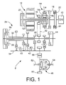
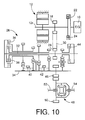
- a hybrid drive system 8 for a front-engine front-drive hybrid drive motor vehicle is installed on the motor vehicle such that various axes of the hybrid drive system 8 are substantially parallel to the transverse or lateral direction (width direction) of the motor vehicle.
- the hybrid drive system 8 includes an engine 10 such as an internal combustion engine operated by combustion of a fuel, a motor/generator 12 functioning as an electric motor and an electric generator, and a planetary gear device 14 of single pinion type.
- the planetary gear device 14 functions as a synthesizing/distributing mechanism for mechanically synthesizing and distributing a force.
- the planetary gear device 14 includes a first rotary element in the form of a ring gear 14r connected to the engine 10 through a first clutch 16, a second rotary element in the form of a sun gear 14s connected to a rotor shaft 12r of the motor/generator 12, and a third rotary element in the form of a carrier 14c which has an integrally formed driving sprocket 18 functioning as an output member.
- the sun gear 14s and the carrier 14c are connected to each other by a second clutch 20.
- An output of the engine 10 is transferred to the first clutch 16 through a flywheel 22 and a damper 24.
- the flywheel 22 serves to reduce speed and torque variations of the engine 10.
- the damper 24 includes a suitable elastic member such as a spring or a rubber member.
- the first and second clutches 16, 20 are friction type multiple-disk clutches, each of which is operated between engaged and released states thereof by a hydraulic actuator.
- the driving sprocket 18 is connected through a chain 30 to a driven sprocket 29 which functions as an input member of an automatic transmission 26.
- the automatic transmission 26 is a parallel two-axes type transmission having a first or input shaft 32 on which the driven sprocket 28 is provided, and a second or output shaft 34 parallel to the first shaft 32.
- the automatic transmission 26 has four pairs of mutually meshing gears for forward driving of the vehicle, and a pair of gears connected through an idler gear for reverse running of the vehicle.
- the automatic transmission 26 includes two frictionally coupling clutches 36, 38 operated by respective hydraulic actuators, and two positive or claw clutches 40, 42 operated by respective hydraulic actuators.
- the automatic transmission 26 is selectively placed in one of a neutral position and four forward-drive positions.
- the automatic transmission 26 further includes a frictionally coupling clutch 44 operated by a hydraulic actuator for establishing a reverse-drive position.
- the second or output shaft 34 has an output gear 46 mounted thereon, which meshes with a ring gear 50 of a bevel gear type differential gear device 48.
- the ring gear 50 functions as an input member of the differential gear device 48.
- Power transferred to the output gear 46 is distributed to right and left drive wheels (front wheels) of the vehicle through a pair of output shafts 52, 54 of the differential gear device 48.
- a portion corresponding to the lower half of the second shaft 34 is not shown except for the output gear 46, since the assembly including the second shaft 34 is symmetrical with respect to the axis of the second shaft 34.
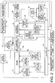
- a control system for the hybrid vehicle drive system 8 there is shown a control system for the hybrid vehicle drive system 8.
- thick solid lines indicate mechanical connections, while thin solid lines indicate electric connections.
- the motor/generator 12, planetary gear mechanism 14 and first and second clutches 16, 20 cooperate to constitute an electrically controlled torque converter 58.
- the differential gear device 48 constitutes a major portion of a speed reducing device 60 shown in Fig. 2, and the front drive wheels constitute a major portion of drive means 62 also shown in Fig. 2.
- the operating states of the engine 10 are controlled by a fuel injection actuator 66, a throttle actuator 68, an ignition actuator 70, and an intake and exhaust valve actuator 72. These actuators 66, 68, 70, 72 are controlled by a controller 64, to control the engine 10.
- the motor/generator 12 is connected to an electric energy storage device 76 such as a battery or capacitor through a motor/generator control device 74 such as an inverter.
- the motor/generator control device 74 is controlled by the controller 64, so that the motor/generator 12 is placed in one of a DRIVE state, a CHARGING state, and a NON-LOAD or FREE state.
- the motor/generator 12 In the DRIVE state, the motor/generator 12 is operated as an electric motor to provide a predetermined torque for driving the vehicle, with an electric energy being supplied to the electric motor from the electric energy storage device 74.
- the motor/generator 12 In the CHARGING state, the motor/generator 12 is operated as an electric generator or dynamo, by regenerative braking (i.e., electrical braking torque of the motor/generator 12 per se), so as to charge the electric energy storage device 76 with an electric energy.
- regenerative braking i.e., electrical braking torque of the motor/generator 12 per se
- the motor/generator 12 In the NON-LOAD or FREE state, the motor/generator 12 is placed in a non-load condition permitting free rotation of the rotor shaft 12r.
- the hydraulic actuators for the first and second clutches 16, 20 are controlled by the controller 64 through respective solenoid-operated valves, so that these clutches 16, 20 are selectively placed in their engaged and released states, for selective connection and disconnection between the engine 10 and the ring gear 14r, and between the sun gear 14s and the carrier 14c.
- the automatic transmission 26 has a parking position, a neutral position "N", a rear drive position “REV”, and a plurality of forward drive positions “FWD”, namely, first-speed, second-speed, third-speed and fourth-speed positions "1st", “2nd", “3rd” and "4th".
- the neutral position "N”, rear drive position “REV” and forward drive positions "FWD” are selectively established by a FWD/N/REV selecting actuator 82 under the control of the controller 64, through a hydraulic circuit including a manual shift valve which is mechanically connected to a shift lever 80. As indicated in Fig.
- the shift lever 80 has a total of five operating positions, parking position "P”, reverse position “R”, neutral position “N”, forward drive position “D”, and drive source brake position "B". With the shift lever 80 placed in the neutral position "N”, the automatic transmission 26 is shifted to the neutral position "N”. With the shift lever 80 placed in the reverse position "R”, the automatic transmission 26 is shifted to the rear drive position "REV”.
- the currently selected position S H of the shift lever 80 is detected by a shift position switch 84. Namely, the output signal of the shift position switch 84 represents the selected position S H of the shift lever 80.
- the automatic transmission 26 is automatically shifted to any one of the forward drive positions by a speed ratio changing actuator 86 under the control of the controller 64.
- the speed ratio changing actuators 76 include solenoid-operated valves for establishing a selected one of combinations of the engaged and released states of the hydraulically operated frictionally coupling clutches 36, 38 and positive clutches 40, 42. Described more specifically, one of the forward drive positions "1st", “2nd”, “3rd” and “4th” is selected on the basis of the operating amount ⁇ AC of an accelerator pedal and a running speed V of the vehicle, and according to predetermined shift patterns which are relationships between these parameters ⁇ AC and V.
- the shift lever 80 placed in the parking position "P"
- the automatic transmission 26 is shifted to the parking position by a parking shift actuator 90. In the parking position, a parking brake is applied to the wheels of the vehicle.
- the drive source brake position "B" of the shift lever 80 is adjacent to the forward drive position "D".
- the shift lever 80 may be inclined in a direction perpendicular to the shifting direction in which the positions "P", “R”, “N”, “D” and “B” are selected. That is, the shift lever 80 placed in the drive source brake position “B” may be inclined to right and left positions indicated by circles of broken lines in Fig. 3.
- the movements of the shift lever 80 to these right and left positions in the drive source brake position "B” are detected by an UP-DOWN switch 88, an output signal of which is sent to the controller 64 each time the shift lever 80 is inclined to the right or left position in the drive source brake position "B".
- the shift lever 80 functions as manually operated means for selecting one of a plurality of different degrees of drive source brake application to the motor vehicle.
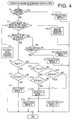
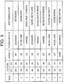
- the controller 64 includes a microcomputer incorporating a central processing unit (CPU), a random-access memory (RAM), and a read-only memory (ROM), and is adapted to control the hybrid drive system 8 according to a predetermined control program, more specifically, select one of nine operation modes indicated in Fig. 5, according to an operation mode determining sub-routine illustrated in the flow chart of Fig. 4 by way of example, and operate the hybrid drive system 8 in the selected operation mode.
- CPU central processing unit
- RAM random-access memory
- ROM read-only memory
- the controller 64 receives various signals from various detectors, such as signals indicative of: torque T E and speed N E of the engine 10; torque T M and speed N M of the motor/generator 12; input shaft speed Ni of the automatic transmission 26; output shaft speed No of the automatic transmission 26 (which speed No can be used to calculate the running speed V of the vehicle); operating amount ⁇ AC of the accelerator pedal; amount SOC of electric energy stored in the electric energy storage device 76; operating state of a brake system (operating state of a brake pedal); currently selected position S H of the shift lever 80; and operator's desired degree of drive source brake application as obtained from the output signals of the UP-DOWN switch 88.
- various detectors such as signals indicative of: torque T E and speed N E of the engine 10; torque T M and speed N M of the motor/generator 12; input shaft speed Ni of the automatic transmission 26; output shaft speed No of the automatic transmission 26 (which speed No can be used to calculate the running speed V of the vehicle); operating amount ⁇ AC of the accelerator pedal; amount SOC of electric energy
- the engine torque T E can be obtained from the opening angle of the throttle valve or fuel injection amount, while the motor torque T M can be obtained from the electric current of the electric motor 12 when the motor/generator is operated as the electric motor.
- the stored electric energy amount SOC can be obtained from the electric current or charging efficiency of the electric generator 12 when the motor/generator is operated as the electric generator to charge the storage device 76.
- step S1 The operation mode determining sub-routine of Fig. 4 is initiated with step S1 to determine whether there exists a command requiring the engine 10 to be started for driving the vehicle with the engine 10 used as the drive power source or for operating the motor/generator 12 for charging the electric energy storage device 76. If an affirmative decision (YES) is obtained in step S1, the control flow goes to step S2 to select an operation mode 9. In this operation mode 9, the first and second clutches 16 and 20 are both engaged (turned ON) as indicated in Fig. 5, and the motor/generator 12 is operated to start the engine 10 through the planetary gear device 14, with the fuel injection amount and other conditions of the engine 10 being suitably controlled.
- this operation mode 9 When this operation mode 9 is selected while the vehicle is stationary, the starting of the engine 10 is effected with the automatic transmission 26 placed in the neutral position.
- the operation mode 9 is selected during running of the vehicle with only the motor/generator 12 as the drive power source as in an operation mode 1 in which the first clutch 16 is in the released state, the first clutch 16 is engaged, and the motor/generator 12 is operated so as to provide an output which is larger than the output necessary to drive the vehicle, by a given surplus output of the motor/generator 12.
- the operation mode 9 eliminates an exclusive starter such as an electric motor provided for the sole purpose of starting the engine, and is therefore effective to reduce the required number of components of the hybrid drive system 8, leading to an accordingly reduced cost of manufacture thereof.
- step S1 determines whether the accelerator pedal is not depressed, that is, whether the operating amount ⁇ AC is smaller than a predetermined threshold which is substantially zero. If the accelerator pedal is off, the control flow goes to step R2. If the accelerator pedal is depressed, the control flow goes to step S5 of the sub-routine of Fig. 4. Step R2 is provided to determine whether the brake pedal is depressed.
- step R2 This determination may be made on the basis of an output signal of a brake switch provided to detect an operation of the brake pedal. If an affirmative decision (YES) is obtained in step R2, the control flow goes to step R3. If a negative decision (NO) is obtained in step R2, step R5 is implemented to determine whether the currently selected position S H of the shift lever 80 is the drive source brake position "B". If the shift lever 80 is placed in the engine braking position "B", the control flow goes to step S4-2 of the sub-routine of Fig. 4, to effect drive source brake control. If the shift lever 80 is not placed in the drive source brake position "B", the control flow goes to step S5 of Fig. 4.
- Step R3 which is implemented when the brake pedal is depressed is provided to determine whether the currently selected position S H of the shift lever 80 is either the forward drive position "D" or the drive source brake position "B". If a negative decision (NO) is obtained in step R3, the control flow goes to step S5 of Fig. 4. If an affirmative decision (YES) is obtained in step R3, that is, if the shift lever 80 is currently placed in the forward drive position "D” or drive source brake position "B", the control flow goes to step R4 to determine whether the electric energy amount SOC stored in the electric energy storage device 76 is smaller than a predetermined upper limit A2. If an affirmative decision (YES) is obtained in step R4, the control flow goes to step S4-1 of Fig. 4, to effect regenerative braking control.
- the upper limit A2 is a maximum amount of the electric energy currently stored in the storage device 76, below which the storage device 76 is permitted to be charged by the electric generator 12. This upper limit A2 is determined by the charging and discharging efficiencies of the storage device 76. For example, the upper limit A2 is selected to be about 80% of the full capacity of the storage device 76.
- step Q1-1 is implemented to select an operation mode 6.
- step Q1-1 is followed by step Q1-2 in which the electric energy generated by the electric generator 12 is controlled depending upon the depression force acting on the brake pedal.
- the first clutch 16 is released (turned OFF) and the second clutch 20 is engaged (turned ON), while the engine 10 is turned OFF, and the motor/generator 12 is placed in the CHARGING state, as indicated in Fig. 5, whereby the motor/generator 12 is operated as the electric generator by a kinetic energy of the motor vehicle, so as to charge the electric energy storage device 76 while applying a regenerative brake to the motor vehicle.
- the regenerative braking reduces the required amount of operation of the brake pedal by the vehicle operator, and facilitates the control of the vehicle running. Since the engine 10 is disconnected from the planetary gear device 14 with the first clutch 16 placed in the released state, the energy loss of the vehicle due to the drag resistance of the engine 10 is prevented in the operation mode 6. Further, since the operation mode 6 is selected when the stored electric energy amount SOC is smaller than the upper limit A2, the electric energy storage device 76 is protected from excessive charging and resulting deterioration of its charging and discharging efficiencies.
- the motor/generator controller 74 is controlled to control the electric generator 12 so that the electric energy generated by the electric generator 12 increases with an increase in the depression force acting on the brake pedal.
- the regenerative braking torque corresponding to the generated electric energy increases with the brake pedal depression force.
- the regenerative brake force based on the regenerative braking torque is applied to the motor vehicle.
- a brake based on this regenerative brake force in the regenerative braking mode as well as an engine brake in the engine braking mode is considered to be a "drive source brake" applied to the vehicle.
- step Q2-1 is implemented to determine whether the electric energy amount SOC currently stored in the storage device 76 is smaller than the upper limit A2. If an affirmative decision (YES) is obtained in step Q2-1, it means that the storage device 76 can be charged. In this case, step Q2-2 and the following steps are implemented to control the electricity generation by the electric generator 12 for applying a regenerative brake to the vehicle. If a negative decision (NO) is obtained in step Q2-1, the control flow goes to step Q2-7 and the following steps to apply an engine brake to the vehicle.
- controller 64 assigned to implement step Q2-1 serves as drive source brake selecting means for selecting the regenerative braking mode (operation mode 6) or the engine braking mode (operation mode 8), depending upon the electric energy amount SOC stored in the storage device 76.
- Step Q2-2 is implemented to select the operation mode 6 (regenerative braking mode) as in step Q1-1.
- Step Q2-2 is followed by step Q2-3 in which the automatic transmission 26 is held in a predetermined position, for example, the third-speed position "3rd” or the position whose speed ratio is next higher than the position selected with the shift lever 80 placed in the forward drive position "D".
- the third-speed position "3rd” the power loss is relatively small, and the electric generator 12 is suitably driven by the kinetic energy of the vehicle.
- Step Q2-3 is followed by step Q2-4 to determine the desired degree of regenerative brake application to the vehicle, on the basis of the output signals of the UP-DOWN switch 88, namely, the operations of the shift lever 80 to the right and left (positive and negative) positions when the shift lever 80 is placed in the drive source brake position "B".
- the control flow goes to step Q2-5 to select one of regenerative braking data maps which corresponds to the determined degree of regenerative brake application.
- Each regenerative braking data map is a relationship between the regenerative braking torque and the speed N M of the motor/generator 12.
- the electric current of the electric generator 12 is controlled on the basis of the speed N M and according to the selected regenerative braking data map, so that the electric generator 12 provides the regenerative braking torque corresponding to the speed N M .
- regenerative braking data maps are provided as indicated in Figs. 9A, 9B, 9C and 9D, which correspond to the four forward drive positions of the automatic transmission 26.
- These data maps are formulated so that the electric generator 12 provides the regenerative brake force which is substantially the same as the engine brake force provided by the engine 10.
- the data map Map 1 of Fig. 9A corresponds to the fourth-speed position "4th" whose speed ratio is the smallest, while the data map Map 2 of Fig. 9B corresponds to the third-speed position "3rd" whose speed ratio is the next smallest.
- the four regenerative braking data maps shown in Figs. 9A-9D are formulated on the assumption that the automatic transmission 26 is held in the third-speed position "3rd" in step Q2-3.
- the data maps are stored in the ROM of the controller 64.
- One-dot chain lines in Figs. 9A-9D represent the maximum regenerative braking torque.
- controller 64 assigned to implement step Q2-2 for selecting the regenerative braking mode (operation mode 6) serves as regenerative braking control means for permitting the motor/generator to be driven as the electric generator by a kinetic energy of the vehicle to charge the electric energy storage device 76 and apply the regenerative brake to the vehicle. It will also be understood that a portion of the controller 64 assigned to implement steps Q2-4, Q2-5 and Q2-6 serves as electricity generation control means for controlling the electric energy generated by the electric generator, depending upon the degree of application of the drive source brake selected by the shift lever 88.
- Step Q2-7 which is implemented if the negative decision (NO) is obtained in step Q2-1 is provided to select an operation mode 8 (engine braking mode).
- the operation mode 8 the first and second clutches 16, 20 are both engaged (turned ON), as indicated in Fig. 5, and the motor/generator 12 is placed in the NON-LOAD state. Further, the engine 10 is turned OFF, that is, the throttle valve is closed and the fuel injection amount is zeroed. As a result, an engine brake due to the drag resistance of the engine 10 is applied to the vehicle, whereby the required amount of operation of the brake pedal by the vehicle operator is reduced, facilitating the control of the vehicle running. Since the motor/generator 12 is placed in the NON-LOAD state and permitted to rotate freely in the operation mode 8, the electric energy storage device 76 is protected from excessive charging and resulting deterioration of its charging and discharging efficiencies.
- a portion of the controller 64 assigned to implement step Q2-7 for selecting the engine braking mode serves as engine braking control means for permitting the engine to be driven by a kinetic energy of the vehicle to apply an engine brake to the vehicle as the drive source brake.
- Step Q2-7 is followed by step Q2-8 to determine the desired degree of engine brake application to the vehicle, on the basis of the output signals of the UP-DOWN switch 88, as in step Q2-4. Then, the control flow goes to step Q2-8 to select one of the forward drive positions of the automatic transmission 26 which corresponds to the determined degree of engine braking.
- Step Q2-9 is followed by step Q2-10 in which the automatic transmission 26 is shifted to the selected forward drive position.
- the brake force produced by the engine 10 increases with an increase in the speed N E of the engine 10, namely, with an increase in the speed ratio of the automatic transmission 26. Therefore, since the position to which the automatic transmission 26 is shifted in step Q2-9 is selected depending upon the degree of engine braking desired by the vehicle operator, the engine brake force desired by the vehicle operator can be obtained in the engine braking mode.
- controller 64 assigned to implement steps Q2-8, Q2-9 and Q2-10 serves as engine brake shift control means for shifting the automatic transmission 26 so as to change the speed ratio thereof depending upon the degree of application of the drive source brake selected by the shift lever (88), so that an engine brake force which is produced by operation of the engine by the kinetic energy and which is applied to the vehicle is controlled depending upon the currently established speed ratio of the automatic transmission.
- step S5 is implemented if neither the regenerative braking nor the engine braking is required.
- Step S5 is provided to determine whether the vehicle is required to be started by operation of the engine 10. This determination may be effected by determining whether the vehicle is in a temporary stop during running of the vehicle with the engine 10 used as the drive power source as in an operation mode 3 (which will be described). For instance, the temporary stopping of the vehicle can be detected by checking if the output speed No of the automatic transmission 26 is zero. Namely, the output speed No is zero when the vehicle is stationary.
- step S5 If an affirmative decision (YES) is obtained in step S5, the control flow goes to step S6 to determine whether the accelerator pedal is in a depressed state , more specifically, whether the operation amount ⁇ AC of the accelerator pedal is larger than a predetermined lower limit which is close to zero but larger than zero. If an affirmative decision (YES) is obtained in step S6, the control flow goes to step S7 to select an operation mode 5. If a negative decision (NO) is obtained in step S6, the control flow goes to step S8 to select an operation mode 7.
- the first clutch 16 is engaged (turned ON) and the second clutch 20 is released (turned OFF), and the engine 10 is operated, as indicated in Fig. 5, whereby the vehicle is started by the engine 10, with the regenerative braking torque of the motor/generator 12 being suitably controlled.
- the torque of the motor/generator 12 is controlled to be equal to a half of the engine torque T E , so that the torque about 1.5 times the engine torque T E is produced from the carrier 14c of the planetary gear device 14.
- the vehicle is started with a torque as large as (1 + ⁇ )/ ⁇ times the torque of the motor/generator 12. If the motor/generator 12 is held in the NON-LOAD state with no current applied to the motor, the output of the carrier 14c is zeroed with the rotor shaft 12r merely rotating in the reverse direction, whereby the vehicle is held stationary.
- the planetary gear device 14 functions as a vehicle start clutch and a torque booster.
- the motor torque T M regenerative braking torque
- the vehicle can be smoothly started with the output torque which is (1 + ⁇ ) times the engine torque T E .
- the motor/generator 12 used in the present hybrid drive system 8 has a torque capacity which is about ⁇ times the maximum torque of the engine 10. Namely, the torque capacity and size of the motor/generator 12 are minimized to minimize the size and cost of manufacture of the hybrid drive system 8, while assuring the required torque.
- the present hybrid drive system 8 is further adapted so that the opening angle of the throttle valve and the fuel injection amount are increased with an increase in the motor torque T M , for preventing stalling of the engine 10 due to a drop of the engine speed N E due to an increase in the reaction force of the motor/generator 12.
- step S8 the first clutch 16 is engaged (turned ON) and the second clutch 20 is released (turned OFF), and the engine 10 is operated while the motor/generator 12 is placed in the NON-LOAD state so that the hybrid drive system 8 is placed in an electrically neutral state, as indicated in Fig. 5.
- this operation mode 7 the output of the carrier 14c is zeroed with the rotor shaft 12r of the motor/generator 12 rotating freely in the reverse direction.
- step S5 If a negative decision (NO) is obtained in step S5, that is, if the starting of the vehicle by the engine 10 is not required, the control flow goes to step S9 to determine whether a currently required output Pd of the hybrid drive system 8 is equal to or smaller than a predetermined first threshold P1.
- the currently required output Pd is an output of the hybrid drive system 8 required to drive the vehicle against a running resistance. This currently required output Pd is calculated according to a predetermined data map or equation, on the basis of the operating amount ⁇ AC of the accelerator pedal, a rate of change of this value ⁇ AC , or the currently established operating position of the automatic transmission 26.
- the predetermined first threshold P1 is a boundary value of the output above which the vehicle is driven with only the engine 10 used as the drive power source and below which the vehicle is driven with only the motor/generator 12 as the drive power source.
- the vehicle is considered to be in a medium-load or high-load running state if the currently required output Pd is larger than the first threshold value P1, and in a low-load running state if the currently required output Pd is equal to or smaller than the first threshold value P1.
- the first threshold value P1 is determined by experiments, so as to minimize the exhaust gas emissions and the fuel consumption, depending upon the energy efficiency during running of the vehicle (in which the electric energy storage device 75 may be charged by operation of the engine 10).
- step S10 determines whether the stored electric energy amount SOC is equal to or smaller than a predetermined lower limit A1. If an affirmative decision (YES) is obtained in step S10, the control flow goes to step S11 to select an operation mode 1. If a negative decision (NO) is obtained in step S10, the control flow goes to step S12 to select an operation mode 3.
- the lower limit A1 is a lower limit of the stored electric energy amount SOC above which the electric energy stored in the storage device 76 can be used to operate the motor/generator 12 as the drive power source.
- the lower limit A1 is determined depending upon the charging and discharging efficiencies of the storage device 76. For instance, the lower limit A1 is about 70% of the full capacity of the storage device 76.
- step S11 the first clutch 16 is released (turned OFF) and the second clutch 20 is engaged (turned ON), and the engine 10 is turned OFF, while the motor/generator 12 is operated so as to provide the currently required output Pd, as indicated in Fig. 5, so that the vehicle is driven with only the motor/generator 12 used as the drive power source.
- the engine 10 is disconnected from the planetary gear device 14, so that the energy loss due to the drag resistance of the engine 10 is prevented as in the operation mode 6, and the motor can be suitably operated with high efficiency with the automatic transmission 26 being suitably shifted.
- the operation mode 1 is selected, that is, the motor/generator 12 is used as the drive power source, when the currently required output Pd is equal to or smaller than the first threshold value P1 while the electric energy amount SOC stored in the storage device 76 is equal to or larger than the lower limit A1.
- the energy efficiency is higher and the fuel consumption and the amount of exhaust gas emissions can be made smaller when the vehicle is driven by the motor/generator 12 (in the operation mode 1) than when the vehicle is driven by the engine 10 (as in operation mode 2).
- the electric energy storage device 76 is prevented from excessive discharging with the stored energy amount SOC falling below the lower limit A1, which would result in deterioration of the charging and discharging efficiencies of the storage device 76.
- step S12 the first and second clutches 16, 20 are both engaged (turned ON), and the engine 10 is turned ON, while the motor/generator 12 is placed in the CHARGING state to charge the electric energy storage device 76 with regenerative braking, as indicated in Fig. 5, whereby the vehicle is driven by the output of the engine 10 while the electric energy storage device 76 is charged with the electric energy generated by the motor/generator 12.
- the engine 10 is operated so as to provide an output larger than the currently required output Pd, and the electric current of the motor/generator 12 is controlled so that a surplus output of the engine 10 is consumed by the motor/generator 12 to charge the storage device 76.
- step S9 If a negative decision (NO) is obtained in step S9, that is, if the currently required output Pd is larger than the first threshold value P1, the control flow goes to step S13 to determine whether the currently required output Pd is smaller than a predetermined second threshold P2 which is larger than the first threshold P1, that is, whether the currently required output Pd is larger than the first threshold P1 and smaller than the second threshold P2, namely, within a predetermined range between P1 and P2.
- This second threshold value P2 is a boundary value of the output below which the vehicle is driven with only the engine 10 used as the drive power source and above which the vehicle is driven with both the engine 10 and the motor/generator 12 as the drive power source.
- the vehicle is considered to be in the medium-load running state if the currently required output Pd is smaller than the second threshold value P2, and in the high-load running state if the currently required output Pd is equal to or larger than the second threshold value P2.
- the second threshold value P2 is determined by experiments, so as to minimize the exhaust gas emissions and the fuel consumption, depending upon the energy efficiency during running of the vehicle (in which the electric energy storage device 76 may be charged by operation of the engine 10).
- step S13 If the currently required output Pd is larger than the first threshold value P1 and smaller than the second threshold value P2, that is, if an affirmative decision (YES) is obtained in step S13, the control flow goes to step S14 to determine whether the stored electric energy amount SOC is equal to or larger than the above-indicated lower limit A1. If an affirmative decision (YES) is obtained in step S14, the control flow goes to step S15 to select an operation mode 2. If a negative decision (NO) is obtained in step S14, the control flow goes to step S12 to select the operation mode 3 discussed above.
- step S13 If the currently required output Pd is equal to or larger than the second threshold P2, that is, if a negative decision (NO) is obtained in step S13, the control flow goes to step S16 to determine whether the stored electric energy amount SOC is equal to or larger than the lower limit A1. If an affirmative decision (YES) is obtained in step S16, the control flow goes to step S17 to select an operation mode 4. If a negative decision (NO) is obtained in step S16, the control flow goes to step S15 to select the operation mode 2.
- step S15 the first and second clutches 16, 20 are both engaged (turned ON), and the engine 10 is operated so as to produce the currently required output Pd, while the motor/generator 12 is placed in the NON-LOAD state, as indicated in Fig. 5, whereby the vehicle is driven with only the engine 10 used as the drive power source.
- step S17 the first and second clutches 16, 20 are both engaged (turned ON), and the engine 10 and the motor/generator 12 are operated, as indicated in Fig. 5, whereby the vehicle is driven with both the engine 10 and the motor/generator 12 used as the drive power source.
- this operation mode 4 selected when the currently required output Pd is equal to the second threshold P2 or larger the engine 10 and the motor/generator 12 are both operated as the drive power sources to drive the vehicle, so that the energy efficiency is less likely to be lowered than in the operation mode 1 or 2 in which either the engine 10 or the motor/generator 12 is used as the drive power source.
- the fuel consumption and the exhaust gas emission can be made lower in this operation mode 4 than in the operation mode 1 or 2 when the currently required output Pd is equal to P2 or larger.
- the operation mode 4 is selected only when the stored electric energy amount SOC is equal to or larger than the lower limit A1, the electric energy storage device 76 is protected from excessive discharging with the stored energy amount SOC falling below the lower limit A1, which would result in deterioration of the charging and discharging efficiencies of the storage device 76.
- the operation modes 1-4 are selected in the following running states of the vehicle.
- the operation mode 1 is selected in step S11 to drive the vehicle with only the motor/generator 12 as the drive power source if the vehicle is in the low-load running state with the currently required output Pd being equal to or smaller than the first threshold P1.
- the operation mode 2 is selected in step S15 to drive the vehicle with only the engine 10 as the drive power source if the vehicle is in the medium-load running state with the currently required output Pd being larger than the first threshold P1 and smaller than the second threshold P2, and the operation mode 4 is selected in step S17 to drive the vehicle with the engine 10 and the motor/generator 12 as the drive power sources if the vehicle is in the high-load running state with the currently required output Pd being equal to or larger than the second threshold P2.
- the operation mode 3 is selected in step S12 to drive the vehicle with only the engine 10 as the drive power source while at the same time charging the electric energy storage device 76 if the vehicle is in the medium-load running state with the currently required output Pd being smaller than the second threshold P2, and the operation mode 2 is selected in step S15 to drive the vehicle with only the engine 10 without charging the storage device 76 if the vehicle is in the high-load running state with the currently required output Pd being equal to or larger than the second threshold P2.
- the operation mode 2 is selected in step S15 in the following two cases: 1) when the vehicle is in the medium-load running state wherein the currently required output Pd is larger than the first threshold P1 and smaller than the second threshold P2, while the stored electric energy amount SOC is not smaller than the lower limit A1; and 2) when the vehicle is in the high-load running state wherein the currently required output Pd is equal to or larger than the second threshold P2, while the stored electric energy amount SOC is smaller than the lower limit A1.
- the energy efficiency is generally higher when the vehicle is driven by the engine 10 than when the vehicle is driven by the motor/generator 12. Accordingly, the fuel consumption and exhaust gas emission can be made smaller in the operation mode 2 than in the operation mode 1.
- the operation mode 4 In the high-load running state, it is generally desirable to select the operation mode 4 in which the vehicle is driven by both of the engine 10 and the motor/generator 12.
- the electric energy amount SOC stored in the electric energy storage device 76 is smaller than the lower limit A1
- step Q2-2 is implemented to select the operation mode 6, namely, the regenerative braking mode, if the electric energy amount SOC stored in the storage device 76 is smaller than the upper limit A2.
- the regenerative braking mode a drive source brake based on the regenerative braking of the motor/generator 12 is applied to the vehicle.
- the force of the drive source brake based on the regenerative braking is controlled according to the regenerative braking data map which is selected depending upon the degree of drive source braking (regenerative braking) desired by the vehicle operator.
- the amount of electric energy generated by the motor/generator 12 as the electric generator is controlled depending upon the operations of the shift lever 80 to the right and left positions while it is placed in the drive source brake position "B". These operations of the shift lever 80 indicate the operator's desired degree of the drive source brake application (regenerative brake application in step Q-2-6).
- the regenerative braking mode rather than the engine braking mode is established, and the automatic transmission 26 is kept in the predetermined forward drive position (e.g., third-speed position "3rd"), while the data map for determining the regenerative braking force is selected depending upon the desired degree of the regenerative brake application (drive source brake application as desired by the vehicle operator).
- the actual generative brake force can be suitably controlled with a higher response to the operator's desired degree of the regenerative brake application (drive source brake application), than in the engine braking control according to steps Q2-7 through Q2-10 in which the automatic transmission 26 is shifted to the position corresponding to the operator/s desired degree of the engine brake application.
- the engine braking control is effected according to steps Q2-8 through Q2-10, so that an engine brake to be applied to the vehicle is controlled by the currently selected position or speed ratio of the automatic transmission 26. Namely, the engine brake is controlled by shifting the transmission to the appropriate position corresponding to the operator's desired degree of the engine brake application.
- the motor/generator 12 is protected from excessive charging and resulting deterioration of the charging and discharging efficiencies.
- the regenerative brake produced by the motor/generator 12 in the regenerative brake control according to steps Q2-2 through Q2-6 is controlled to be substantially equal to the engine brake produced by the engine 10 and controlled by the automatic transmission 12. Accordingly, the present hybrid drive system 8 does not suffer from a difference in the drive source brake force due to the selective use of the engine brake and the regenerative brake, which difference would be undesirable to the vehicle operator who does not generally distinguish the regenerative brake and the engine brake from each other.
- the outputs of the engine 10 and the motor/generator 12 are synthesized or distributed by the planetary gear device 14.
- the principle of the present embodiment is applicable to various other types of hybrid drive system, such as a hybrid drive system according to a second embodiment shown in Fig. 10, which does not include the planetary gear device 14 and in which the rotor shaft 12r of the motor/generator 12 and the engine 10 are directly connected to each other.
Landscapes
- Engineering & Computer Science (AREA)
- Mechanical Engineering (AREA)
- Transportation (AREA)
- Chemical & Material Sciences (AREA)
- Combustion & Propulsion (AREA)
- Power Engineering (AREA)
- Life Sciences & Earth Sciences (AREA)
- Sustainable Development (AREA)
- Sustainable Energy (AREA)
- General Engineering & Computer Science (AREA)
- Electric Propulsion And Braking For Vehicles (AREA)
- Hybrid Electric Vehicles (AREA)
- Control Of Vehicle Engines Or Engines For Specific Uses (AREA)
- Braking Arrangements (AREA)
Applications Claiming Priority (3)
| Application Number | Priority Date | Filing Date | Title |
|---|---|---|---|
| JP89440/96 | 1996-04-11 | ||
| JP8944096 | 1996-04-11 | ||
| JP8089440A JPH09277847A (ja) | 1996-04-11 | 1996-04-11 | ハイブリッド車両のエンジンブレーキ制御装置 |
Publications (3)
| Publication Number | Publication Date |
|---|---|
| EP0800949A2 true EP0800949A2 (de) | 1997-10-15 |
| EP0800949A3 EP0800949A3 (de) | 1998-10-07 |
| EP0800949B1 EP0800949B1 (de) | 2001-06-20 |
Family
ID=13970747
Family Applications (1)
| Application Number | Title | Priority Date | Filing Date |
|---|---|---|---|
| EP97105864A Expired - Lifetime EP0800949B1 (de) | 1996-04-11 | 1997-04-09 | Kontrollvorrichtung für den elektrischen Generator eines Hybridfahrzeuges zur Kontrolle der Bremsenergierückgewinnung in Abhängigkeit von der gewählten Motorbremsart |
Country Status (4)
| Country | Link |
|---|---|
| US (1) | US5839533A (de) |
| EP (1) | EP0800949B1 (de) |
| JP (1) | JPH09277847A (de) |
| DE (1) | DE69705253T2 (de) |
Cited By (27)
| Publication number | Priority date | Publication date | Assignee | Title |
|---|---|---|---|---|
| WO1999033682A3 (de) * | 1997-12-23 | 1999-10-07 | Luk Getriebe Systeme Gmbh | Getriebe |
| EP0913287A3 (de) * | 1997-10-27 | 2000-06-14 | Honda Giken Kogyo Kabushiki Kaisha | Hybridfahrzeug |
| EP0933245A3 (de) * | 1998-02-03 | 2000-12-06 | Honda Giken Kogyo Kabushiki Kaisha | Kontrollsystem für Hybridfahrzeug |
| FR2801253A1 (fr) * | 1999-11-19 | 2001-05-25 | Renault | Procede de recuperation d'energie sur un vehicule en deceleration |
| WO2002006072A1 (de) * | 2000-07-18 | 2002-01-24 | Siemens Aktiengesellschaft | Steuereinheit für ein getriebe und zugehöriges betriebsverfahren |
| GB2386879A (en) * | 2002-03-25 | 2003-10-01 | Ford Motor Co | Regenerative braking system for hybrid electric vehicle |
| EP1375241A1 (de) * | 2002-06-19 | 2004-01-02 | Honda Giken Kogyo Kabushiki Kaisha | Hybridfahrzeugssteuerungsystem |
| EP0930193A3 (de) * | 1998-01-19 | 2004-01-28 | Volkswagen Aktiengesellschaft | Verfahren zum Steuern eines Antriebssytems eines Kraftfahrzeuges mit Schwung-Nutz-Automatik (SNA) |
| WO2004028845A1 (de) * | 2002-09-19 | 2004-04-08 | Luk Lamellen Und Kupplungsbau Beteiligungs Kg | Verfahren, vorrichtung und deren verwendung zum betrieb eines kraftfahrzeuges |
| EP0933246B1 (de) * | 1998-02-03 | 2004-06-30 | Honda Giken Kogyo Kabushiki Kaisha | Regelsystem für ein Hybridfahrzeug |
| EP1142743A3 (de) * | 2000-04-07 | 2005-04-27 | Tochigi Fuji Sangyo Kabushiki Kaisha | Kraftübertragungsvorrichtung und Verfahren zu deren Betrieb |
| US6986399B2 (en) | 2000-04-11 | 2006-01-17 | Ford Global Technologies, Llc | Hybrid electric vehicle with variable displacement engine |
| EP1018451A4 (de) * | 1998-07-21 | 2006-02-15 | Tokyo R & D Kk | Hybridfahrzeug und verfahren zur fahrzeugfahrtregelung |
| DE10041593B4 (de) * | 1999-09-07 | 2006-03-02 | Honda Giken Kogyo K.K. | Steuervorrichtung für ein Hybridfahrzeug, Hybridfahrzeug und Verfahren zur Steuerung eines Bremsvorgangs eines solchen |
| EP1291219A3 (de) * | 2001-09-05 | 2006-04-12 | Hitachi, Ltd. | Hilfsantrieb und damit ausgestattetes Fahrzeug |
| WO2006080570A1 (en) * | 2005-01-31 | 2006-08-03 | Toyota Jidosha Kabushiki Kaisha | Hybrid vehicle and control method of hybrid vehicle |
| WO2007006442A1 (de) * | 2005-07-09 | 2007-01-18 | Bayerische Motoren Werke Aktiengesellschaft | Antriebseinrichtung für ein kraftfahrzeug |
| WO2007039021A1 (de) * | 2005-09-30 | 2007-04-12 | Zf Friedrichshafen Ag | Automatisiertes kfz-schaltgetriebe und verfahren zur schaltsteuerung eines automatisierten kfz-schaltgetriebes |
| US7246672B2 (en) * | 2002-11-29 | 2007-07-24 | Kabushikikaisha Equos Research | Hybrid-vehicle power train |
| CN100366482C (zh) * | 2004-05-14 | 2008-02-06 | 通用汽车公司 | 用于混合车辆的协调的再生和发动机减速制动 |
| EP2127987A1 (de) * | 2008-05-27 | 2009-12-02 | Iveco S.p.A. | Bremsverfahren und Bremsvorrichtung mit Energierückgewinnung, insbesondere für ein mit einem hybriden Antriebssystem ausgerüstetes Fahrzeug |
| WO2010007291A1 (fr) * | 2008-07-18 | 2010-01-21 | Renault S.A.S. | Boite de vitesses hybride a arbres parallelles |
| GB2473962A (en) * | 2009-09-26 | 2011-03-30 | Ford Global Tech Llc | Hybrid vehicle drivetrain with gear change disconnection |
| EP2386436A4 (de) * | 2009-03-24 | 2013-02-27 | Honda Motor Co Ltd | Kraftübertragungsvorrichtung |
| CN103434395A (zh) * | 2013-08-28 | 2013-12-11 | 常熟市海虞镇志宏五金厂 | 汽车制动能回收转化系统 |
| EP2247479A4 (de) * | 2008-03-03 | 2018-02-07 | Nissan Motor Co., Ltd. | Steuerungsvorrichtung und verfahren zur steuerung eines hybridfahrzeugs |
| DE102018208240A1 (de) * | 2018-05-25 | 2019-11-28 | Zf Friedrichshafen Ag | Antriebsstrang, Kraftfahrzeug sowie Verfahren zur Auswahl eines Rekuperationsgrades |
Families Citing this family (118)
| Publication number | Priority date | Publication date | Assignee | Title |
|---|---|---|---|---|
| US6847189B2 (en) * | 1995-05-31 | 2005-01-25 | The Regents Of The University Of California | Method for controlling the operating characteristics of a hybrid electric vehicle |
| US6054844A (en) * | 1998-04-21 | 2000-04-25 | The Regents Of The University Of California | Control method and apparatus for internal combustion engine electric hybrid vehicles |
| JP3050125B2 (ja) * | 1996-05-20 | 2000-06-12 | トヨタ自動車株式会社 | 動力出力装置および動力出力装置の制御方法 |
| JP3520668B2 (ja) * | 1996-06-11 | 2004-04-19 | トヨタ自動車株式会社 | ハイブリッド車両の制御装置 |
| US6387007B1 (en) * | 1997-01-24 | 2002-05-14 | Anthony W. Fini, Jr. | Electromechanical vehicle regeneration system |
| US6216808B1 (en) * | 1997-07-30 | 2001-04-17 | Aisin Seiki Kabushiki Kaisha | Brake control system for an electrically operated vehicle |
| JP3775012B2 (ja) * | 1997-08-29 | 2006-05-17 | アイシン・エィ・ダブリュ株式会社 | 車両用ハイブリッド駆動装置 |
| JP3096447B2 (ja) * | 1997-09-17 | 2000-10-10 | 本田技研工業株式会社 | ハイブリッド車両の制御装置 |
| US6367570B1 (en) | 1997-10-17 | 2002-04-09 | Electromotive Inc. | Hybrid electric vehicle with electric motor providing strategic power assist to load balance internal combustion engine |
| JPH11289610A (ja) * | 1998-04-01 | 1999-10-19 | Nissan Motor Co Ltd | ハイブリッド自動車の補助ブレーキ装置 |
| US6155365A (en) * | 1998-05-12 | 2000-12-05 | Chrysler Corporation | Brake blending strategy for a hybrid vehicle |
| JP3410022B2 (ja) * | 1998-05-20 | 2003-05-26 | 本田技研工業株式会社 | ハイブリッド車両の制御装置 |
| US6554088B2 (en) | 1998-09-14 | 2003-04-29 | Paice Corporation | Hybrid vehicles |
| US6338391B1 (en) | 1999-03-01 | 2002-01-15 | Paice Corporation | Hybrid vehicles incorporating turbochargers |
| US6209672B1 (en) | 1998-09-14 | 2001-04-03 | Paice Corporation | Hybrid vehicle |
| JP2002526326A (ja) * | 1998-10-02 | 2002-08-20 | ルーク ラメレン ウント クツプルングスバウ ベタイリグングス コマンディートゲゼルシャフト | 少なくとも2つの軸、及び、電気機械又は自動的なディスククラッチを有する伝動装置 |
| US6719076B1 (en) * | 1999-02-08 | 2004-04-13 | Toyota Jidosha Kabushiki Kaisha | Vehicle braked by motor torque and method of controlling the vehicle |
| WO2000046063A1 (en) * | 1999-02-08 | 2000-08-10 | Toyota Jidosha Kabushiki Kaisha | Vehicle braked by motor torque and method of controlling the vehicle |
| JP3682685B2 (ja) | 1999-03-10 | 2005-08-10 | スズキ株式会社 | 車両推進装置の制御装置 |
| JP3799866B2 (ja) * | 1999-03-17 | 2006-07-19 | トヨタ自動車株式会社 | ハイブリッド車両の制動力制御装置 |
| JP3644298B2 (ja) | 1999-03-31 | 2005-04-27 | スズキ株式会社 | モータ駆動制御装置 |
| JP3575320B2 (ja) * | 1999-03-31 | 2004-10-13 | スズキ株式会社 | 車両のモータ駆動制御装置 |
| JP3633357B2 (ja) | 1999-03-31 | 2005-03-30 | スズキ株式会社 | 車両のモータ駆動制御装置 |
| JP2000301959A (ja) * | 1999-04-21 | 2000-10-31 | Hitachi Ltd | 自動車の動力伝達装置 |
| JP2001030775A (ja) * | 1999-07-22 | 2001-02-06 | Denso Corp | 車両駆動装置 |
| JP3560863B2 (ja) * | 1999-07-30 | 2004-09-02 | 本田技研工業株式会社 | ハイブリッド車両の制御装置 |
| JP2001099039A (ja) | 1999-09-30 | 2001-04-10 | Suzuki Motor Corp | エンジン結合型モータの制御装置 |
| JP3832701B2 (ja) | 1999-09-30 | 2006-10-11 | スズキ株式会社 | エンジン結合型モータの制御装置 |
| JP3656241B2 (ja) | 1999-09-30 | 2005-06-08 | スズキ株式会社 | エンジン結合型モータの制御装置 |
| JP3656242B2 (ja) | 1999-10-26 | 2005-06-08 | スズキ株式会社 | 車両のモータ制御装置 |
| US6251042B1 (en) * | 1999-11-05 | 2001-06-26 | General Motors Corporation | Hybrid powertrain with an integrated motor/generator |
| DE19963400B4 (de) * | 1999-12-28 | 2010-06-10 | Robert Bosch Gmbh | Verfahren zur Steuerung eines Schaltvorganges in einem Antriebsaggregat für ein Kraftfahrzeug und Antriebsaggregat |
| US7185722B1 (en) * | 2000-02-04 | 2007-03-06 | Hitachi, Ltd. | Power transmission apparatus of motor vehicles |
| US6484833B1 (en) * | 2000-03-17 | 2002-11-26 | General Motors Corporation | Apparatus and method for maintaining state of charge in vehicle operations |
| US6394208B1 (en) | 2000-03-30 | 2002-05-28 | Ford Global Technologies, Inc. | Starter/alternator control strategy to enhance driveability of a low storage requirement hybrid electric vehicle |
| JP3909641B2 (ja) | 2000-04-05 | 2007-04-25 | スズキ株式会社 | ハイブリッド車両の制御装置 |
| JP3820842B2 (ja) | 2000-04-05 | 2006-09-13 | スズキ株式会社 | ハイブリッド車両の制御装置 |
| US6263267B1 (en) | 2000-05-09 | 2001-07-17 | Ford Global Technologies, Inc. | Traction control system for a hybrid electric vehicle |
| JP3838478B2 (ja) | 2000-05-11 | 2006-10-25 | スズキ株式会社 | 車両用発電制御装置 |
| JP3656243B2 (ja) | 2000-06-06 | 2005-06-08 | スズキ株式会社 | ハイブリッド車両の制御装置 |
| JP3904135B2 (ja) | 2000-08-04 | 2007-04-11 | スズキ株式会社 | ハイブリッド車両の制御装置 |
| JP3651772B2 (ja) | 2000-08-04 | 2005-05-25 | スズキ株式会社 | ハイブリッド車両の制御装置 |
| US6709075B1 (en) | 2000-08-07 | 2004-03-23 | Ford Global Technologies, Llc | System and method for braking an electric drive vehicle on a low Mu surface |
| JP3788736B2 (ja) | 2000-12-18 | 2006-06-21 | スズキ株式会社 | エンジンの自動停止始動制御装置 |
| CN100362722C (zh) * | 2001-01-03 | 2008-01-16 | 加利福尼亚大学董事会 | 混合电动车辆及用于控制混合电动车辆的方法及装置 |
| JP4006948B2 (ja) * | 2001-02-14 | 2007-11-14 | スズキ株式会社 | 車両用発電制御装置 |
| US6455947B1 (en) | 2001-02-14 | 2002-09-24 | Bae Systems Controls, Inc. | Power combining apparatus for hybrid electric vehicle |
| JP3772683B2 (ja) | 2001-03-21 | 2006-05-10 | スズキ株式会社 | ハイブリッド車両の制御装置 |
| US6615118B2 (en) * | 2001-03-27 | 2003-09-02 | General Electric Company | Hybrid energy power management system and method |
| US6612245B2 (en) | 2001-03-27 | 2003-09-02 | General Electric Company | Locomotive energy tender |
| US9193268B2 (en) | 2001-03-27 | 2015-11-24 | General Electric Company | Hybrid energy power management system and method |
| US20060005736A1 (en) * | 2001-03-27 | 2006-01-12 | General Electric Company | Hybrid energy off highway vehicle electric power management system and method |
| US6973880B2 (en) | 2001-03-27 | 2005-12-13 | General Electric Company | Hybrid energy off highway vehicle electric power storage system and method |
| US6612246B2 (en) | 2001-03-27 | 2003-09-02 | General Electric Company | Hybrid energy locomotive system and method |
| US7448328B2 (en) * | 2001-03-27 | 2008-11-11 | General Electric Company | Hybrid energy off highway vehicle electric power storage system and method |
| US9151232B2 (en) | 2001-03-27 | 2015-10-06 | General Electric Company | Control system and method |
| US7430967B2 (en) * | 2001-03-27 | 2008-10-07 | General Electric Company | Multimode hybrid energy railway vehicle system and method |
| US6591758B2 (en) | 2001-03-27 | 2003-07-15 | General Electric Company | Hybrid energy locomotive electrical power storage system |
| US7231877B2 (en) * | 2001-03-27 | 2007-06-19 | General Electric Company | Multimode hybrid energy railway vehicle system and method |
| US7086977B2 (en) | 2001-05-03 | 2006-08-08 | Ford Global Technologies, Llc | Transmission arrangements for hybrid electric vehicles |
| JP3679070B2 (ja) * | 2001-06-22 | 2005-08-03 | 本田技研工業株式会社 | 燃料電池自動車の制御装置 |
| JP4205878B2 (ja) * | 2001-08-31 | 2009-01-07 | 本田技研工業株式会社 | ハイブリッド型車両の動力伝達装置及びその制御方法 |
| JP2003172443A (ja) * | 2001-12-10 | 2003-06-20 | Honda Motor Co Ltd | 車両用動力伝達制御装置 |
| JP2003259504A (ja) * | 2002-03-06 | 2003-09-12 | Nissan Motor Co Ltd | 制動制御装置 |
| US6724165B2 (en) * | 2002-03-11 | 2004-04-20 | Vectrix Corporation | Regenerative braking system for an electric vehicle |
| US6753619B2 (en) * | 2002-08-06 | 2004-06-22 | Visteon Global Technologies, Inc. | Fly-wheel-based regenerative energy management system |
| US6687593B1 (en) | 2002-09-06 | 2004-02-03 | Ford Motor Company | Combined regenerative and friction braking system for a vehicle |
| JP3896973B2 (ja) * | 2003-02-25 | 2007-03-22 | 株式会社デンソー | 車両用電気系の管理方法 |
| DE10318738A1 (de) * | 2003-04-25 | 2004-11-11 | Daimlerchrysler Ag | Steuerung eines Elektromotors |
| US7694762B2 (en) * | 2003-09-22 | 2010-04-13 | Ford Global Technologies, Llc | Hybrid vehicle powertrain with improved reverse drive performance |
| US6986727B2 (en) * | 2003-12-23 | 2006-01-17 | Caterpillar Inc. | Retarding control for an electric drive machine |
| DE102004005349A1 (de) * | 2004-02-02 | 2005-08-18 | Fev Motorentechnik Gmbh | Hybridmotor |
| US7322902B2 (en) | 2004-05-10 | 2008-01-29 | Toyota Jidosha Kabushiki Kaisha | Control device for vehicular transmission mechanism |
| US7147239B2 (en) * | 2004-07-01 | 2006-12-12 | Ford Global Technologies, Llc | Wheel creep control of hydraulic hybrid vehicle using regenerative braking |
| GB0515105D0 (en) * | 2004-08-02 | 2005-08-31 | Ford Global Tech Llc | System and method for braking a vehicle |
| US7441845B2 (en) | 2004-09-13 | 2008-10-28 | Ford Global Technologies, Llc | Method for operating multiple axle regenerative braking in an automotive vehicle |
| US7832297B2 (en) | 2005-04-19 | 2010-11-16 | Hewatt Chris B | Method and apparatus for gyroscopic propulsion |
| US7628236B1 (en) * | 2005-08-01 | 2009-12-08 | Brown Albert W | Manually operated electrical control and installation scheme for electric hybrid vehicles |
| US8453772B2 (en) | 2005-08-01 | 2013-06-04 | Albert W. Brown | Manually operated electrical control and installation scheme for electric hybrid vehicles |
| US7261661B2 (en) * | 2005-09-01 | 2007-08-28 | General Motors Corporation | Parallel hybrid transmission having a single motor/generator |
| US7256510B2 (en) * | 2005-12-23 | 2007-08-14 | General Motors Corportion | Hybrid electro-mechanical transmission with single motor/generator and method of control |
| US20070169086A1 (en) * | 2005-12-30 | 2007-07-19 | Siliconmotion Inc. | System and method for updating in-system program |
| US7654355B1 (en) | 2006-01-17 | 2010-02-02 | Williams Kevin R | Flywheel system for use with electric wheels in a hybrid vehicle |
| US20070284170A1 (en) * | 2006-06-13 | 2007-12-13 | Kuras Brian D | Retarding control for hydromechanical drive machine |
| US7576501B2 (en) * | 2006-10-11 | 2009-08-18 | Ford Global Technologies, Llc | Method for controlling a hybrid electric vehicle powertrain with divided power flow paths |
| JP5011500B2 (ja) * | 2007-01-10 | 2012-08-29 | 日産自動車株式会社 | ハイブリッド車両のモータ/ジェネレータ制御装置 |
| DE102007039980A1 (de) * | 2007-08-23 | 2009-02-26 | Volkswagen Ag | Doppelkupplungsgetriebe bzw. Antriebsstrang mit einem derartigen Doppelkupplungsgetriebe |
| US8258727B2 (en) * | 2007-09-10 | 2012-09-04 | International Rectifier Corporation | Regenerative torque shifter |
| FR2921884A1 (fr) * | 2007-10-03 | 2009-04-10 | Peugeot Citroen Automobiles Sa | Procede de pilotage d'une chaine de traction hybride base sur l'etat de charge de la batterie. |
| US20090187298A1 (en) * | 2008-01-18 | 2009-07-23 | Cuppetilli Robert D | Vehicle propulsion arrangement |
| US9545839B2 (en) * | 2008-09-05 | 2017-01-17 | Ford Global Technologies, Llc | Hybrid electric vehicle powertrain with enhanced reverse drive performance |
| DE102008060954B4 (de) * | 2008-12-06 | 2023-03-09 | Bayerische Motoren Werke Aktiengesellschaft | Verfahren zur Regelung bzw. Steuerung des Ladezustands eines elektrischen Energiespeichers eines Hybridfahrzeugs |
| US9434362B2 (en) * | 2010-03-29 | 2016-09-06 | Current Motor Company | System and method to control regenerative braking |
| JP5462057B2 (ja) * | 2010-04-08 | 2014-04-02 | アイシン・エーアイ株式会社 | 車両の動力伝達制御装置 |
| US20110307130A1 (en) * | 2010-05-13 | 2011-12-15 | Coda Automotive, Inc. | Selectable driving modes |
| US20130218386A1 (en) * | 2010-08-04 | 2013-08-22 | Fisker Automotive, Inc. | Vehicle operation mode systems and methods |
| US9162679B2 (en) | 2010-12-23 | 2015-10-20 | Cummins Intellectual Property, Inc. | System and method of vehicle operating condition management |
| US8452509B2 (en) * | 2010-12-23 | 2013-05-28 | Cummins Intellectual Property, Inc. | System and method of vehicle speed-based operational cost optimization |
| CN102555827A (zh) * | 2011-01-01 | 2012-07-11 | 银世德 | 颠簸能汽车 |
| CN103298637B (zh) * | 2011-02-08 | 2016-03-30 | 本田技研工业株式会社 | 混合动力车辆的驱动装置 |
| US9108501B2 (en) * | 2011-07-05 | 2015-08-18 | Ford Global Technologies, Llc | Multi-mode powersplit powertrain for electric vehicle |
| GB201120114D0 (en) * | 2011-11-22 | 2012-01-04 | Land Rover Uk Ltd | Hybrid electric vehicle and method of control thereof |
| DE102012111034B4 (de) * | 2012-11-16 | 2024-08-29 | Dr. Ing. H.C. F. Porsche Aktiengesellschaft | Antriebsstrang eines Kraftfahrzeugs mit Verbrennungsmotor und Starter-Generator |
| US8894526B2 (en) | 2012-12-03 | 2014-11-25 | Ford Global Technologies, Llc | Powertrain for a hybrid electric vehicle |
| JP5896301B2 (ja) * | 2012-12-25 | 2016-03-30 | 三菱自動車工業株式会社 | 回生ブレーキ制御装置 |
| DE102013215114B4 (de) | 2013-08-01 | 2024-04-25 | Zf Friedrichshafen Ag | Hybridantrieb eines Kraftfahrzeugs |
| DE102013021608A1 (de) * | 2013-09-27 | 2015-04-02 | Liebherr-Components Biberach Gmbh | Selbstfahrende Arbeitsmaschine sowie Verfahren zum Abbremsen einer solchen Arbeitsmaschine |
| JP6194810B2 (ja) * | 2014-02-12 | 2017-09-13 | マツダ株式会社 | 車両の制御装置及び制御方法 |
| JP6149751B2 (ja) * | 2014-02-12 | 2017-06-21 | マツダ株式会社 | 車両の制御装置 |
| WO2016151663A1 (ja) * | 2015-03-20 | 2016-09-29 | 日産自動車株式会社 | 車両の回生変速制御装置 |
| JP6641846B2 (ja) * | 2015-09-30 | 2020-02-05 | 三菱自動車工業株式会社 | 回生ブレーキ制御装置 |
| JP2018196166A (ja) * | 2017-05-12 | 2018-12-06 | ヤマハ発動機株式会社 | 電動車両 |
| JP6897512B2 (ja) * | 2017-11-13 | 2021-06-30 | トヨタ自動車株式会社 | ハイブリッド車両の駆動力制御装置 |
| US11760168B2 (en) | 2018-10-03 | 2023-09-19 | Carrier Corporation | Anti-lock tire system |
| CN112334340B (zh) | 2018-10-03 | 2024-11-26 | 开利公司 | 发生器移动控制 |
| KR102574116B1 (ko) * | 2018-11-09 | 2023-09-05 | 현대자동차주식회사 | 차량 및 그 제어 방법 |
| JP7327256B2 (ja) * | 2020-04-10 | 2023-08-16 | トヨタ自動車株式会社 | 電動車両の回生制動制御装置 |
| US12151566B2 (en) | 2021-06-16 | 2024-11-26 | Anthony Wayne Ashton | System providing additional power to extend ranges of electric vehicles |
Family Cites Families (25)
| Publication number | Priority date | Publication date | Assignee | Title |
|---|---|---|---|---|
| US4196587A (en) * | 1978-02-06 | 1980-04-08 | Samuel Shiber | Multi-mode transmission |
| US4591016A (en) * | 1984-03-19 | 1986-05-27 | General Motors Corporation | Brake system in a vehicle hybrid drive arrangement |
| JPS61218853A (ja) * | 1985-03-26 | 1986-09-29 | Aisin Seiki Co Ltd | 自動変速制御装置 |
| US4671577A (en) * | 1985-11-21 | 1987-06-09 | Urban Transportation Development Corporation Ltd. | Combined regenerative and friction braking system for a vehicle |
| US4928227A (en) * | 1987-11-02 | 1990-05-22 | Ford Motor Company | Method for controlling a motor vehicle powertrain |
| JP3163622B2 (ja) * | 1990-07-05 | 2001-05-08 | 日産自動車株式会社 | 電気自動車 |
| US5365431A (en) * | 1991-04-24 | 1994-11-15 | Aisin Aw Co., Ltd. | Control of electric vehicle motors responsive to detected vehicle speed and required total driving force |
| JP3339589B2 (ja) * | 1992-08-04 | 2002-10-28 | 株式会社エクォス・リサーチ | ハイブリッド型車両 |
| JP3168721B2 (ja) * | 1992-08-08 | 2001-05-21 | 日産自動車株式会社 | 電気自動車の走行制御装置 |
| US5392664A (en) * | 1992-08-14 | 1995-02-28 | Gogins; Laird B. | Continuously variable transmission |
| US5343970A (en) * | 1992-09-21 | 1994-09-06 | Severinsky Alex J | Hybrid electric vehicle |
| US5318142A (en) * | 1992-11-05 | 1994-06-07 | Ford Motor Company | Hybrid drive system |
| FR2698831B1 (fr) * | 1992-12-08 | 1995-01-13 | Renault | Dispositif de commande de freinage électrique récupératif sur un véhicule électrique. |
| DE4324010C2 (de) * | 1993-07-17 | 1995-05-11 | Daimler Benz Ag | Verfahren zur Steuerung der Drehmomentabgabe eines ein Fahrzeug antreibenden Hybridantriebes |
| GB9320661D0 (en) * | 1993-10-07 | 1993-11-24 | Lucas Ind Public Limited | Electric vehicle having abs |
| DE4437322B4 (de) * | 1993-10-29 | 2008-02-07 | Volkswagen Ag | Motorbremse bei einem fahrergesteuerten Fahrzeug mit Elektromotor |
| US5492192A (en) * | 1994-08-22 | 1996-02-20 | General Motors Corporation | Electric vehicle with traction control |
| US5644200A (en) * | 1994-10-03 | 1997-07-01 | Yang; Tai-Her | Driving electrical machine speed controlled power combined system and device |
| US5505527A (en) * | 1995-03-16 | 1996-04-09 | The United States Of America As Represented By The Administrator, U.S. Environmental Protection Agency | Anti-lock regenerative braking system |
| US5615933A (en) * | 1995-05-31 | 1997-04-01 | General Motors Corporation | Electric vehicle with regenerative and anti-lock braking |
| JPH0937407A (ja) * | 1995-07-18 | 1997-02-07 | Toyota Motor Corp | 回生制動制御装置 |
| JP3454036B2 (ja) * | 1995-11-13 | 2003-10-06 | トヨタ自動車株式会社 | ハイブリッド駆動装置 |
| US5637987A (en) * | 1995-12-18 | 1997-06-10 | General Motors Corporation | Regenerative vehicle launch |
| US5707115A (en) * | 1996-10-07 | 1998-01-13 | General Motors Corporation | Regenerative braking method |
| JP2007010696A (ja) * | 2005-06-28 | 2007-01-18 | Kyocera Mita Corp | 画像形成装置 |
-
1996
- 1996-04-11 JP JP8089440A patent/JPH09277847A/ja active Pending
-
1997
- 1997-04-09 DE DE69705253T patent/DE69705253T2/de not_active Expired - Fee Related
- 1997-04-09 EP EP97105864A patent/EP0800949B1/de not_active Expired - Lifetime
- 1997-04-10 US US08/834,859 patent/US5839533A/en not_active Expired - Fee Related
Cited By (45)
| Publication number | Priority date | Publication date | Assignee | Title |
|---|---|---|---|---|
| US6186255B1 (en) | 1997-10-27 | 2001-02-13 | Honda Giken Kogyo Kabushiki Kaisha | Hybrid vehicle |
| EP0913287A3 (de) * | 1997-10-27 | 2000-06-14 | Honda Giken Kogyo Kabushiki Kaisha | Hybridfahrzeug |
| ES2222053A1 (es) * | 1997-12-23 | 2005-01-16 | Luk Lamellen Und Kupplungsbau Beteiligungs Kg. | Caja de cambios. |
| GB2348255A (en) * | 1997-12-23 | 2000-09-27 | Luk Lamellen & Kupplungsbau | Gear box |
| WO1999033682A3 (de) * | 1997-12-23 | 1999-10-07 | Luk Getriebe Systeme Gmbh | Getriebe |
| ES2222053B1 (es) * | 1997-12-23 | 2006-03-01 | Luk Lamellen Und Kupplungsbau Beteiligungs Kg. | Caja de cambios. |
| GB2348255B (en) * | 1997-12-23 | 2002-07-03 | Luk Lamellen & Kupplungsbau | Gear box |
| US6591705B1 (en) | 1997-12-23 | 2003-07-15 | Luk Lamellen Und Kupplungsbau Beteiligungs Kg | Transmission |
| EP0930193A3 (de) * | 1998-01-19 | 2004-01-28 | Volkswagen Aktiengesellschaft | Verfahren zum Steuern eines Antriebssytems eines Kraftfahrzeuges mit Schwung-Nutz-Automatik (SNA) |
| EP0933246B1 (de) * | 1998-02-03 | 2004-06-30 | Honda Giken Kogyo Kabushiki Kaisha | Regelsystem für ein Hybridfahrzeug |
| EP0933245A3 (de) * | 1998-02-03 | 2000-12-06 | Honda Giken Kogyo Kabushiki Kaisha | Kontrollsystem für Hybridfahrzeug |
| EP1762416A3 (de) * | 1998-07-21 | 2007-03-21 | TOKYO R&D CO., LTD. | Hybridfahrzeug |
| EP1018451A4 (de) * | 1998-07-21 | 2006-02-15 | Tokyo R & D Kk | Hybridfahrzeug und verfahren zur fahrzeugfahrtregelung |
| DE10041593B4 (de) * | 1999-09-07 | 2006-03-02 | Honda Giken Kogyo K.K. | Steuervorrichtung für ein Hybridfahrzeug, Hybridfahrzeug und Verfahren zur Steuerung eines Bremsvorgangs eines solchen |
| FR2801253A1 (fr) * | 1999-11-19 | 2001-05-25 | Renault | Procede de recuperation d'energie sur un vehicule en deceleration |
| US7086978B2 (en) | 2000-04-07 | 2006-08-08 | Tochigi Fuji Sangyo Kabushiki Kaisha | Power transmission system and operation method therefor |
| EP1142743A3 (de) * | 2000-04-07 | 2005-04-27 | Tochigi Fuji Sangyo Kabushiki Kaisha | Kraftübertragungsvorrichtung und Verfahren zu deren Betrieb |
| US7223191B2 (en) | 2000-04-07 | 2007-05-29 | Tochigi Fuji Sangyo Kabushiki Kaisha | Power transmission system and operation method thereof |
| US6986399B2 (en) | 2000-04-11 | 2006-01-17 | Ford Global Technologies, Llc | Hybrid electric vehicle with variable displacement engine |
| US7240749B2 (en) * | 2000-04-11 | 2007-07-10 | Ford Global Technologies, Llc | Hybrid electric vehicle with variable displacement engine |
| WO2002006072A1 (de) * | 2000-07-18 | 2002-01-24 | Siemens Aktiengesellschaft | Steuereinheit für ein getriebe und zugehöriges betriebsverfahren |
| US6932737B2 (en) | 2000-07-18 | 2005-08-23 | Siemens Aktiengesellschaft | Control unit for a transmission and associated operating method |
| EP1291219A3 (de) * | 2001-09-05 | 2006-04-12 | Hitachi, Ltd. | Hilfsantrieb und damit ausgestattetes Fahrzeug |
| GB2386879A (en) * | 2002-03-25 | 2003-10-01 | Ford Motor Co | Regenerative braking system for hybrid electric vehicle |
| EP1375241A1 (de) * | 2002-06-19 | 2004-01-02 | Honda Giken Kogyo Kabushiki Kaisha | Hybridfahrzeugssteuerungsystem |
| WO2004028845A1 (de) * | 2002-09-19 | 2004-04-08 | Luk Lamellen Und Kupplungsbau Beteiligungs Kg | Verfahren, vorrichtung und deren verwendung zum betrieb eines kraftfahrzeuges |
| US7246672B2 (en) * | 2002-11-29 | 2007-07-24 | Kabushikikaisha Equos Research | Hybrid-vehicle power train |
| CN100366482C (zh) * | 2004-05-14 | 2008-02-06 | 通用汽车公司 | 用于混合车辆的协调的再生和发动机减速制动 |
| WO2006080570A1 (en) * | 2005-01-31 | 2006-08-03 | Toyota Jidosha Kabushiki Kaisha | Hybrid vehicle and control method of hybrid vehicle |
| US7610974B2 (en) | 2005-01-31 | 2009-11-03 | Toyota Jidosha Kabushiki Kaisha | Hybrid vehicle and control method of hybrid vehicle |
| CN101111404B (zh) * | 2005-01-31 | 2012-09-26 | 丰田自动车株式会社 | 混合动力车辆和混合动力车辆的控制方法 |
| WO2007006442A1 (de) * | 2005-07-09 | 2007-01-18 | Bayerische Motoren Werke Aktiengesellschaft | Antriebseinrichtung für ein kraftfahrzeug |
| US8197380B2 (en) | 2005-09-30 | 2012-06-12 | Zf Friedrichshafen Ag | Motor vehicle automated gearbox and method for the operation thereof |
| WO2007039021A1 (de) * | 2005-09-30 | 2007-04-12 | Zf Friedrichshafen Ag | Automatisiertes kfz-schaltgetriebe und verfahren zur schaltsteuerung eines automatisierten kfz-schaltgetriebes |
| EP2247479A4 (de) * | 2008-03-03 | 2018-02-07 | Nissan Motor Co., Ltd. | Steuerungsvorrichtung und verfahren zur steuerung eines hybridfahrzeugs |
| EP2127987A1 (de) * | 2008-05-27 | 2009-12-02 | Iveco S.p.A. | Bremsverfahren und Bremsvorrichtung mit Energierückgewinnung, insbesondere für ein mit einem hybriden Antriebssystem ausgerüstetes Fahrzeug |
| WO2010007291A1 (fr) * | 2008-07-18 | 2010-01-21 | Renault S.A.S. | Boite de vitesses hybride a arbres parallelles |
| FR2933911A1 (fr) * | 2008-07-18 | 2010-01-22 | Renault Sas | Boite de vitesse hybride a arbres paralleles |
| EP2386436A4 (de) * | 2009-03-24 | 2013-02-27 | Honda Motor Co Ltd | Kraftübertragungsvorrichtung |
| US8622862B2 (en) | 2009-03-24 | 2014-01-07 | Honda Motor Co., Ltd. | Power transmitting device |
| GB2473962A (en) * | 2009-09-26 | 2011-03-30 | Ford Global Tech Llc | Hybrid vehicle drivetrain with gear change disconnection |
| GB2473962B (en) * | 2009-09-26 | 2016-06-01 | Ford Global Tech Llc | Vehicle drivetrains |
| CN103434395A (zh) * | 2013-08-28 | 2013-12-11 | 常熟市海虞镇志宏五金厂 | 汽车制动能回收转化系统 |
| CN103434395B (zh) * | 2013-08-28 | 2015-11-04 | 常熟市海虞镇志宏五金厂 | 汽车制动能回收转化系统 |
| DE102018208240A1 (de) * | 2018-05-25 | 2019-11-28 | Zf Friedrichshafen Ag | Antriebsstrang, Kraftfahrzeug sowie Verfahren zur Auswahl eines Rekuperationsgrades |
Also Published As
| Publication number | Publication date |
|---|---|
| DE69705253D1 (de) | 2001-07-26 |
| JPH09277847A (ja) | 1997-10-28 |
| US5839533A (en) | 1998-11-24 |
| EP0800949A3 (de) | 1998-10-07 |
| EP0800949B1 (de) | 2001-06-20 |
| DE69705253T2 (de) | 2002-05-16 |
Similar Documents
| Publication | Publication Date | Title |
|---|---|---|
| US5839533A (en) | Apparatus for controlling electric generator of hybrid drive vehicle to control regenerative brake depending upon selected degree of drive source brake application | |
| US5847469A (en) | Hybrid drive system wherein electric motor or engine is selectively used for rearward driving of vehicle | |
| US7243010B2 (en) | Control apparatus for variable-cylinder engine, and control apparatus for automotive vehicle including variable-cylinder engine | |
| US6637530B1 (en) | Hybrid vehicle control apparatus wherein battery is charged based on required charging amount and/or energy conversion efficiency of electric generator | |
| US10562522B2 (en) | Control apparatus for vehicular power transmitting system | |
| US5713425A (en) | Parallel hybrid powertrain for an automotive vehicle | |
| EP0768204B1 (de) | Hybridantriebsystem für ein Kraftfahrzeug mit Antrieb von dem Verbrennungsmotor oder von dem Elektromotor wenn einer von diesen ausgefallen ist | |
| US7513847B2 (en) | Control device for vehicular drive system | |
| US5935040A (en) | Hybrid vehicle drive system adapted to produce substantially constant vehicle drive force under the same vehicle running condition, even in different modes of operation | |
| US6003626A (en) | Hybrid drive system for motor vehicle, having means for inhibiting electricity generating drive mode | |
| US8197385B2 (en) | Control device for vehicular power transmitting device | |
| US20090227409A1 (en) | Control device and control method for vehicle | |
| US20120116629A1 (en) | Engine starting control device for hybrid vehicle | |
| US8267824B2 (en) | Control device for vehicle power transmitting apparatus | |
| JP3518163B2 (ja) | 車両の制御装置 | |
| US10100923B2 (en) | Vehicle and control method of vehicle | |
| US8177680B2 (en) | Controller of vehicle driving device | |
| US7998022B2 (en) | Control device for vehicular power transmitting apparatus | |
| JPH09286245A (ja) | ハイブリッド車両の油圧制御装置 | |
| JP3520664B2 (ja) | ハイブリッド車両の制御装置 | |
| JPH09308007A (ja) | ハイブリッド車両の制御装置 | |
| JP3744595B2 (ja) | 車両の動力伝達装置 | |
| JP5206559B2 (ja) | 車両用動力伝達装置の制御装置 | |
| JP2006141127A (ja) | 車両の制御装置 | |
| JP2009184613A (ja) | 車両の制御装置 |
Legal Events
| Date | Code | Title | Description |
|---|---|---|---|
| PUAI | Public reference made under article 153(3) epc to a published international application that has entered the european phase |
Free format text: ORIGINAL CODE: 0009012 |
|
| 17P | Request for examination filed |
Effective date: 19970410 |
|
| AK | Designated contracting states |
Kind code of ref document: A2 Designated state(s): DE FR GB |
|
| PUAL | Search report despatched |
Free format text: ORIGINAL CODE: 0009013 |
|
| AK | Designated contracting states |
Kind code of ref document: A3 Designated state(s): DE FR GB |
|
| 17Q | First examination report despatched |
Effective date: 19990324 |
|
| GRAG | Despatch of communication of intention to grant |
Free format text: ORIGINAL CODE: EPIDOS AGRA |
|
| GRAG | Despatch of communication of intention to grant |
Free format text: ORIGINAL CODE: EPIDOS AGRA |
|
| GRAH | Despatch of communication of intention to grant a patent |
Free format text: ORIGINAL CODE: EPIDOS IGRA |
|
| GRAH | Despatch of communication of intention to grant a patent |
Free format text: ORIGINAL CODE: EPIDOS IGRA |
|
| GRAA | (expected) grant |
Free format text: ORIGINAL CODE: 0009210 |
|
| AK | Designated contracting states |
Kind code of ref document: B1 Designated state(s): DE FR GB |
|
| REF | Corresponds to: |
Ref document number: 69705253 Country of ref document: DE Date of ref document: 20010726 |
|
| ET | Fr: translation filed | ||
| REG | Reference to a national code |
Ref country code: GB Ref legal event code: IF02 |
|
| PLBE | No opposition filed within time limit |
Free format text: ORIGINAL CODE: 0009261 |
|
| STAA | Information on the status of an ep patent application or granted ep patent |
Free format text: STATUS: NO OPPOSITION FILED WITHIN TIME LIMIT |
|
| 26N | No opposition filed | ||
| REG | Reference to a national code |
Ref country code: GB Ref legal event code: 746 Effective date: 20050707 |
|
| REG | Reference to a national code |
Ref country code: FR Ref legal event code: D6 |
|
| PGFP | Annual fee paid to national office [announced via postgrant information from national office to epo] |
Ref country code: DE Payment date: 20070405 Year of fee payment: 11 |
|
| PGFP | Annual fee paid to national office [announced via postgrant information from national office to epo] |
Ref country code: GB Payment date: 20070404 Year of fee payment: 11 |
|
| PGFP | Annual fee paid to national office [announced via postgrant information from national office to epo] |
Ref country code: FR Payment date: 20070411 Year of fee payment: 11 |
|
| GBPC | Gb: european patent ceased through non-payment of renewal fee |
Effective date: 20080409 |
|
| PG25 | Lapsed in a contracting state [announced via postgrant information from national office to epo] |
Ref country code: DE Free format text: LAPSE BECAUSE OF NON-PAYMENT OF DUE FEES Effective date: 20081101 |
|
| REG | Reference to a national code |
Ref country code: FR Ref legal event code: ST Effective date: 20081231 |
|
| PG25 | Lapsed in a contracting state [announced via postgrant information from national office to epo] |
Ref country code: FR Free format text: LAPSE BECAUSE OF NON-PAYMENT OF DUE FEES Effective date: 20080430 |
|
| PG25 | Lapsed in a contracting state [announced via postgrant information from national office to epo] |
Ref country code: GB Free format text: LAPSE BECAUSE OF NON-PAYMENT OF DUE FEES Effective date: 20080409 |