EP0801002A1 - Dispositif de transfert de fluides - Google Patents
Dispositif de transfert de fluides Download PDFInfo
- Publication number
- EP0801002A1 EP0801002A1 EP96400788A EP96400788A EP0801002A1 EP 0801002 A1 EP0801002 A1 EP 0801002A1 EP 96400788 A EP96400788 A EP 96400788A EP 96400788 A EP96400788 A EP 96400788A EP 0801002 A1 EP0801002 A1 EP 0801002A1
- Authority
- EP
- European Patent Office
- Prior art keywords
- sleeve
- downstream
- upstream
- wall
- walls
- Prior art date
- Legal status (The legal status is an assumption and is not a legal conclusion. Google has not performed a legal analysis and makes no representation as to the accuracy of the status listed.)
- Withdrawn
Links
- 239000012530 fluid Substances 0.000 title claims abstract description 9
- 238000011144 upstream manufacturing Methods 0.000 claims abstract description 40
- 238000005452 bending Methods 0.000 claims abstract description 8
- 230000006835 compression Effects 0.000 claims abstract description 6
- 238000007906 compression Methods 0.000 claims abstract description 6
- 238000004806 packaging method and process Methods 0.000 claims description 5
- 230000002093 peripheral effect Effects 0.000 claims description 5
- 239000000047 product Substances 0.000 claims description 5
- 230000002441 reversible effect Effects 0.000 claims description 4
- 239000012263 liquid product Substances 0.000 claims description 3
- 230000010354 integration Effects 0.000 claims description 2
- 238000004519 manufacturing process Methods 0.000 description 2
- 239000000463 material Substances 0.000 description 2
- 239000002537 cosmetic Substances 0.000 description 1
- 230000003247 decreasing effect Effects 0.000 description 1
- 238000007599 discharging Methods 0.000 description 1
- 239000003814 drug Substances 0.000 description 1
- 229940079593 drug Drugs 0.000 description 1
- 230000005489 elastic deformation Effects 0.000 description 1
- 239000007788 liquid Substances 0.000 description 1
- 239000000314 lubricant Substances 0.000 description 1
- 238000012423 maintenance Methods 0.000 description 1
- 230000002085 persistent effect Effects 0.000 description 1
- 229920000098 polyolefin Polymers 0.000 description 1
- 230000001052 transient effect Effects 0.000 description 1
Images

Classifications
-
- B—PERFORMING OPERATIONS; TRANSPORTING
- B65—CONVEYING; PACKING; STORING; HANDLING THIN OR FILAMENTARY MATERIAL
- B65D—CONTAINERS FOR STORAGE OR TRANSPORT OF ARTICLES OR MATERIALS, e.g. BAGS, BARRELS, BOTTLES, BOXES, CANS, CARTONS, CRATES, DRUMS, JARS, TANKS, HOPPERS, FORWARDING CONTAINERS; ACCESSORIES, CLOSURES, OR FITTINGS THEREFOR; PACKAGING ELEMENTS; PACKAGES
- B65D1/00—Rigid or semi-rigid containers having bodies formed in one piece, e.g. by casting metallic material, by moulding plastics, by blowing vitreous material, by throwing ceramic material, by moulding pulped fibrous material or by deep-drawing operations performed on sheet material
- B65D1/02—Bottles or similar containers with necks or like restricted apertures, designed for pouring contents
- B65D1/0223—Bottles or similar containers with necks or like restricted apertures, designed for pouring contents characterised by shape
- B65D1/0292—Foldable bottles
-
- B—PERFORMING OPERATIONS; TRANSPORTING
- B65—CONVEYING; PACKING; STORING; HANDLING THIN OR FILAMENTARY MATERIAL
- B65D—CONTAINERS FOR STORAGE OR TRANSPORT OF ARTICLES OR MATERIALS, e.g. BAGS, BARRELS, BOTTLES, BOXES, CANS, CARTONS, CRATES, DRUMS, JARS, TANKS, HOPPERS, FORWARDING CONTAINERS; ACCESSORIES, CLOSURES, OR FITTINGS THEREFOR; PACKAGING ELEMENTS; PACKAGES
- B65D25/00—Details of other kinds or types of rigid or semi-rigid containers
- B65D25/38—Devices for discharging contents
- B65D25/40—Nozzles or spouts
- B65D25/42—Integral or attached nozzles or spouts
- B65D25/46—Hinged, foldable or pivoted nozzles or spouts
- B65D25/465—Hinged, foldable or pivoted nozzles or spouts the spout being either flexible or having a flexible wall portion, whereby the spout is foldable between a dispensing and a non-dispensing position
Definitions
- the present invention relates to a fluid transfer device.
- transfer devices comprising in particular a sleeve provided with an upstream supply end and a downstream discharge end possibly closed by a plug.
- Such devices are generally used on containers of viscous liquid products.
- the upstream end of the sleeve communicates, at the bottom, with the container on which it is fixed, while its upper downstream end opens out in a direction inclined relative to the axis of said container.
- the inclination or the curvature of the sleeve is fixed as of its manufacture.
- a freedom of rotation of the sleeve is provided along its axis of revolution, which makes it possible to slightly modify the orientation of the downstream discharge end.
- the present invention aims to solve the above technical problems or at least to mitigate them.
- a fluid transfer device comprising a sleeve provided with an upstream supply end and a downstream discharge end, possibly closed by a plug, characterized in that said sleeve is orientable in all directions and stably, retentive and reversible, being formed of a succession of articulated segments, consisting of a rigid downstream wall and an elastically deformable upstream wall, capable of retract, at least partially, under said downstream wall to allow, by clicking, compression and / or bending of said sleeve.
- the upstream and downstream walls are inclined towards the inside of the sleeve and are connected to the widest diameter by an arch.
- the inclination between the upstream and downstream walls is, in the unfolded state, between 30 ° and 90 °.
- Said arch is tangent to the downstream wall to stiffen it and it describes a quarter of the meridian before connecting to the upstream wall, thereby forming a first articulation for said wall.
- said segments are separated by a peripheral groove whose downstream edge forms a second articulation for the upstream wall.
- the generatrices of the sleeve define a cylinder possibly of revolution.
- the upstream and downstream walls of the segments are frustoconical and are connected by a toric arch so as to define substantially annular segments.
- the sleeve has a section consisting of two semicircles joined by tangent straight sections.
- downstream end of the sleeve includes a thread for screwing a plug.
- the diameter of the segments is variable from the upstream end to the downstream end of the sleeve.
- Another object of the invention is a use of the previous device by integration into a packaging to ensure the evacuation of said product from a container of liquid product.
- the device of the invention makes it possible to orient the downstream end relative to the upstream end of the sleeve according to complex, stable, persistent and reversible geometries.
- It can be used as an accessory to a container or as an independent tool and can even serve as a connecting element between two sections of fluid pipe.
- the compression of the sleeve makes it possible to reduce the overall bulk of the packaging, which has ecological advantages for disposable packaging. Furthermore, the bending of the sleeve provides both flexibility and ease of use.
- the sleeve In the folded state, the sleeve therefore occupies very little space, which has, moreover, advantages from an economic and aesthetic point of view. Under these conditions, it can be easily integrated into a product packaging, by being fitted with a cap or else hooded inside a cover.
- This device finds, in particular, its application in the field of maintenance or DIY products, lubricants, drugs, cosmetics, etc.
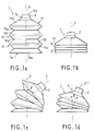
- the device of the invention as shown in Figures 1a to 1d is intended for the transfer of fluids and in particular liquids.
- a sleeve 1 provided with an upstream end 1a for supplying fluid and with an end 1b for discharging said fluid.
- the upstream end 1a has a supply orifice 10a while the downstream end 1b has a distribution orifice 10b, formed here at the outlet of a neck 2, produced in one piece with the sleeve 1 or as an attachment.
- the sleeve 1 can be oriented in all directions from the unfolded position in FIG. 1a to take the positions shown in FIGS. 1b, 1c or 1d.
- the sleeve 1 is here formed, in the manner of a bellows, of a succession of three articulated segments 11, 12, 13.
- the segments 11, 12, 13 each consist of an upstream wall 11a, 12a, 13a, elastically deformable and of a downstream wall 11b, 12b, 13b, rigid.
- the upstream wall 11a, 12a, 13a is capable of retracting completely (Figure 1b) or partially ( Figures 1c and 1d) under the downstream wall 11b, 12b, 13b.
- the retraction of the upstream wall is accompanied by a click and allows the compression of the sleeve 1, along the axis X (FIG. 1b), its bending to bring the neck 2, along the axis Y making an angle ⁇ with the X axis ( Figure 1c) or any combination of compression along X and bending to bring the neck 2 along the Y 'axis, making an angle ⁇ with the X axis ( Figure 1d). All the positions obtained by these deformations are stable, remanent and reversible.
- FIG. 2a shows a partial sectional view of the sleeve 1 in extension, in the position of Figure 1a.
- the upstream walls 11a, 12a and downstream 11b, 12b of the segments 11,12 are inclined towards the inside of the sleeve 1, in the direction of the axis X and are connected to the widest diameter by a toric arch 10 of axis X .
- the diameter of the yoke, and therefore that of the segments is variable along the axis of revolution X, for example by decreasing from the upstream end 1a towards the downstream end 1b, like a funnel.
- the inclination ⁇ between the upstream and downstream walls of each segment 11, 12 is determined as a function, in particular of the dimensions of the sleeve, of the thickness of its wall in particular and of the nature of the material used for its production.
- the sleeve is made with a polymeric plastic material such as a polyolefin.
- This inclination ⁇ is generally between 30 ° and 90 °, when the sleeve 1 is in the unfolded position of FIG. 1a.
- the toric arch 10 is tangent to the downstream wall 11b, 12b to stiffen it.
- the arch 10 describes a quarter of the meridian m upstream, before connecting to the upstream wall 11a, 12a by defining thus a peripheral inflection line i which forms a first articulation for said wall.
- the segments 11, 12, 13 are separated by peripheral grooves g which facilitate the retraction of the upstream wall 11a, 12a and increase the freedom in bending of the sleeve 1.
- the grooves g have, here, a U-shaped section but they can, according to a variant not shown, have a V-shaped section.
- Figure 2b shows a partial sectional view of the sleeve 1 of Figure 2a in the position of Figure 1c.
- the sleeve 1 is bent so as to orient the neck 2 along the axis Y making an angle ⁇ with the axis X of revolution.
- the upper surface of the sleeve 1 is then extended while its lower surface is compressed.
- the upstream walls 11a, 12a, 13a undergo both an elastic deformation and a pivoting downstream on a part of their periphery.
- This pivoting takes place, on the one hand, around the axis of the first articulation which is tangent to the line of inflection i and, on the other hand, around an axis tangent to the downstream edge of the peripheral grooves g , which thus forms a second joint.
- the upstream walls extend substantially parallel to the corresponding downstream walls 11b, 12b, 13b which have not undergone any deformation or pivoting.
- the change in geometry, from the sleeve 1 from the unfolded position (FIG. 2a) to the folded position (FIG. 2b), is therefore carried out by means of a combination between a deformation and a double pivoting of the upstream walls and passing through a unstable transient state of maximum stress causing a click.
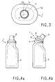
- FIG. 3 represents the sleeve 1 in top view with its downstream end 1b visible.
- the generatrices of the sleeve 1 define a cylinder of revolution of axis X.
- the section of this cylinder consists, here, of two semicircles joined by tangent straight sections.
- the outer surface or envelope of the sleeve 1 is obtained, by making drag a complex line located in one plane and called generator, onto a closed line, located in another plane, called director.
- the contact point is fixed on the generator.
- the plane of the director and the plane of the generator are perpendicular and the plane of the generator constantly contains the normal to the director at the contact point.
- the normal to the plane of the director, at the center of it, is the X axis of the sleeve. If the director has no geometric center, the axis of the sleeve is only defined in direction.
- the downstream wall 13b of the segment is extended at the downstream end 1b by a threaded neck 2, delimiting a discharge orifice 10b.
- the upstream and downstream walls are frustoconical to form substantially annular segments of axis X.
- the section of the sleeve 1 is circular.
- Figures 4a and 4b show side views of a particular application of the transfer device of the invention.
- the sleeve 1 is mounted on the upper part of a container R.
- the sleeve 1 can be made in one piece with the container R or fixed by screwing on the upper part of said container around a discharge orifice.
- the sleeve 1 is, moreover, provided with a neck 2 equipped with a thread onto which a plug 3 is screwed.
Landscapes
- Engineering & Computer Science (AREA)
- Mechanical Engineering (AREA)
- Ceramic Engineering (AREA)
- Containers And Packaging Bodies Having A Special Means To Remove Contents (AREA)
Abstract
caractérisé en ce que ledit manchon (1) est orientable dans toutes les directions et de façon stable, rémanente et réversible, en étant formé d'une succession de segments articulés (11, 12, 13, ...), constitués, d'une paroi aval rigide (11b, 12b, 13b, ...) et d'une paroi amont (11a, 12a, 13a, ...) élastiquement déformable, susceptible de s'escamoter, au moins partiellement, sous ladite paroi aval pour permettre par déclic, la compression et/ou la flexion dudit manchon (1).
Description
- La présente invention concerne un dispositif de transfert de fluides.
- Il existe déjà des dispositifs de transfert comprenant notamment un manchon pourvu d'une extrémité amont d'alimentation et d'une extrémité aval d'évacuation éventuellement obturée par un bouchon.
- De tels dispositifs sont généralement utilisés sur des récipients de produits liquides visqueux. Dans cette utilisation, l'extrémité amont du manchon communique, en partie basse, avec le récipient sur lequel il est fixé, tandis que son extrémité aval supérieure débouche à l'extérieur selon une direction inclinée par rapport à l'axe dudit récipient.
- Cependant dans de tels dispositifs, l'inclinaison ou la courbure du manchon est fixée dès sa fabrication. Dans certains cas, il est prévu une liberté de rotation du manchon selon son axe de révolution, ce qui permet de modifier légèrement l'orientation de l'extrémité aval d'évacuation.
- Toutefois, les possibilités de réglage sont limitées et restent insuffisantes, en particulier pour des applications où il est nécessaire de donner au manchon des géométries complexes en vue d'amener le produit dans des zones difficilement accessibles.
- En outre, les dispositifs traditionnels sont encombrants, du fait même que le manchon fait saillie au-delà de la partie haute du récipient.
- La présente invention a pour but de résoudre les problèmes techniques précédents ou du moins de les atténuer.
- Ce but est atteint, selon l'invention, au moyen d'un dispositif de transfert de fluides comprenant un manchon pourvu d'une extrémité amont d'alimentation et d'une extrémité aval d'évacuation, éventuellement obturée par un bouchon, caractérisé en ce que ledit manchon est orientable dans toutes les directions et de façon stable, rémanente et réversible, en étant formé d'une succession de segments articulés, constitués d'une paroi aval rigide et d'une paroi amont élastiquement déformable, susceptible de s'escamoter, au moins partiellement, sous ladite paroi aval pour permettre, par déclic, la compression et/ou la flexion dudit manchon.
- Selon une caractéristique avantageuse, les parois amont et aval sont inclinées vers l'intérieur du manchon et se raccordent au diamètre le plus large par une arcade.
- De préférence, l'inclinaison entre les parois amont et aval est, à l'état déplié, comprise entre 30° et 90°.
- Ladite arcade est tangente à la paroi aval pour la rigidifier et elle décrit un quart de méridien avant de se raccorder à la paroi amont, en formant ainsi une première articulation pour ladite paroi.
- Selon une autre caractéristique, lesdits segments sont séparés par une gorge périphérique dont le bord aval forme une seconde articulation pour la paroi amont.
- De manière générale, les génératrices du manchon définissent un cylindre éventuellement de révolution.
- Selon un mode de réalisation particulier, les parois amont et aval des segments sont tronconiques et se raccordent par une arcade torique de façon à définir des segments sensiblement annulaires.
- Selon un autre mode de réalisation, le manchon a une section constituée de deux demi-cercles réunis par des tronçons de droite tangents.
- Selon une variante, l'extrémité aval du manchon comporte un filetage pour le vissage d'un bouchon.
- Selon une autre variante, le diamètre des segments, c'est-à-dire, le cas échéant, celui de la surface de raccord en arcade, est variable de l'extrémité amont à l'extrémité aval du manchon.
- Un autre objet de l'invention est une utilisation du dispositif précédent par intégration dans un conditionnement pour assurer l'évacuation dudit produit à partir d'un récipient de produit liquide.
- Le dispositif de l'invention permet d'orienter l'extrémité aval par rapport à l'extrémité amont du manchon selon des géométries complexes, stables, rémanentes et réversibles.
- Il peut être utilisé comme accessoire d'un récipient ou comme outil indépendant et peut même servir d'élément de raccordement entre deux tronçons de conduite de fluide.
- La compression du manchon permet de réduire l'encombrement global du conditionnement, ce qui présente des avantages sur le plan écologique pour des emballages jetables. Par ailleurs, la flexion du manchon procure à la fois une souplesse et une grande facilité d'utilisation.
- A l'état replié, le manchon n'occupe donc que très peu de place, ce qui présente, en outre, des avantages sur les plans économique et esthétique. Dans ces conditions, il peut s'intégrer facilement à un conditionnement de produit, en étant équipé d'un bouchon ou bien encapuchonné à l'intérieur d'un couvercle.
- Ce dispositif trouve, en particulier, son application dans le domaine des produits d'entretien ou de bricolage, des lubrifiants, des médicaments, des cosmétiques ... .
- L'invention sera mieux comprise à la lecture de la description qui va suivre, accompagnée des dessins sur lesquels :
- les figures 1a, 1b, 1c et 1d représentent des vues de profil d'un premier mode de réalisation du dispositif de l'invention dans différentes positions;
- la figure 2a représente une vue partielle en coupe du mode de réalisation des figures 1a à 1d dans la position de la figure 1a;
- la figure 2b représente une vue partielle en coupe du mode de réalisation des figures 1a à 1d dans la position de la figure 1c;
- la figure 3 représente une vue de dessus du mode de réalisation des figures 1a à 1d dans la position de la figure 1a ou 1b.
- les figures 4a et 4b représentent des vues de profil d'une application du mode de réalisation des figures 1a à 1d, respectivement
- Le dispositif de l'invention tel que représenté sur les figures 1a à 1d est destiné au transfert de fluides et en particulier de liquides.
- A cet effet, il comprend un manchon 1 pourvu d'une extrémité amont 1a d'alimentation en fluide et d'une extrémité 1b d'évacuation dudit fluide.
- De préférence, l'extrémité amont 1a possède un orifice d'alimentation 10a tandis que l'extrémité aval 1b possède un orifice de distribution 10b, ménagé ici au débouché d'un col 2, réalisé d'une seule pièce avec le manchon 1 ou sous forme d'une pièce rapportee.
- Selon l'invention, le manchon 1 est orientable dans toutes les directions à partir de la position dépliée de la figure 1a pour prendre les positions représentées sur les figures 1b, 1c ou 1d.
- Le manchon 1 est ici formé, à la manière d'un soufflet, d'une succession de trois segments 11, 12, 13 articulés.
- Les segments 11, 12, 13 sont constitués chacun d'une paroi amont 11a, 12a, 13a, élastiquement déformable et d'une paroi aval 11b, 12b, 13b, rigide. Le paroi amont 11a, 12a, 13a est susceptible de s'escamoter complètement (figure 1b) ou partiellement (figures 1c et 1d) sous la paroi aval 11b, 12b, 13b.
- L'escamotage de la paroi amont s'accompagne d'un déclic et permet la compression du manchon 1, selon l'axe X (figure 1b), sa flexion pour amener le col 2, selon l'axe Y faisant un angle β avec l'axe X (figure 1c) ou toute combinaison entre une compression selon X et une flexion pour amener le col 2, selon l'axe Y', faisant un angle θ avec l'axe X (figure 1d). Toutes les positions obtenues par ces déformations sont stables, rémanentes et réversibles.
- La figure 2a représente une vue partielle en coupe du manchon 1 en extension, dans la position de la figure 1a.
- Les parois amont 11a, 12a et aval 11b, 12b des segments 11,12 sont inclinées vers l'intérieur du manchon 1, en direction de l'axe X et se raccordent au diamètre le plus large par une arcade torique 10 d'axe X.
- Dans un autre mode de réalisation, non représenté, le diamètre de l'arcade, et donc celui des segments, est variable le long de l'axe de révolution X, par exemple en diminuant de l'extrémité amont 1a vers l'extrémité aval 1b, à la manière d'un entonnoir.
- L'inclinaison α entre les parois amont et aval de chaque segment 11, 12 est déterminée en fonction, notamment des dimensions du manchon, de l'épaisseur de sa paroi en particulier et de la nature du matériau utilisé pour sa réalisation. De préférence, le manchon est réalisé avec une matière plastique polymère telle qu'une polyoléfine.
- Cette inclinaison α est généralement comprise entre 30° et 90°, lorsque le manchon 1 est dans la position dépliée de la figure 1a.
- L'arcade torique 10 est tangente à la paroi aval 11b, 12b pour la rigidifier.
- En revanche, l'arcade 10 décrit un quart de méridien m vers l'amont, avant de se raccorder à la paroi amont 11a, 12a en définissant ainsi une ligne d'inflexion périphérique i qui forme une première articulation pour ladite paroi.
- Les segments 11, 12, 13 sont séparés par des gorges périphériques g qui facilitent l'escamotage de la paroi amont 11a, 12a et augmentent la liberté en flexion du manchon 1.
- Les gorges g ont, ici, une section en U mais elles peuvent, selon une variante non représentée, avoir une section en V.
- La figure 2b représente une vue partielle en coupe du manchon 1 de la figure 2a dans la position de la figure 1c.
- Dans cette position, le manchon 1 est fléchi de façon à orienter le col 2 selon l'axe Y faisant un angle β avec l'axe X de révolution.
- L'extrados du manchon 1 est alors en extension tandis que son intrados est comprimé.
- La flexion maximum est obtenue quand toutes les parois amont 11a, 12a, 13a des segments sont escamotées sur l'intrados du manchon 1.
- Au cours de la phase d'escamotage, les parois amont 11a, 12a, 13a, subissent à la fois une déformation élastique et un pivotement vers l'aval sur une partie de leur pourtour. Ce pivotement s'effectue, d'une part, autour de l'axe de la première articulation qui est tangent à la ligne d'inflexion i et, d'autre part, autour d'un axe tangent au bord aval des gorges périphériques g, qui forme ainsi une seconde articulation.
- En fin d'escamotage, les parois amont s'étendent de façon sensiblement parallèle aux parois aval 11b, 12b, 13b correspondantes qui n'ont subi aucune déformation, ni pivotement.
- Le changement de géométrie, du manchon 1 de la position dépliée (figure 2a) à la position repliée (figure 2b), s'effectue donc au moyen d'une combinaison entre une déformation et un double pivotement des parois amont et en passant par un état transitoire instable de contraintes maximum qui provoque un déclic.
- La figure 3 représente le manchon 1 en vue de dessus avec son extrémité aval 1b apparente. Dans ce mode de réalisation, les génératrices du manchon 1 définissent un cylindre de révolution d'axe X. La section de ce cylindre est constituée, ici, de deux demi-cercles réunis par des tronçons de droite tangents. De manière générale la surface extérieure ou enveloppe du manchon 1 est obtenue, en faisant glisser une ligne complexe située dans un plan et appelée génératrice, sur une ligne fermée, située dans un autre plan, et appelée directrice. Le point de contact est fixe sur la génératrice. Le plan de la directrice et le plan de la génératrice sont perpendiculaires et le plan de la génératrice contient constamment la normale à la directrice au point contact. La normale au plan de la directrice, au centre de celle-ci, est l'axe X du manchon. Si la directrice n'a pas de centre géométrique, l'axe du manchon n'est défini qu'en direction.
- La paroi aval 13b du segment se prolonge à l'extrémité aval 1b par un col 2 fileté, délimitant un orifice d'évacuation 10b.
- Selon un autre mode de réalisation, non représenté, les parois amont et aval sont tronconiques pour former des segments sensiblement annulaires d'axe X. Dans ce cas, la section du manchon 1 est circulaire.
- Les figures 4a et 4b représentent des vues de profil d'une application particulière du dispositif de transfert de l'invention.
- Dans cette application, le manchon 1 est monté sur la partie haute d'un récipient R.
- Le manchon 1 peut être réalisé d'une seule pièce avec le récipient R ou fixé par vissage sur la partie haute dudit récipient autour d'un orifice d'évacuation.
- Le manchon 1 est, en outre, pourvu d'un col 2 équipé d'un filetage sur lequel vient se visser un bouchon 3.
Claims (10)
- Dispositif de transfert de fluides comprenant un manchon (1) pourvu d'une extrémité amont (1a) d'alimentation et d'une extrémité aval (1b) d'évacuation éventuellement obturée par un bouchon (3),
ledit manchon (1) étant orientable dans toutes les directions et de façon stable, rémanente et réversible, en étant formé d'une succession de segments articulés (11, 12, 13, ...), constitués, d'une paroi aval rigide (11b, 12b, 13b, ...) et d'une paroi amont (11a, 12a, 13a, ...) élastiquement déformable, susceptible de s'escamoter, au moins partiellement, sous ladite paroi aval pour permettre la compression, l'extension et/ou la flexion dudit manchon (1),
caractérisé en ce que les parois amont (11a, 12a, ...) et aval (11b, 12b, ...) sont inclinées vers l'intérieur du manchon (1) et se raccordent au diamètre le plus large par une arcade (10) décrivant un quart de méridien (m) avant de se raccorder à la paroi amont (11a, 12a, ...) en définissant ainsi une ligne d'inflexion (i) qui forme une première articulation pour ladite paroi. - Dispositif selon la revendication 1, caractérisé en ce que l'inclinaison (α) entre les parois amont et aval est, à l'état déplié, comprise entre 30° et 90°.
- Dispositif selon la revendication 1 ou 2, caractérisé en ce que ladite arcade (10) est tangente à la paroi aval (11b, 12b, ...) pour la rigidifier.
- Dispositif selon l'une des revendications précédentes, caractérisé en ce que lesdits segments (11, 12, 13) sont séparés par une gorge périphérique (g) dont le bord aval forme une seconde articulation pour la paroi amont (11a, 12a ...).
- Dispositif selon l'une des revendications précédentes, caractérisé en ce que les génératrices du manchon (1) définissent un cylindre éventuellement de révolution.
- Dispositif selon l'une des revendications précédentes, caractérisé en ce que les parois amont (11a, 12a, 13a, ...) et aval (11b, 12b, 13b, ...) des segments (11, 12, 13) sont tronconiques et se raccordent par une arcade (10) torique de façon à définir des segments sensiblement annulaires.
- Dispositif selon l'une des revendications précédentes, caractérisé en ce que ledit manchon (1) a une section constituée de deux demi-cercles réunis par des tronçons de droite tangents.
- Dispositif selon l'une des revendications précédentes, caractérisé en ce que l'extrémité aval (1b) du manchon (1) comporte un filetage pour le vissage d'un bouchon (3).
- Dispositif selon l'une des revendications précédentes, caractérisé en ce que le diamètre des segments (11, 12, 13) est variable de l'extrémité amont (1a) à l'extrémité aval (1b).
- Utilisation du dispositif, selon l'une des revendications précédentes, par intégration dans un conditionnement de produit liquide pour assurer l'évacuation dudit produit à partir d'un récipient (R).
Priority Applications (1)
| Application Number | Priority Date | Filing Date | Title |
|---|---|---|---|
| EP96400788A EP0801002A1 (fr) | 1996-04-12 | 1996-04-12 | Dispositif de transfert de fluides |
Applications Claiming Priority (1)
| Application Number | Priority Date | Filing Date | Title |
|---|---|---|---|
| EP96400788A EP0801002A1 (fr) | 1996-04-12 | 1996-04-12 | Dispositif de transfert de fluides |
Publications (1)
| Publication Number | Publication Date |
|---|---|
| EP0801002A1 true EP0801002A1 (fr) | 1997-10-15 |
Family
ID=8225244
Family Applications (1)
| Application Number | Title | Priority Date | Filing Date |
|---|---|---|---|
| EP96400788A Withdrawn EP0801002A1 (fr) | 1996-04-12 | 1996-04-12 | Dispositif de transfert de fluides |
Country Status (1)
| Country | Link |
|---|---|
| EP (1) | EP0801002A1 (fr) |
Cited By (26)
| Publication number | Priority date | Publication date | Assignee | Title |
|---|---|---|---|---|
| WO2000044630A1 (fr) * | 1999-01-27 | 2000-08-03 | Pedulla Christian Pio | Bouteille jetable a parois laterales pouvant s'affaisser graduellement sans pouvoir recuperer leur forme premiere |
| WO2006027084A1 (fr) * | 2004-09-07 | 2006-03-16 | Sata Farbspritztechnik Gmbh & Co. Kg | Reservoir d'ecoulement pour pistolet a peinture |
| WO2008017823A1 (fr) * | 2006-08-05 | 2008-02-14 | Concentrated Solutions Limited | Contenant |
| US8925836B2 (en) | 2008-10-29 | 2015-01-06 | Sata Gmbh & Co. Kg | Gravity cup for a paint sprayer |
| USD740393S1 (en) | 2013-09-27 | 2015-10-06 | Sata Gmbh & Co. Kg | Paint spray gun |
| US9327301B2 (en) | 2008-03-12 | 2016-05-03 | Jeffrey D. Fox | Disposable spray gun cartridge |
| USD758537S1 (en) | 2014-07-31 | 2016-06-07 | Sata Gmbh & Co. Kg | Paint spray gun rear portion |
| US9409197B2 (en) | 2013-12-18 | 2016-08-09 | Sata Gmbh & Co. Kg | Air nozzle closure for a spray gun |
| USD768820S1 (en) | 2014-09-03 | 2016-10-11 | Sata Gmbh & Co. Kg | Paint spray gun with pattern |
| USD770593S1 (en) | 2014-07-31 | 2016-11-01 | Sata Gmbh & Co. Kg | Paint spray gun |
| US9533317B2 (en) | 2009-07-08 | 2017-01-03 | Sata Gmbh & Co. Kg | Paint spray gun |
| US9782785B2 (en) | 2010-12-02 | 2017-10-10 | Sata Gmbh & Co. Kg | Spray gun and accessories |
| US9782784B2 (en) | 2010-05-28 | 2017-10-10 | Sata Gmbh & Co. Kg | Nozzle head for a spray device |
| US9878336B2 (en) | 2006-12-05 | 2018-01-30 | Sata Gmbh & Co. Kg | Fluid reservoir for a paint spray gun |
| US10189037B2 (en) | 2011-06-30 | 2019-01-29 | Sata Gmbh & Co. Kg | Easy-to-clean spray gun, accessories therefor, and mounting and dismounting methods |
| US10464076B2 (en) | 2015-12-21 | 2019-11-05 | Sata Gmbh & Co. Kg | Air cap and nozzle assembly for a spray gun, and spray gun |
| US10471449B2 (en) | 2016-08-19 | 2019-11-12 | Sata Gmbh & Co. Kg | Air cap arrangement and spray gun |
| US10702879B2 (en) | 2014-07-31 | 2020-07-07 | Sata Gmbh & Co. Kg | Spray gun manufacturing method, spray gun, spray gun body and cover |
| US10835911B2 (en) | 2016-08-19 | 2020-11-17 | Sata Gmbh & Co. Kg | Trigger for a spray gun and spray gun having same |
| US11141747B2 (en) | 2015-05-22 | 2021-10-12 | Sata Gmbh & Co. Kg | Nozzle arrangement for a spray gun |
| US11801521B2 (en) | 2018-08-01 | 2023-10-31 | Sata Gmbh & Co. Kg | Main body for a spray gun, spray guns, spray gun set, method for producing a main body for a spray gun and method for converting a spray gun |
| US11826771B2 (en) | 2018-08-01 | 2023-11-28 | Sata Gmbh & Co. Kg | Set of nozzles for a spray gun, spray gun system, method for embodying a nozzle module, method for selecting a nozzle module from a set of nozzles for a paint job, selection system and computer program product |
| US11865558B2 (en) | 2018-08-01 | 2024-01-09 | Sata Gmbh & Co. Kg | Nozzle for a spray gun, nozzle set for a spray gun, spray guns and methods for producing a nozzle for a spray gun |
| US12097519B2 (en) | 2020-09-11 | 2024-09-24 | Sata Gmbh & Co. Kg | Sealing element for sealing a transition between a spray gun body and an attachment of a spray gun, attachment, in particular a paint nozzle arrangement for a spray gun and a spray gun, in particular a paint spray gun |
| US12515230B2 (en) | 2018-09-10 | 2026-01-06 | Sata Gmbh & Co. Kg | Paint gun, material application system, and method for operating same |
| US12594566B2 (en) | 2020-03-06 | 2026-04-07 | Sata Gmbh & Co. Kg | Spray gun, in particular a pressurized air atomization paint spray gun, in particular a hand-held pressurized air atomization paint spray gun |
Citations (3)
| Publication number | Priority date | Publication date | Assignee | Title |
|---|---|---|---|---|
| US4602728A (en) * | 1985-03-15 | 1986-07-29 | Ha Sung M | Container |
| US4921147A (en) * | 1989-02-06 | 1990-05-01 | Michel Poirier | Pouring spout |
| US5133481A (en) * | 1991-01-25 | 1992-07-28 | Mayfield Todd A | Bottle with collapsible spout |
-
1996
- 1996-04-12 EP EP96400788A patent/EP0801002A1/fr not_active Withdrawn
Patent Citations (3)
| Publication number | Priority date | Publication date | Assignee | Title |
|---|---|---|---|---|
| US4602728A (en) * | 1985-03-15 | 1986-07-29 | Ha Sung M | Container |
| US4921147A (en) * | 1989-02-06 | 1990-05-01 | Michel Poirier | Pouring spout |
| US5133481A (en) * | 1991-01-25 | 1992-07-28 | Mayfield Todd A | Bottle with collapsible spout |
Cited By (34)
| Publication number | Priority date | Publication date | Assignee | Title |
|---|---|---|---|---|
| WO2000044630A1 (fr) * | 1999-01-27 | 2000-08-03 | Pedulla Christian Pio | Bouteille jetable a parois laterales pouvant s'affaisser graduellement sans pouvoir recuperer leur forme premiere |
| US6598755B1 (en) | 1999-01-27 | 2003-07-29 | Pedulla Christian Pio | Disposable bottle having a gradually collapsible, recovery-free, structure of its side-walls |
| AU777340B2 (en) * | 1999-01-27 | 2004-10-14 | Gianfilippo Pagliacci | Disposable bottle having a gradually collapsible, recovery-free, structure of its sidewalls |
| WO2006027084A1 (fr) * | 2004-09-07 | 2006-03-16 | Sata Farbspritztechnik Gmbh & Co. Kg | Reservoir d'ecoulement pour pistolet a peinture |
| US8052071B2 (en) | 2004-09-07 | 2011-11-08 | Sata Gmbh & Co. Kg | Fluid reservoir for a paint spray gun |
| CN102921576A (zh) * | 2004-09-07 | 2013-02-13 | 萨塔有限两合公司 | 用于喷漆枪的流体储存器 |
| DE102004043599B4 (de) * | 2004-09-07 | 2014-11-27 | Sata Gmbh & Co. Kg | Fließbecher für eine Farbspritzpistole |
| CN102921576B (zh) * | 2004-09-07 | 2015-11-18 | 萨塔有限两合公司 | 用于喷漆枪的流体储存器 |
| WO2008017823A1 (fr) * | 2006-08-05 | 2008-02-14 | Concentrated Solutions Limited | Contenant |
| US9878336B2 (en) | 2006-12-05 | 2018-01-30 | Sata Gmbh & Co. Kg | Fluid reservoir for a paint spray gun |
| US9327301B2 (en) | 2008-03-12 | 2016-05-03 | Jeffrey D. Fox | Disposable spray gun cartridge |
| US8925836B2 (en) | 2008-10-29 | 2015-01-06 | Sata Gmbh & Co. Kg | Gravity cup for a paint sprayer |
| US9533317B2 (en) | 2009-07-08 | 2017-01-03 | Sata Gmbh & Co. Kg | Paint spray gun |
| US9782784B2 (en) | 2010-05-28 | 2017-10-10 | Sata Gmbh & Co. Kg | Nozzle head for a spray device |
| US9782785B2 (en) | 2010-12-02 | 2017-10-10 | Sata Gmbh & Co. Kg | Spray gun and accessories |
| US10189037B2 (en) | 2011-06-30 | 2019-01-29 | Sata Gmbh & Co. Kg | Easy-to-clean spray gun, accessories therefor, and mounting and dismounting methods |
| USD740393S1 (en) | 2013-09-27 | 2015-10-06 | Sata Gmbh & Co. Kg | Paint spray gun |
| US9409197B2 (en) | 2013-12-18 | 2016-08-09 | Sata Gmbh & Co. Kg | Air nozzle closure for a spray gun |
| US10702879B2 (en) | 2014-07-31 | 2020-07-07 | Sata Gmbh & Co. Kg | Spray gun manufacturing method, spray gun, spray gun body and cover |
| USD770593S1 (en) | 2014-07-31 | 2016-11-01 | Sata Gmbh & Co. Kg | Paint spray gun |
| USD758537S1 (en) | 2014-07-31 | 2016-06-07 | Sata Gmbh & Co. Kg | Paint spray gun rear portion |
| USD798419S1 (en) | 2014-07-31 | 2017-09-26 | Sata Gmbh & Co. Kg | Paint spray gun |
| USD835235S1 (en) | 2014-07-31 | 2018-12-04 | Sata Gmbh & Co. Kg | Paint spray gun |
| USD768820S1 (en) | 2014-09-03 | 2016-10-11 | Sata Gmbh & Co. Kg | Paint spray gun with pattern |
| US11141747B2 (en) | 2015-05-22 | 2021-10-12 | Sata Gmbh & Co. Kg | Nozzle arrangement for a spray gun |
| US10464076B2 (en) | 2015-12-21 | 2019-11-05 | Sata Gmbh & Co. Kg | Air cap and nozzle assembly for a spray gun, and spray gun |
| US10835911B2 (en) | 2016-08-19 | 2020-11-17 | Sata Gmbh & Co. Kg | Trigger for a spray gun and spray gun having same |
| US10471449B2 (en) | 2016-08-19 | 2019-11-12 | Sata Gmbh & Co. Kg | Air cap arrangement and spray gun |
| US11801521B2 (en) | 2018-08-01 | 2023-10-31 | Sata Gmbh & Co. Kg | Main body for a spray gun, spray guns, spray gun set, method for producing a main body for a spray gun and method for converting a spray gun |
| US11826771B2 (en) | 2018-08-01 | 2023-11-28 | Sata Gmbh & Co. Kg | Set of nozzles for a spray gun, spray gun system, method for embodying a nozzle module, method for selecting a nozzle module from a set of nozzles for a paint job, selection system and computer program product |
| US11865558B2 (en) | 2018-08-01 | 2024-01-09 | Sata Gmbh & Co. Kg | Nozzle for a spray gun, nozzle set for a spray gun, spray guns and methods for producing a nozzle for a spray gun |
| US12515230B2 (en) | 2018-09-10 | 2026-01-06 | Sata Gmbh & Co. Kg | Paint gun, material application system, and method for operating same |
| US12594566B2 (en) | 2020-03-06 | 2026-04-07 | Sata Gmbh & Co. Kg | Spray gun, in particular a pressurized air atomization paint spray gun, in particular a hand-held pressurized air atomization paint spray gun |
| US12097519B2 (en) | 2020-09-11 | 2024-09-24 | Sata Gmbh & Co. Kg | Sealing element for sealing a transition between a spray gun body and an attachment of a spray gun, attachment, in particular a paint nozzle arrangement for a spray gun and a spray gun, in particular a paint spray gun |
Similar Documents
| Publication | Publication Date | Title |
|---|---|---|
| EP0801002A1 (fr) | Dispositif de transfert de fluides | |
| CA2040082C (fr) | Ensemble de distribution d'au moins un produit liquide ou sous forme de creme | |
| CA2019406C (fr) | Garniture d'etancheite a talon annulaire d'ancrage | |
| EP0538094B1 (fr) | Récipient métallique à ouverture partielle par rupture d'une ligne de moindre résistance | |
| EP0250343A1 (fr) | Bouchon à vis étanche pour col fileté de récipient | |
| WO1999062776A1 (fr) | Fermeture ayant moyens de perforation et embout verseur | |
| FR2729924A1 (fr) | Flacon de distribution de produit | |
| EP0269499A1 (fr) | Dispositif à bec verseur escamotable et extensible | |
| EP0850851B1 (fr) | Valve pour la distribution de fluides sous pression | |
| EP2135682B2 (fr) | Flacon de distribution d'un produit fluide comprenant un manchon de maintien de la pompe de distribution déformable et dévissable | |
| LU88845A1 (fr) | Conditionnement pour produits liquides et en particulier pour produits alimentaires | |
| CA2097598C (fr) | Procede pour assurer le positionnement angulaire d'un dispositif de bouchage orientable par rapport a un tube souple de distribution comportant un marquage | |
| FR3035647B1 (fr) | Dispositif de fermeture d'un recipient par vissage, securise par un ergot escamotable. | |
| EP2178415A2 (fr) | Dispositif de produit cosmetique comprenant un reservoir et un applicateur | |
| EP1181219A1 (fr) | Embout pour la distribution et la pulverisation de produits pharmaceutiques liquides | |
| EP1391393B1 (fr) | Dispositif de distribution | |
| LU88851A1 (fr) | Capsule pour le bouchage d'un récipient dont le col est équipé d'une collerette | |
| EP0092473A1 (fr) | Dispositif de distribution en proportion réglable de deux substances pâteuses | |
| EP0739826B1 (fr) | Dispositif de fermeture pour une ouverture latérale de distribution escamotable axialement | |
| EP2596268B1 (fr) | Soufflet de direction se presentant sous forme d'un manchon | |
| BE897445A (fr) | Flacon equipe d'un capot de bouchage etanche | |
| EP1476365A1 (fr) | Dispositif d assemblage entre deux elements tubulaires et el ements tubulaires permettant sa mise en oeuvre | |
| FR3073373B1 (fr) | Tete d'application et de distribution de produit cosmetique, et dispositif de conditionnement associe | |
| EP0648683A1 (fr) | Dispositif de bouchage d'un récipient muni d'un goulot, du type flacon ou pot | |
| EP1433712A1 (fr) | Bouchon distributeur à débit variable |
Legal Events
| Date | Code | Title | Description |
|---|---|---|---|
| PUAI | Public reference made under article 153(3) epc to a published international application that has entered the european phase |
Free format text: ORIGINAL CODE: 0009012 |
|
| AK | Designated contracting states |
Kind code of ref document: A1 Designated state(s): BE CH DE ES FR GB IT LI LU MC NL |
|
| RBV | Designated contracting states (corrected) |
Designated state(s): BE CH DE ES FR GB IT LI LU MC NL |
|
| 17P | Request for examination filed |
Effective date: 19980407 |
|
| 17Q | First examination report despatched |
Effective date: 19980608 |
|
| GRAG | Despatch of communication of intention to grant |
Free format text: ORIGINAL CODE: EPIDOS AGRA |
|
| GRAG | Despatch of communication of intention to grant |
Free format text: ORIGINAL CODE: EPIDOS AGRA |
|
| GRAH | Despatch of communication of intention to grant a patent |
Free format text: ORIGINAL CODE: EPIDOS IGRA |
|
| RAP1 | Party data changed (applicant data changed or rights of an application transferred) |
Owner name: AGRIPLAS BENELUX |
|
| STAA | Information on the status of an ep patent application or granted ep patent |
Free format text: STATUS: THE APPLICATION IS DEEMED TO BE WITHDRAWN |
|
| 18D | Application deemed to be withdrawn |
Effective date: 19991201 |