EP0801187A1 - Fugenabdeckung für Oberflächenbeschichtung - Google Patents
Fugenabdeckung für Oberflächenbeschichtung Download PDFInfo
- Publication number
- EP0801187A1 EP0801187A1 EP97201002A EP97201002A EP0801187A1 EP 0801187 A1 EP0801187 A1 EP 0801187A1 EP 97201002 A EP97201002 A EP 97201002A EP 97201002 A EP97201002 A EP 97201002A EP 0801187 A1 EP0801187 A1 EP 0801187A1
- Authority
- EP
- European Patent Office
- Prior art keywords
- head
- joint
- profile
- longitudinal
- ball joint
- Prior art date
- Legal status (The legal status is an assumption and is not a legal conclusion. Google has not performed a legal analysis and makes no representation as to the accuracy of the status listed.)
- Granted
Links
- 238000000576 coating method Methods 0.000 claims description 4
- 239000011248 coating agent Substances 0.000 claims description 3
- 238000003780 insertion Methods 0.000 claims description 3
- 230000037431 insertion Effects 0.000 claims description 3
- 238000004873 anchoring Methods 0.000 claims description 2
- 241000309551 Arthraxon hispidus Species 0.000 claims 1
- 210000004417 patella Anatomy 0.000 claims 1
- 208000031968 Cadaver Diseases 0.000 description 5
- 241000587161 Gomphocarpus Species 0.000 description 3
- 239000000853 adhesive Substances 0.000 description 2
- 230000001070 adhesive effect Effects 0.000 description 2
- 230000032683 aging Effects 0.000 description 1
- 230000000994 depressogenic effect Effects 0.000 description 1
- 238000005553 drilling Methods 0.000 description 1
- 238000000034 method Methods 0.000 description 1
- 230000000717 retained effect Effects 0.000 description 1
Images
Classifications
-
- E—FIXED CONSTRUCTIONS
- E04—BUILDING
- E04F—FINISHING WORK ON BUILDINGS, e.g. STAIRS, FLOORS
- E04F19/00—Other details of constructional parts for finishing work on buildings
- E04F19/02—Borders; Finishing strips, e.g. beadings; Light coves
- E04F19/06—Borders; Finishing strips, e.g. beadings; Light coves specially designed for securing panels or masking the edges of wall- or floor-covering elements
- E04F19/065—Finishing profiles with a T-shaped cross-section or the like
- E04F19/066—Finishing profiles with a T-shaped cross-section or the like fixed onto a base profile by means of a separate connector
-
- A—HUMAN NECESSITIES
- A47—FURNITURE; DOMESTIC ARTICLES OR APPLIANCES; COFFEE MILLS; SPICE MILLS; SUCTION CLEANERS IN GENERAL
- A47G—HOUSEHOLD OR TABLE EQUIPMENT
- A47G27/00—Floor fabrics; Fastenings therefor
- A47G27/04—Carpet fasteners; Carpet-expanding devices ; Laying carpeting; Tools therefor
- A47G27/0437—Laying carpeting, e.g. wall-to-wall carpeting
- A47G27/045—Gripper strips; Seaming strips; Edge retainers
-
- E—FIXED CONSTRUCTIONS
- E04—BUILDING
- E04F—FINISHING WORK ON BUILDINGS, e.g. STAIRS, FLOORS
- E04F19/00—Other details of constructional parts for finishing work on buildings
- E04F19/02—Borders; Finishing strips, e.g. beadings; Light coves
- E04F19/06—Borders; Finishing strips, e.g. beadings; Light coves specially designed for securing panels or masking the edges of wall- or floor-covering elements
-
- E—FIXED CONSTRUCTIONS
- E04—BUILDING
- E04F—FINISHING WORK ON BUILDINGS, e.g. STAIRS, FLOORS
- E04F19/00—Other details of constructional parts for finishing work on buildings
- E04F19/02—Borders; Finishing strips, e.g. beadings; Light coves
- E04F19/06—Borders; Finishing strips, e.g. beadings; Light coves specially designed for securing panels or masking the edges of wall- or floor-covering elements
- E04F19/062—Borders; Finishing strips, e.g. beadings; Light coves specially designed for securing panels or masking the edges of wall- or floor-covering elements used between similar elements
- E04F19/063—Borders; Finishing strips, e.g. beadings; Light coves specially designed for securing panels or masking the edges of wall- or floor-covering elements used between similar elements for simultaneously securing panels having different thicknesses
Definitions
- Joint covers have been known for a long time which are intended to mask the passage from one floor covering to another.
- a decorative joint cover is known in particular having an adhesive mass on its underside, this element having to be glued to the ground (BE-A-758356).
- This type of joint cover has the drawback of the aging of the adhesive and of an insufficient anchoring thereby.
- joint covers to be nailed or screwed to the ground.
- An example is a very easy mounting joint cover (BE-A-1007798).
- joint covers formed by two longitudinal sections hinged together and enclosing between them the two coatings whose joint is to be covered (BE-A-859782).
- the lower profit is to stick to the ground and has the same drawbacks as the joint cover mentioned above.
- joint covers formed of a profit provided with two rigid longitudinal ribs defining with the bottom of the profit a slide to allow the introduction, by one end of the slide, of nail heads (EP-A-588734 ).
- the bottom of the profit and the nail head are arranged so as to form a joint between them.
- the profiling of the groove for receiving the nail heads imposes limits on the articulation to the point that the plaintiff is obliged to place on the market several different joint cover profiles according to the height of the unevenness at catch up. This results in huge storage problems.
- the object of the present invention is to solve these problems by developing a joint cover which is easy to assemble and disassemble, and of a single type, that is to say suitable both for covering a joint in absence of unevenness only in the presence of a difference in level of the order of for example 15 to 16 mm, which is generally accepted in this technique as the maximum value to be made up.
- a joint cover of this kind offers the advantage of allowing a very significant inclination of the profile relative to the bodies of the fixing means. These can be placed beforehand in a perfectly adjusted manner. The cover profiles are then fixed by snap-fastening the ball joints of the heads of the fixing means in the body thereof. Placing and adjusting the height of the joint cover is therefore particularly easy.
- the ball has a spherical shape and the ball housing has a circular opening oriented towards the profile, which has a diameter slightly smaller than that of the spherical ball. Freedom of pivoting of the head of the fixing means is thus particularly well ensured.
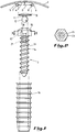
- Figure 1 shows an elevational side view, exploded, of an embodiment according to the invention.
- FIG. 2 represents a sectional view, along line II-II, of FIG. 1.
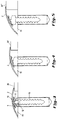
- Figures 3 to 5 show a joint cover according to the invention used to hide three differences in level.
- joint covers according to the invention can be used to mask a joint between surfaces other than floor surfaces, for example wall surfaces.
- a joint cover 1 comprising an elongated profile 2 and fixing means 3.
- the profile 2 has a first surface, which in the illustrated case is the upper surface, and a second surface, here the lower surface 4.
- Two parallel longitudinal ribs 5, 6 protrude downward from this lower surface 4 and flanges 7, 8 extend towards each other from each longitudinal rib 5, 6, forming between them a predetermined width interval D.
- a longitudinal groove 9 is thus defined between the lower surface 4 of the profile, the longitudinal ribs 5, 6 and the flanges 7, 8, and it has an opening downwards along the width interval D. This groove is accessible also by end openings at the longitudinal ends, not shown, of the elongated profile.
- the means 3 for fixing the profile 2 to the ground each comprise a head 10, having a width greater than that of the abovementioned interval. It is housed in the groove 9 of the profile 2 when the profile is in the fixing position (see Figures 3 to 5).
- the shape of the head is advantageously adapted to that of the throat to obtain a soft friction between them, which allows both an easy sliding of the head in the throat, but also its holding in place when one stops sliding it .
- this head 10 is an independent part which can be introduced separately into the longitudinal groove 9 of the profile 2. It is provided with a rod 11 which, at one end, has a ball joint 12, which has, in the illustrated example, the shape of a sphere.
- the fixing means 3 also each comprise a body anchible to the ground.
- the body comprises an anchor rod with an external thread 14 and a hinge head 15 provided with multiple sections, in particular hexagonal. This body can thus be screwed by an appropriate common key, either directly into the ground, or into a dowel 16 previously introduced into a hole drilled in the ground.
- the body comprises, in its articulation head 15, a ball joint housing 17 open towards the outside and in which the ball joint 12 of a head 10 can be pressed in by snap-fastening.
- the housing has a circular opening 18, which in the body fixing position is oriented upwards. The diameter of this opening 18 is slightly smaller than that of the spherical ball joint 12. It follows that after snap-fastening the ball joint 12 is retained in the ball joint housing 17.
- the ball joint 12 of the head 10 and the ball joint housing 17 of the body of the fixing means 3 thus form an articulation allowing a deep inclination of the head, relative to the longitudinal axis of the body.
- the head 10 When the head 10 is inserted into the groove 9 of a joint cover, it pivots in a manner corresponding to the head.
- the joint cover must be placed to mask different inequalities between two floors 19 and 20, 20 'or 20' 'respectively.
- the difference in level between 19 and 20 is 5mm, between 19 and 20 'by 10mm and between 19 and 20' 'by 16mm.
- heads 10 in a number corresponding to the fixing means 3 used, are passed through the groove 9 of the profile 2, through one of its lateral ends.
- the heads are placed in the groove at the height of the fixing means and their ball joint 12 can then be snapped into the corresponding ball joint housing 17 by simple pressure on the joint cover.
- the joint cover automatically takes the appropriate inclination between the two ground levels. If the height of the articulation heads 15 has been incorrectly adjusted, it is still possible to disengage the joint cover, readjust the height of the articulation heads 15 by screwing and then re-engage the joint cover.
- a screwing wrench can be inserted suitable which allows to screw the body of the fastening means, even when it is in the very depressed position, as in Figure 3 for example.
- fixing means to drive in, for example nails, dowels, etc., the head of which comprises the ball joint housing.
- the ball joints have a shape different from a spherical shape, for example a cylindrical shape, and that the ball joints have an appropriate corresponding shape.
Landscapes
- Engineering & Computer Science (AREA)
- Architecture (AREA)
- Civil Engineering (AREA)
- Structural Engineering (AREA)
- Closures For Containers (AREA)
- Pens And Brushes (AREA)
- Pivots And Pivotal Connections (AREA)
- Coating Apparatus (AREA)
- Rehabilitation Tools (AREA)
Applications Claiming Priority (2)
| Application Number | Priority Date | Filing Date | Title |
|---|---|---|---|
| BE9600318 | 1996-04-12 | ||
| BE9600318A BE1010096A3 (fr) | 1996-04-12 | 1996-04-12 | Couvre-joint pour revetement de surface. |
Publications (2)
| Publication Number | Publication Date |
|---|---|
| EP0801187A1 true EP0801187A1 (de) | 1997-10-15 |
| EP0801187B1 EP0801187B1 (de) | 2001-10-24 |
Family
ID=3889670
Family Applications (1)
| Application Number | Title | Priority Date | Filing Date |
|---|---|---|---|
| EP97201002A Expired - Lifetime EP0801187B1 (de) | 1996-04-12 | 1997-04-08 | Fugenabdeckung für Oberflächenbeschichtung |
Country Status (4)
| Country | Link |
|---|---|
| EP (1) | EP0801187B1 (de) |
| AT (1) | ATE207570T1 (de) |
| BE (1) | BE1010096A3 (de) |
| DE (1) | DE69707544T2 (de) |
Cited By (6)
| Publication number | Priority date | Publication date | Assignee | Title |
|---|---|---|---|---|
| WO2000019037A1 (fr) * | 1998-09-30 | 2000-04-06 | Dinac S.A. | Barre de seuil a rattrapage de niveau |
| EP1223268A1 (de) * | 2001-01-11 | 2002-07-17 | Proline Profil System GmbH | Fussbodenleiste |
| WO2003042469A1 (de) | 2001-06-12 | 2003-05-22 | Pavol Matus | Leistensystem zum verbinden von fussböden, insbesondere parkettböden |
| EP1403444A1 (de) * | 2002-09-24 | 2004-03-31 | Manfred Kochler | Profilschienensystem |
| WO2005049938A1 (de) * | 2003-10-24 | 2005-06-02 | Herm. Friedr. Künne Gmbh & Co. | Fussbodenprofilanordnung mit gelenk |
| GB2574407A (en) * | 2018-06-04 | 2019-12-11 | Celtic Heights Ltd | Roof or wall hole closing device |
Families Citing this family (1)
| Publication number | Priority date | Publication date | Assignee | Title |
|---|---|---|---|---|
| DE10211750B4 (de) * | 2002-03-18 | 2007-01-04 | Richard Malcher | Profilsystem |
Citations (4)
| Publication number | Priority date | Publication date | Assignee | Title |
|---|---|---|---|---|
| US2996751A (en) * | 1958-09-09 | 1961-08-22 | Stanley Works | Snap-on molding |
| BE859782A (fr) * | 1976-10-15 | 1978-04-14 | Dinac Sa | Profiles de jonction de revetements |
| EP0588734A1 (de) * | 1992-09-16 | 1994-03-23 | Dinac Profinition S.A. | Leicht montierbare Schwelle |
| BE1007798A6 (fr) * | 1995-06-01 | 1995-10-24 | Vanroy Guillaume Werkhuizen | Couvre-joint pour revetement de sol et procede pour sa mise en oeuvre. |
-
1996
- 1996-04-12 BE BE9600318A patent/BE1010096A3/fr not_active IP Right Cessation
-
1997
- 1997-04-08 EP EP97201002A patent/EP0801187B1/de not_active Expired - Lifetime
- 1997-04-08 DE DE69707544T patent/DE69707544T2/de not_active Expired - Lifetime
- 1997-04-08 AT AT97201002T patent/ATE207570T1/de not_active IP Right Cessation
Patent Citations (4)
| Publication number | Priority date | Publication date | Assignee | Title |
|---|---|---|---|---|
| US2996751A (en) * | 1958-09-09 | 1961-08-22 | Stanley Works | Snap-on molding |
| BE859782A (fr) * | 1976-10-15 | 1978-04-14 | Dinac Sa | Profiles de jonction de revetements |
| EP0588734A1 (de) * | 1992-09-16 | 1994-03-23 | Dinac Profinition S.A. | Leicht montierbare Schwelle |
| BE1007798A6 (fr) * | 1995-06-01 | 1995-10-24 | Vanroy Guillaume Werkhuizen | Couvre-joint pour revetement de sol et procede pour sa mise en oeuvre. |
Cited By (14)
| Publication number | Priority date | Publication date | Assignee | Title |
|---|---|---|---|---|
| WO2000019037A1 (fr) * | 1998-09-30 | 2000-04-06 | Dinac S.A. | Barre de seuil a rattrapage de niveau |
| EP1223268A1 (de) * | 2001-01-11 | 2002-07-17 | Proline Profil System GmbH | Fussbodenleiste |
| US6647680B2 (en) | 2001-01-11 | 2003-11-18 | Proline Profil System Gmbh | Bottom rail |
| WO2003042469A1 (de) | 2001-06-12 | 2003-05-22 | Pavol Matus | Leistensystem zum verbinden von fussböden, insbesondere parkettböden |
| EP1403444A1 (de) * | 2002-09-24 | 2004-03-31 | Manfred Kochler | Profilschienensystem |
| JP2007509260A (ja) * | 2003-10-24 | 2007-04-12 | ヘルム.フリードル.キューネ ゲーエムベーハー ウント コンパニー | 関節を備えた床側面整列装置 |
| WO2005049938A1 (de) * | 2003-10-24 | 2005-06-02 | Herm. Friedr. Künne Gmbh & Co. | Fussbodenprofilanordnung mit gelenk |
| CN100443686C (zh) * | 2003-10-24 | 2008-12-17 | 海尔姆·福里德尔·居纳有限公司 | 地板型材组件 |
| EP2050898A1 (de) * | 2003-10-24 | 2009-04-22 | Herm. Friedr. Künne GmbH & Co. | Fußbodenprofilanordnung mit Gelenk |
| US7797900B2 (en) | 2003-10-24 | 2010-09-21 | Herm. Friedr. Künne Gmbh & Co. | Floor profile arrangement for bridging a joint |
| CN101446130B (zh) * | 2003-10-24 | 2011-06-15 | 海尔姆.福里德尔.居纳有限公司 | 地板型材组件 |
| US8074407B2 (en) | 2003-10-24 | 2011-12-13 | Herm. Friedr. Künne Gmbh & Co. | Floor profile arrangement with articulation |
| GB2574407A (en) * | 2018-06-04 | 2019-12-11 | Celtic Heights Ltd | Roof or wall hole closing device |
| GB2574407B (en) * | 2018-06-04 | 2020-11-11 | Celtic Heights Ltd | Roof or wall hole closing anchor |
Also Published As
| Publication number | Publication date |
|---|---|
| DE69707544T2 (de) | 2002-05-23 |
| DE69707544D1 (de) | 2001-11-29 |
| BE1010096A3 (fr) | 1997-12-02 |
| EP0801187B1 (de) | 2001-10-24 |
| ATE207570T1 (de) | 2001-11-15 |
Similar Documents
| Publication | Publication Date | Title |
|---|---|---|
| EP0161980B1 (de) | Schminkeinheit, insbesondere für Augenwimpern, die eine Entnahme einer vorherbestimmten Menge vom Schminkprodukt erlaubt | |
| CA2064666C (fr) | Dispositif pour diffuser un produit liquide, notamment un produit capillaire, en fines gouttelettes | |
| EP2935037B1 (de) | Zurückziehbares deckelsystem und mit einem solchen system ausgestattete verpackungseinheit zum aufbewahren und auftragen eines produktes | |
| FR2866819A1 (fr) | Distributeur-applicateur typiquement a tete massante | |
| EP0588734A1 (de) | Leicht montierbare Schwelle | |
| BE1010096A3 (fr) | Couvre-joint pour revetement de surface. | |
| EP0422382A1 (de) | Einrichtung beim Langlaufski um Rückwärtsgleiten zu vermeiden | |
| EP0164479B1 (de) | Verbindungssatz für die Verbindung von zwei Profilen | |
| CA1270267A (fr) | Dispositif de guidage lateral d'une chaussure de ski, et chaussure et ski de fond adaptes a ce dispositif | |
| FR2658053A1 (fr) | Applicateur de liquide, par exemple de liquide pour la teinture des cheveux. | |
| CA2353315A1 (fr) | Dispositif pour le conditionnement et la distribution d'un produit, notamment un produit capillaire | |
| FR2575794A1 (fr) | Dispositif d'assemblage de panneaux de meubles, ou similaires | |
| FR2688411A1 (fr) | Dispositif d'assemblage d'un accessoire sur un ski. | |
| FR2619781A1 (fr) | Dispositif pour fixer une chaussure a une pedale de bicyclette et pedale equipee de ce dispositif | |
| CH638685A5 (fr) | Ensemble comprenant une chaussure de ski de fond ou de promenade et un ski muni de fixations de la chaussure au ski. | |
| WO1991015409A1 (fr) | Dispositif de delivrance automatique d'un produit ou d'un objet quelconque | |
| EP0770363B1 (de) | Implantierbares Unterstützungssystem für zahnärtzliche Prothese | |
| EP1212146B1 (de) | Vorrichtung zum streichen mit einer drehregelung des auftragungsteils | |
| FR2742345A1 (fr) | Dispositif de montage d'un element de fixation de ski sur un ski | |
| FR2599096A3 (fr) | Joint pour assembler des elements profiles horizontaux et verticaux | |
| EP0599757A2 (de) | Profilsatz zur Herstellung von Geländen, Handläufen für Treppengeländer usw | |
| CA2142791C (fr) | Systeme de fixation telescopique pour toilette | |
| FR2834873A1 (fr) | Distributeur de poudre a repartition amelioree | |
| EP0559989B1 (de) | Element zur Befestigung einer Leuchttaste auf Trägern unterschiedlicher Dicke | |
| FR2819732A1 (fr) | Perfectionnement pour raquette a neige et son dispositif de retenue d'une chaussure er chaussure associee |
Legal Events
| Date | Code | Title | Description |
|---|---|---|---|
| PUAI | Public reference made under article 153(3) epc to a published international application that has entered the european phase |
Free format text: ORIGINAL CODE: 0009012 |
|
| AK | Designated contracting states |
Kind code of ref document: A1 Designated state(s): AT BE CH DE ES FI FR GB GR IT LI LU NL PT |
|
| 17P | Request for examination filed |
Effective date: 19970821 |
|
| GRAG | Despatch of communication of intention to grant |
Free format text: ORIGINAL CODE: EPIDOS AGRA |
|
| GRAG | Despatch of communication of intention to grant |
Free format text: ORIGINAL CODE: EPIDOS AGRA |
|
| GRAH | Despatch of communication of intention to grant a patent |
Free format text: ORIGINAL CODE: EPIDOS IGRA |
|
| 17Q | First examination report despatched |
Effective date: 20010320 |
|
| GRAH | Despatch of communication of intention to grant a patent |
Free format text: ORIGINAL CODE: EPIDOS IGRA |
|
| GRAA | (expected) grant |
Free format text: ORIGINAL CODE: 0009210 |
|
| AK | Designated contracting states |
Kind code of ref document: B1 Designated state(s): AT BE CH DE ES FI FR GB GR IT LI LU NL PT |
|
| PG25 | Lapsed in a contracting state [announced via postgrant information from national office to epo] |
Ref country code: IT Free format text: LAPSE BECAUSE OF FAILURE TO SUBMIT A TRANSLATION OF THE DESCRIPTION OR TO PAY THE FEE WITHIN THE PRESCRIBED TIME-LIMIT;WARNING: LAPSES OF ITALIAN PATENTS WITH EFFECTIVE DATE BEFORE 2007 MAY HAVE OCCURRED AT ANY TIME BEFORE 2007. THE CORRECT EFFECTIVE DATE MAY BE DIFFERENT FROM THE ONE RECORDED. Effective date: 20011024 Ref country code: GB Free format text: LAPSE BECAUSE OF FAILURE TO SUBMIT A TRANSLATION OF THE DESCRIPTION OR TO PAY THE FEE WITHIN THE PRESCRIBED TIME-LIMIT Effective date: 20011024 Ref country code: FI Free format text: LAPSE BECAUSE OF FAILURE TO SUBMIT A TRANSLATION OF THE DESCRIPTION OR TO PAY THE FEE WITHIN THE PRESCRIBED TIME-LIMIT Effective date: 20011024 Ref country code: AT Free format text: LAPSE BECAUSE OF FAILURE TO SUBMIT A TRANSLATION OF THE DESCRIPTION OR TO PAY THE FEE WITHIN THE PRESCRIBED TIME-LIMIT Effective date: 20011024 |
|
| REF | Corresponds to: |
Ref document number: 207570 Country of ref document: AT Date of ref document: 20011115 Kind code of ref document: T |
|
| REG | Reference to a national code |
Ref country code: CH Ref legal event code: EP |
|
| REF | Corresponds to: |
Ref document number: 69707544 Country of ref document: DE Date of ref document: 20011129 |
|
| PG25 | Lapsed in a contracting state [announced via postgrant information from national office to epo] |
Ref country code: PT Free format text: LAPSE BECAUSE OF FAILURE TO SUBMIT A TRANSLATION OF THE DESCRIPTION OR TO PAY THE FEE WITHIN THE PRESCRIBED TIME-LIMIT Effective date: 20020124 |
|
| PG25 | Lapsed in a contracting state [announced via postgrant information from national office to epo] |
Ref country code: GR Free format text: LAPSE BECAUSE OF FAILURE TO SUBMIT A TRANSLATION OF THE DESCRIPTION OR TO PAY THE FEE WITHIN THE PRESCRIBED TIME-LIMIT Effective date: 20020125 |
|
| PG25 | Lapsed in a contracting state [announced via postgrant information from national office to epo] |
Ref country code: LU Free format text: LAPSE BECAUSE OF NON-PAYMENT OF DUE FEES Effective date: 20020408 |
|
| GBV | Gb: ep patent (uk) treated as always having been void in accordance with gb section 77(7)/1977 [no translation filed] |
Effective date: 20011024 |
|
| PG25 | Lapsed in a contracting state [announced via postgrant information from national office to epo] |
Ref country code: LI Free format text: LAPSE BECAUSE OF NON-PAYMENT OF DUE FEES Effective date: 20020430 Ref country code: ES Free format text: LAPSE BECAUSE OF FAILURE TO SUBMIT A TRANSLATION OF THE DESCRIPTION OR TO PAY THE FEE WITHIN THE PRESCRIBED TIME-LIMIT Effective date: 20020430 Ref country code: CH Free format text: LAPSE BECAUSE OF NON-PAYMENT OF DUE FEES Effective date: 20020430 |
|
| PLBE | No opposition filed within time limit |
Free format text: ORIGINAL CODE: 0009261 |
|
| STAA | Information on the status of an ep patent application or granted ep patent |
Free format text: STATUS: NO OPPOSITION FILED WITHIN TIME LIMIT |
|
| 26N | No opposition filed | ||
| REG | Reference to a national code |
Ref country code: CH Ref legal event code: PL |
|
| PGFP | Annual fee paid to national office [announced via postgrant information from national office to epo] |
Ref country code: FR Payment date: 20100311 Year of fee payment: 14 |
|
| PGFP | Annual fee paid to national office [announced via postgrant information from national office to epo] |
Ref country code: NL Payment date: 20100225 Year of fee payment: 14 Ref country code: DE Payment date: 20100423 Year of fee payment: 14 Ref country code: BE Payment date: 20100326 Year of fee payment: 14 |
|
| BERE | Be: lapsed |
Owner name: S.A. ATELIERS GUILLAUME VANROY WERKHUIZEN N.V. *RO Effective date: 20110430 |
|
| REG | Reference to a national code |
Ref country code: DE Ref legal event code: R119 Ref document number: 69707544 Country of ref document: DE |
|
| REG | Reference to a national code |
Ref country code: DE Ref legal event code: R119 Ref document number: 69707544 Country of ref document: DE |
|
| REG | Reference to a national code |
Ref country code: NL Ref legal event code: V1 Effective date: 20111101 |
|
| REG | Reference to a national code |
Ref country code: FR Ref legal event code: ST Effective date: 20111230 |
|
| PG25 | Lapsed in a contracting state [announced via postgrant information from national office to epo] |
Ref country code: BE Free format text: LAPSE BECAUSE OF NON-PAYMENT OF DUE FEES Effective date: 20110430 Ref country code: NL Free format text: LAPSE BECAUSE OF NON-PAYMENT OF DUE FEES Effective date: 20111101 Ref country code: FR Free format text: LAPSE BECAUSE OF NON-PAYMENT OF DUE FEES Effective date: 20110502 |
|
| PG25 | Lapsed in a contracting state [announced via postgrant information from national office to epo] |
Ref country code: DE Free format text: LAPSE BECAUSE OF NON-PAYMENT OF DUE FEES Effective date: 20111031 |