EP0801212A1 - Dispositif variable de commande des soupapes d'un moteur à combustion interne - Google Patents
Dispositif variable de commande des soupapes d'un moteur à combustion interne Download PDFInfo
- Publication number
- EP0801212A1 EP0801212A1 EP97105771A EP97105771A EP0801212A1 EP 0801212 A1 EP0801212 A1 EP 0801212A1 EP 97105771 A EP97105771 A EP 97105771A EP 97105771 A EP97105771 A EP 97105771A EP 0801212 A1 EP0801212 A1 EP 0801212A1
- Authority
- EP
- European Patent Office
- Prior art keywords
- rotor
- camshaft
- passage
- oil
- face
- Prior art date
- Legal status (The legal status is an assumption and is not a legal conclusion. Google has not performed a legal analysis and makes no representation as to the accuracy of the status listed.)
- Granted
Links
Images





Classifications
-
- F—MECHANICAL ENGINEERING; LIGHTING; HEATING; WEAPONS; BLASTING
- F01—MACHINES OR ENGINES IN GENERAL; ENGINE PLANTS IN GENERAL; STEAM ENGINES
- F01L—CYCLICALLY OPERATING VALVES FOR MACHINES OR ENGINES
- F01L1/00—Valve-gear or valve arrangements, e.g. lift-valve gear
- F01L1/34—Valve-gear or valve arrangements, e.g. lift-valve gear characterised by the provision of means for changing the timing of the valves without changing the duration of opening and without affecting the magnitude of the valve lift
-
- F—MECHANICAL ENGINEERING; LIGHTING; HEATING; WEAPONS; BLASTING
- F01—MACHINES OR ENGINES IN GENERAL; ENGINE PLANTS IN GENERAL; STEAM ENGINES
- F01L—CYCLICALLY OPERATING VALVES FOR MACHINES OR ENGINES
- F01L1/00—Valve-gear or valve arrangements, e.g. lift-valve gear
- F01L1/34—Valve-gear or valve arrangements, e.g. lift-valve gear characterised by the provision of means for changing the timing of the valves without changing the duration of opening and without affecting the magnitude of the valve lift
- F01L1/344—Valve-gear or valve arrangements, e.g. lift-valve gear characterised by the provision of means for changing the timing of the valves without changing the duration of opening and without affecting the magnitude of the valve lift changing the angular relationship between crankshaft and camshaft, e.g. using helicoidal gear
- F01L1/3442—Valve-gear or valve arrangements, e.g. lift-valve gear characterised by the provision of means for changing the timing of the valves without changing the duration of opening and without affecting the magnitude of the valve lift changing the angular relationship between crankshaft and camshaft, e.g. using helicoidal gear using hydraulic chambers with variable volume to transmit the rotating force
-
- B—PERFORMING OPERATIONS; TRANSPORTING
- B21—MECHANICAL METAL-WORKING WITHOUT ESSENTIALLY REMOVING MATERIAL; PUNCHING METAL
- B21D—WORKING OR PROCESSING OF SHEET METAL OR METAL TUBES, RODS OR PROFILES WITHOUT ESSENTIALLY REMOVING MATERIAL; PUNCHING METAL
- B21D22/00—Shaping without cutting, by stamping, spinning, or deep-drawing
- B21D22/20—Deep-drawing
- B21D22/21—Deep-drawing without fixing the border of the blank
-
- B—PERFORMING OPERATIONS; TRANSPORTING
- B21—MECHANICAL METAL-WORKING WITHOUT ESSENTIALLY REMOVING MATERIAL; PUNCHING METAL
- B21K—MAKING FORGED OR PRESSED METAL PRODUCTS, e.g. HORSE-SHOES, RIVETS, BOLTS OR WHEELS
- B21K1/00—Making machine elements
- B21K1/20—Making machine elements valve parts
- B21K1/22—Making machine elements valve parts poppet valves, e.g. for internal-combustion engines
-
- B—PERFORMING OPERATIONS; TRANSPORTING
- B23—MACHINE TOOLS; METAL-WORKING NOT OTHERWISE PROVIDED FOR
- B23P—METAL-WORKING NOT OTHERWISE PROVIDED FOR; COMBINED OPERATIONS; UNIVERSAL MACHINE TOOLS
- B23P15/00—Making specific metal objects by operations not covered by a single other subclass or a group in this subclass
- B23P15/001—Making specific metal objects by operations not covered by a single other subclass or a group in this subclass valves or valve housings
- B23P15/002—Making specific metal objects by operations not covered by a single other subclass or a group in this subclass valves or valve housings poppet valves
-
- F—MECHANICAL ENGINEERING; LIGHTING; HEATING; WEAPONS; BLASTING
- F01—MACHINES OR ENGINES IN GENERAL; ENGINE PLANTS IN GENERAL; STEAM ENGINES
- F01L—CYCLICALLY OPERATING VALVES FOR MACHINES OR ENGINES
- F01L3/00—Lift-valve, i.e. cut-off apparatus with closure members having at least a component of their opening and closing motion perpendicular to the closing faces; Parts or accessories thereof
- F01L3/02—Selecting particular materials for valve-members or valve-seats; Valve-members or valve-seats composed of two or more materials
-
- F—MECHANICAL ENGINEERING; LIGHTING; HEATING; WEAPONS; BLASTING
- F01—MACHINES OR ENGINES IN GENERAL; ENGINE PLANTS IN GENERAL; STEAM ENGINES
- F01L—CYCLICALLY OPERATING VALVES FOR MACHINES OR ENGINES
- F01L3/00—Lift-valve, i.e. cut-off apparatus with closure members having at least a component of their opening and closing motion perpendicular to the closing faces; Parts or accessories thereof
- F01L3/12—Cooling of valves
- F01L3/14—Cooling of valves by means of a liquid or solid coolant, e.g. sodium, in a closed chamber in a valve
-
- F—MECHANICAL ENGINEERING; LIGHTING; HEATING; WEAPONS; BLASTING
- F01—MACHINES OR ENGINES IN GENERAL; ENGINE PLANTS IN GENERAL; STEAM ENGINES
- F01L—CYCLICALLY OPERATING VALVES FOR MACHINES OR ENGINES
- F01L3/00—Lift-valve, i.e. cut-off apparatus with closure members having at least a component of their opening and closing motion perpendicular to the closing faces; Parts or accessories thereof
- F01L3/20—Shapes or constructions of valve members, not provided for in preceding subgroups of this group
-
- F—MECHANICAL ENGINEERING; LIGHTING; HEATING; WEAPONS; BLASTING
- F16—ENGINEERING ELEMENTS AND UNITS; GENERAL MEASURES FOR PRODUCING AND MAINTAINING EFFECTIVE FUNCTIONING OF MACHINES OR INSTALLATIONS; THERMAL INSULATION IN GENERAL
- F16D—COUPLINGS FOR TRANSMITTING ROTATION; CLUTCHES; BRAKES
- F16D3/00—Yielding couplings, i.e. with means permitting movement between the connected parts during the drive
- F16D3/02—Yielding couplings, i.e. with means permitting movement between the connected parts during the drive adapted to specific functions
- F16D3/10—Couplings with means for varying the angular relationship of two coaxial shafts during motion
-
- F—MECHANICAL ENGINEERING; LIGHTING; HEATING; WEAPONS; BLASTING
- F01—MACHINES OR ENGINES IN GENERAL; ENGINE PLANTS IN GENERAL; STEAM ENGINES
- F01L—CYCLICALLY OPERATING VALVES FOR MACHINES OR ENGINES
- F01L1/00—Valve-gear or valve arrangements, e.g. lift-valve gear
- F01L1/34—Valve-gear or valve arrangements, e.g. lift-valve gear characterised by the provision of means for changing the timing of the valves without changing the duration of opening and without affecting the magnitude of the valve lift
- F01L1/344—Valve-gear or valve arrangements, e.g. lift-valve gear characterised by the provision of means for changing the timing of the valves without changing the duration of opening and without affecting the magnitude of the valve lift changing the angular relationship between crankshaft and camshaft, e.g. using helicoidal gear
- F01L1/3442—Valve-gear or valve arrangements, e.g. lift-valve gear characterised by the provision of means for changing the timing of the valves without changing the duration of opening and without affecting the magnitude of the valve lift changing the angular relationship between crankshaft and camshaft, e.g. using helicoidal gear using hydraulic chambers with variable volume to transmit the rotating force
- F01L2001/34423—Details relating to the hydraulic feeding circuit
- F01L2001/34426—Oil control valves
Definitions
- the present invention relates to a variable valve timing mechanism provided in an engine to change the valve timing of intake valves or exhaust valves. More particularly, the present invention pertains to a variable valve timing mechanism that is driven by fluid pressure.
- VVT variable valve timing mechanism
- An engine to displace the rotational phase of a camshaft and adjust the valve timing of either an intake valve or an exhaust valve.
- the operation of the VVT optimizes the valve timing in accordance with the operating state of the engine (engine load, engine speed, and other factors). This improves fuel economy, increases engine power, and suppresses undesirable engine emissions regardless of different operating states of the engine.
- VVT variable valve timing mechanism
- Japanese Unexamined Patent Publication No. Hei 5-113112 discloses an example of vane type VVT.
- a rotor is rotated relative to a pulley. Oil pressure is used to change the rotational phase of the camshaft with respect to the pulley, and thus the valve timing of valves driven by the camshaft is adjusted.
- This vane type VVT permit the axial length of the camshaft to be reduced as compared with an engine using a helical gear type VVT.
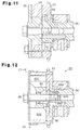
- vane type VVTs have a structure as shown in Figure 12 and 13.
- the VVT 80 is attached to the distal end of a camshaft 84.
- the camshaft 84 has a bolt hole 841 defined on the distal end, and a rotor 82 is fixed to that end by a bolt 85.
- a sprocket 81 surrounds the rotor 82 such that it can rotate relative to the rotor 82 and the camshaft 84.
- the sprocket 81 is connected to a crankshaft (not shown) by a chain (not shown).
- the sprocket 81 has a plurality of inward protrusions 811, and every adjacent two protrusions 811 define a recess 812.
- the rotor 82 has a plurality of vanes 821, and each vane 821 is housed in one of the recesses 812.
- Each vane 821 defines on each side a first hydraulic chamber 831 and a second hydraulic chamber 832 in the corresponding recess 812.
- the camshaft 84 receives a torque from the VVT 80 at its distal end.
- the camshaft 84 contains many hollow spaces including the oil passages 842, 843 and the bolt hole 841, the camshaft 84 tends to have insufficient rigidity against the torque.
- the camshaft 84 has a smaller diameter at the journal 844 than at other portions, the rigidity of the journal 844 is lower than that of the other portions.
- the oil passages 842, 843 open on the same plane, i.e., on the end face 86 of the camshaft 84, and the openings of these oil passages 842, 843 are close to one another. Accordingly, it is difficult to seal between the oil passage 842 and the oil passage 843, and the oil supplied to the oil passages 842 can leak into the oil passages 843 or, the oil supplied to the oil passages 843 can leak to the oil passages 842. If leakage occurs, the desired oil pressure values are not attained in the hydraulic chambers 831, 832, which deteriorates the response of the VVT 80.
- the present invention was accomplished in view of such circumstances described above, and it is an objective of the invention to provide a variable valve timing mechanism, which is driven by hydraulic fluid pressure, more specifically, a variable valve timing mechanism for an engine, which employs a camshaft having improved rigidity and which can reduce leakage of hydraulic fluid supplied to the respective pressure chambers.
- apparatus includes a camshaft for driving the intake valves or the exhaust valves, the camshaft having a distal end face, a first rotor fixed to the distal end face of the camshaft, the first rotor having vanes protruding radially outward, a second rotor disposed to surround the first rotor to be rotatable relative to the first rotor; the second rotor having recesses on the inner circumference, each recess being divided by the vane into a first pressure chamber and a second pressure chamber, a first passage defined in the camshaft, for supplying a fluid pressure to the first pressure chamber so as to change the rotational phase of the second rotor with respect to the camshaft, the first passage having an opening at the distal end face of the camshaft, and a second passage defined in the camshaft, for supplying a fluid pressure to the second pressure chamber so as to change the rotational phase of the second rotor with respect to the camshaft, the second passage having an
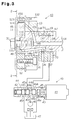
- variable valve timing mechanism (hereinafter referred to as VVT) according to a first embodiment of the present invention will be described below referring to Figures 1 to 3.
- an intake side camshaft 14 and a exhaust side camshaft 70 are supported rotatably on a cylinder head 79.
- the terms “left” and “right” are used herein to refer to the leftward and rightward direction of Fig. 1.
- the terms “clockwise” and “counterclockwise” refer to the perspective of Fig. 2.
- the camshafts 14,70 each have a plurality of cams 75.
- An intake valve 77 is located under each cam 75 of the camshaft 14, whereas an exhaust valve 78 is located under each cam 75 of the camshaft 70.
- a VVT 10 is attached to the end of the intake side camshaft 14.
- a drive gear 74 which is attached to the left end of the exhaust camshaft 70 is meshed with a driven gear 13 attached to the distal end portion of the intake side camshaft 14.
- a pulley 71 is attached to the right end of the exhaust camshaft 70 and is connected to a pulley 76 of a crankshaft 73 via a timing belt 72.
- the exhaust camshaft 70 When the crankshaft 73 is rotated, the exhaust camshaft 70 is rotated via the pulleys 76,71 and the belt 72. The torque of the exhaust camshaft 70 is transmitted to the intake camshaft 14 via the gears 74, 13 to rotate the camshaft 14. Thus, the intake valves 77 and the exhaust valves 78 are opened and closed under predetermined valve timings by the rotation of these camshafts 14 and 70.
- the VVT 10 contains the camshaft 14, a rotor 11 fixed to the left end of the camshaft 14, a housing 12 surrounding the rotor 11, the driven gear 13 fixed to the housing 12 and a cover 15 covering the housing 12.
- the camshaft 14 has a journal 141, and the camshaft 14 is supported at the journal 141 by the cylinder head 79 and a bearing cap 67.
- the camshaft 14 has a bolt hole 143 at the left end.
- the rotor 11 and the cover 15 are fixed to the left end of the camshaft 14 by a bolt 30 and are rotated integrally with the camshaft 14.
- the housing 12 surrounds the rotor 11 and is rotatable relative to the camshaft 14 and the rotor 11.
- the cover 15 has a flange 151 covering the housing 12.
- the driven gear 13 is fixed to one side of the housing 12 by bolts 31 to be rotatable relative to the camshaft 14 and the rotor 11.
- the driven gear 13 has a thick ring-like shape and has a plurality of teeth 132 formed on the circumference.
- the driven gear 13 is rotatably supported on outer surface 149 of the camshaft 14.
- the housing 12 and the rotor 11 are rotated clockwise.
- the housing 12 and that of the rotor 11 shown in Figure 2 are in their initial positions where the valve timing of the intake valves 77 (shown in Figure 1) is delayed most.
- the housing 12 has four inward protrusions 121, and every adjacent two protrusions 121 define a recess 122.
- the driven gear 13 is fixed by the bolts 31 to the protrusions 121 of the housing 12.
- the rotor 11 consists of a boss 48 and four vanes 112 protruding therefrom radially outward.
- the outer circumference of the boss 48 is brought into contact with the end faces of the protrusions 121.
- These four vanes 112 are arranged at approximately 90 degree intervals, and the vanes 112 are housed in the recesses 112 of the housing 12 respectively.
- Each vane 112 defines, in the corresponding recess 122, a first hydraulic chamber 101 and a second hydraulic chamber 102.
- the first hydraulic chamber 101 is located on the trailing side with respect to the rotating direction of the vane 112, while the second hydraulic chamber 102 is located on the leading side.
- Oil pressure is supplied to the hydraulic chambers 101, 102 respectively so as to effect relative rotation of the rotor 11 with respect to the housing 12.
- a seal 123 and a leaf spring 124 for urging the seal 123 toward the inner circumference of the housing 12 are attached to the distal end of each vane 112. The seal 123 and the leaf spring 124 seal between the first hydraulic chamber 101 and the second hydraulic chamber 102.
- two oil passages 145, 147 are defined in the camshaft 14 in the axial direction.
- two oil passages 36, 37 are defined in the cylinder head 79.
- Ring-like oil grooves 18, 19 are formed on the inner surfaces of the cylinder head 79 and the bearing cap 67.
- An oil hole 144, which is defined in the camshaft 14, connects the oil passage 145 and the oil groove 36; while another oil hole 146, which is also defined in the camshaft 14, connects the oil passage 147 and the oil groove 19.
- An annular chamber 114 is defined around the left end portion of the camshaft 14.
- the boss 48 of the rotor 11 has four passages 115 defined radially therein, and each passage 115 secures communication between the annular chamber 114 and the first hydraulic chambers 101 ( Figure 2).
- the camshaft 14 has a ring-like oil groove 142 formed on its outer surface 149. Another oil hole 148, which is also defined in the camshaft 14, connects the oil passage 147 and the oil groove 142.
- the driven gear 13 contains four passages 134 defined radially therein, and these passages 134 connects the oil groove 142 and the second hydraulic chambers 102 ( Figure 2). Oil is supplied to the first hydraulic chambers 101 through the oil passage 36, the oil groove 18, the oil hole 144, the oil passage 145, the annular chamber 114 and the passages 115. Meanwhile, oil is supplied to the second hydraulic chambers 102 through the oil passage 37, the oil groove 19, the oil hole 146, the oil passage 147, the oil hole 148, the oil groove 142 and the passages 134.
- the camshaft 14 has some hollow spaces therein, only the oil passage 145 and the bolt hole 143 open to the left end face of the camshaft 14, and the oil groove 142 opens to the outer surface 149 of the camshaft 14.
- a small clearance for permitting relative rotation between the camshaft 14 and the driven gear 13 is defined between the outer surface 149 of the camshaft 14 and the inner surface 133 of the driven gear 13.
- an oil control valve (hereinafter referred to as an OCV) 40 for supplying oil pressure to the first and second hydraulic chambers 101, 102 and of the VVT 10 will be described.
- the OCV 40 has a plurality of ports 45a, 45b, 45r, 45t to switch the direction of supplying and discharging the oil and to adjust the oil pressure supplied from the first port 45a and the second port 45b to the hydraulic chambers 101 and 102, respectively.
- the OCV 40 is provided with a solenoid actuator 41, a casing 45, a spool 44 disposed in the casing 45, a plunger 43 connected to the spool 44 and a coil spring 42 for urging the spool 44.
- the spool 44 is reciprocated in the axial direction by performing duty control of the actuator 41. This reciprocating motion of the spool 44 achieves adjustment of the amount of oil to be supplied.
- the supply port 45t is connected via a hydraulic pump 46 to an oil pan 47; while the first and the second ports 45a and 45b are connected to the oil passages 36 and 37 respectively.
- the drain port 45r is connected to the oil pan 47.
- the spool 44 is cylindrical valve body and has lands 44a, which interrupt the flow of the oil and passages 44b, 44c, which permit flow of the oil.
- the oil drawn or discharged by the pump 46 under the operation of the OCV 40 is supplied through the supply port 45t and the first port 45a to the oil passage 36 or through the supply port 45t and the second port 45b to the oil passage 37.
- the oil is supplied to the first hydraulic chambers 101 to increase the oil pressure in each hydraulic chamber 101.
- the oil in each second hydraulic chamber 102 is discharged through the oil passage 37 to the second port 45b to reduce the oil pressure in the second hydraulic chamber 102.
- the oil pressure in each second hydraulic chamber 102 is increased.
- the oil in each first hydraulic chamber 101 is discharged through the oil passage 36 to the first port 45a to reduce the oil pressure in the first hydraulic chamber 101.
- Introduction of the oil through the ports 45a, 45b or discharge of the oil through these ports 45a, 45b is interrupted by blocking them.
- the oil supplied to the oil groove 142 of the camshaft 14 is fed to the small clearance between the outer surface 149 of the camshaft 14 and the inner surface 133 of the driven gear 13 to facilitate smooth relative rotation of the camshaft 14 relative to the driven gear 13.
- valve timing of the intake valves 77 can be changed to the most delayed angle phase or to the most advanced angle phase by performing binary adjustment of the oil pressure values in the hydraulic chambers 101, 102 respectively under control of the OCV 40. Otherwise, the valve timing of the intake valves 77 may be changed continuously between the most delayed angle phase and the most advanced angle phase by continuously adjusting the oil pressure values in the hydraulic chambers 101, 102.
- the camshaft 14 of the first embodiment has less hollow space formed at the left end, so that the rigidity of the camshaft 14 is improved.
- the distance between the passage 115 opening to each first hydraulic chamber 101 and the passage 134 opening to each second hydraulic chamber 102 is increased compared with that of the prior art VVT. Accordingly, leakage of oil from the passages 134 to the first hydraulic chambers 101 or from the passages 115 to the second hydraulic chambers 102 is reduced, which reduces oil pressure interference between the hydraulic chambers 101 and 102. Thus, a desired oil pressure can be supplied to the hydraulic chambers 101 and 102, and the responsiveness of the VVT 10 is improved.
- the outside diameter ⁇ B at the distal end portion of a camshaft 14 is designed to be smaller than the outside diameter ⁇ A of the boss 38 of the rotor 11.
- the boundary between the outer circumference 149 of the camshaft 14 and the inner circumference 133 of the driven gear 13 is sealed by one side of the boss 38. Accordingly, that boundary is not exposed to the first and the second hydraulic chambers 101, 102 ( Figure 4).
- a small clearance permitting relative rotation between the camshaft 14 and the driven gear 13 is defined between the outer surface 149 of the camshaft 14 and the inner surface 133 of the driven gear 13. Smooth rotation of the camshaft 14 relative to the driven gear 13 is achieved by the oil supplied to the clearance.
- an intake side camshaft 25 the exhaust camshaft 70 and the crankshaft 73 are connected by a chain 29 to which a predetermined tension is applied by idlers 58, 59.
- the VVT 20 according to the third embodiment is attached to the left end of the intake side camshaft 25.
- the camshafts 25, 70 are rotated synchronously with the crankshaft 73 via the chain 29 and the sprockets 49, 21, 57, and the intake valves 77 and the exhaust valves 78 are driven under predetermined valve timings, respectively.
- the VVT 20 includes a rotor 22, a housing 24 surrounding the rotor 22, a sprocket 21 fixed to the housing 24 via a plate 23, and a cover 26 covering the housing 24.
- the camshaft 25 supported on the cylinder head 79 has a bolt hole 253 defined on the left end.
- the rotor 22 is fixed to that end of the camshaft 25 by a bolt 32 so that it is rotated integrally with the camshaft 25.
- the housing 24 surrounding the rotor 22 is rotatable relative to the camshaft 25 and the rotor 22.
- the cover 26, the plate 23 and the sprocket 21 are fixed by bolts 33 to the housing 24 so that they are rotated integrally.
- the rotor 22 has a boss 27 and four vanes 222, each of which defines a first hydraulic chamber 101 and a second hydraulic chamber 102 in a corresponding recess 242 of the housing 24.
- An annular chamber 221 is defined between the left end portion of the camshaft 25 and the rotor 22.
- the boss 27 of the rotor 22 has four passages 225 defined radially therein, and these passages 225 connect between the annular chamber 221 and the first hydraulic chambers 101.
- the diameter ⁇ A of the boss 27 of the rotor 22 is designed to be greater than the diameter ⁇ B at the left end portion of the camshaft 25.
- the boundary between the outer circumference 231 of the camshaft 25 and the inner circumference 211 of the plate 23 is sealed by the boss 27.
- the camshaft 25 contains an oil passage 255 defined axially therein, and the oil passage 255 opens at the left end to the annular chamber 221 and at the right to the oil hole 254.
- An annular chamber 213 is defined between the sprocket 21 and the plate 23 to connect an oil groove 252 formed on the outer circumference of the camshaft 25 with the oil holes 232.
- the camshaft 25 contains an oil passage 258 extending diagonally to connect the oil groove 252 and the bolt hole 253.
- the camshaft 25 has a radial oil passage 256 defined at the journal 251 thereof so as to communicate with the bolt hole 253.
- the clearance between the outer surface 231 of the camshaft 25 and the inner surface of the plate 23 is sealed by the boss 27 at the left end face of the camshaft 25, so that leakage of the oil from the clearance is substantially avoided. Accordingly, the desired oil pressure is supplied to the chambers 101 and 102 respectively, and the responsiveness and operability of the VVT 20 is improved.
- the distance between the passage 225 opening to the first hydraulic chamber 101 and the oil hole 232 opening to the second hydraulic chamber 102 is increased compared with that in the prior art VVT. Accordingly, oil leakage between the passage 225 and the oil hole 232 is substantially reduced, which results in more accurate operation of the VVT 20.
- the diameter of the housing 24 can be increased by increasing the diameter of the plate 23 without increasing the diameter of the sprocket 21.
- the force to be applied to each vane 22 can be increased. Accordingly, the driving force of the VVT 20 is increased while vibration of the rotor 22 attributed to fluctuation in the torque of the camshaft 25 is reduced. Thus, the responsiveness of the VVT 20 is improved.
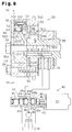
- VVT according to a fourth embodiment of the present invention will be described below referring to Figures 9 and 10. Differences from the third embodiment will primarily be described.
- the VVT of the fourth embodiment is applied to the same valve train as shown in Figure 6.
- the VVT 50 is provided with a lock pin 60 on one of four vanes 522.
- the lock pin 60 locks a rotor 52 relative to a sprocket 51 so as to retain the rotor 52 at the initial position of Fig. 10.
- Each passage 525 is defined in the rotor 52 to connect the annular chamber 221 to each of the first hydraulic chambers 101.
- One passage 525 opens to the first hydraulic chamber 101 and also to a releasing chamber 67 (to be described later).
- the lock pin 60 is housed in a lock pin hole 523.
- the lock pin 60 has a cylindrical shape and has a large diameter portion 61 and a small diameter portion 62.
- the lock pin 60 is urged by a spring 64, which urges the lock pin 60 toward a plate 53.
- the lock pin 60 has a first pressure receiving face 65, between the large diameter portion 61 and the small diameter portion 62, and a second pressure receiving face 66, which is at the end of the small diameter portion 62.
- the first pressure receiving surface 65 receives pressure from the oil supplied to the first hydraulic chambers 101, whereas the second pressure receiving surface 66 receives pressure from the oil supplied to the second hydraulic chambers 102.
- the lock pin 60 defines an annular releasing chamber 67, and the first pressure receiving surface 65 is opposed to the releasing chamber 67. Oil pressure is supplied through the passage 525 to the releasing chamber 67.
- the plate 53 contains a circular engaging hole 533 with which the lock pin 60 can engage.
- the second pressure receiving surface 66 of the lock pin 60 is opposed to the engaging hole 533.
- An annular chamber 534 is defined between the right side of the plate 53 and the left end of a camshaft 55.
- the annular chamber 534 communicates with each of second hydraulic chambers 102 via oil holes 532 and also with the engaging hole 533.
- An oil passage 558, communicating with the annular chamber 543, is defined in the camshaft 55, and this oil passage 558 is connected to the OCV 40 via another oil passage (not shown) defined in the camshaft 55.
- the rotor 52 When the engine is started, the rotor 52 is rotated integrally with the sprocket 51. Oil is gradually supplied to the hydraulic chambers 101, 102, and the oil pressure in the hydraulic chambers 101, 102 is unstable until they are filled. Meanwhile, the rotor 52 is subject to fluctuation in the torque of the camshaft 55. However, in the forth embodiment, since the movement of the rotor 52 is restricted by the lock pin 60, backlash of the rotor 52 is inhibited.
- the inner surface of the plate 53 which has the engaging hole 533 defined formed therein.
- the inner surface of the plate 53 is surface hardened.
- boron steel subjected to induction hardening, Cr steel or Cr-Mn steel subjected to hardening and tempering treatment and carburizing treatment may be suitably employed.
- Oil is supplied to the releasing chamber 67 or the engagement hole 533, although the pressure thereof is low when the engine is initially started. Accordingly, the lock pin 60 receives the pressure from oil at the first pressure receiving surface 65 or the second pressure receiving surface 66, and when the oil pressure is high enough, the lock pin 60 is disengaged from the engaging hole 533 against the urging force of the spring 64. Thus, after the oil pressure reaches a certain level, the engagement of the lock pin 60 with the engaging hole 533 is released to permit the rotor 52 to rotate relative to the sprocket 51. Once a sufficient oil pressure is reached, the lock pin 60 is maintained in the disengaged state until the engine is stopped.
- the rotor 52 and the camshaft 55 are rotated relative to the sprocket 51 by supplying oil to either the first hydraulic chambers 101 or the second hydraulic chambers 102 (with the pin 60 retracted), and thus the valve timing of the valves 77 ( Figure 6) driven by the camshaft 55 can be changed.
- the VVT 50 is provided with a surface-hardened plate 53, damage to the plate 53 is prevented even if the lock pin 60 are frequently brought into contact with the inner surface of the plate 53.
- the sprocket 51, the housing 54 and the plate 53 are fixed by a bolt 34.
- the plates 23 and 53 in the third embodiment and the fourth embodiment may be omitted.
- an annular chamber 69 can be formed as shown.
- valve timing of the intake valves 77 is changed, it is also possible to change the valve timing of the exhaust valves by attaching the VVT to the exhaust side camshaft.
- the pulley 71 can be connected to the right end of the intake camshaft 14, and the pulley 71 can be connected to the pulley 76 of the crankshaft 73 by the belt 72.
- the intake camshaft 14 is rotated synchronously with the crankshaft 73.
- the rotational phase of the exhaust side camshaft can be changed 70 relative to the crankshaft 73.
- a variable valve timing mechanism is provided at the distal end of a camshaft (14; 25; 39; 55) for changing a valve timing of an engine valve (77).
- a rotor (11; 22; 52) is fixed to the distal end face of the camshaft (14; 25; 39; 55), and the rotor has four vanes (112; 222; 522) protruding radially outward.
- a housing (12; 24; 54) is disposed to surround the rotor (11; 22; 52) to be rotatable relative to the rotor (11; 22; 52) and the camshaft (14; 25; 39; 55), and the housing (12; 24; 54) has recesses (122; 242; 542) on the inner circumference.
- Each recess (122; 242; 542) is divided by the vane (112; 222; 522) into a first pressure chamber (101) and a second pressure chamber (102).
- a first passage (145; 255; 555) is defined in the camshaft (14; 25; 39; 55), for supplying a hydraulic fluid pressure to the first pressure chamber (101) so as to change the rotational phase of the second rotor (12, 13; 21, 23, 24; 51, 53, 54) with respect to the camshaft (14; 25; 39; 55), and the first passage (145; 255; 555) has an opening at the distal end face of the camshaft (14; 25; 39; 55).
- a second passage (148; 258; 558) is defined in the camshaft (14; 25; 39; 55), for supplying a fluid pressure to the second pressure chamber (102) so as to change the rotational phase of the second rotor (12, 13; 21, 23, 24; 51, 53, 54) with respect to the camshaft (14; 25; 39; 55), and the second passage (148; 258; 558) has an opening at outer circumference (149; 231) of the camshaft (14; 25; 39; 55).
Landscapes
- Engineering & Computer Science (AREA)
- Mechanical Engineering (AREA)
- General Engineering & Computer Science (AREA)
- Chemical & Material Sciences (AREA)
- Combustion & Propulsion (AREA)
- Physics & Mathematics (AREA)
- Geometry (AREA)
- Valve Device For Special Equipments (AREA)
- Valve-Gear Or Valve Arrangements (AREA)
- Output Control And Ontrol Of Special Type Engine (AREA)
Applications Claiming Priority (6)
| Application Number | Priority Date | Filing Date | Title |
|---|---|---|---|
| JP86481/96 | 1996-04-09 | ||
| JP8648196 | 1996-04-09 | ||
| JP8648196 | 1996-04-09 | ||
| JP64123/97 | 1997-03-18 | ||
| JP6412397 | 1997-03-18 | ||
| JP09064123A JP3077621B2 (ja) | 1996-04-09 | 1997-03-18 | 内燃機関の可変バルブタイミング機構 |
Publications (2)
| Publication Number | Publication Date |
|---|---|
| EP0801212A1 true EP0801212A1 (fr) | 1997-10-15 |
| EP0801212B1 EP0801212B1 (fr) | 2000-07-26 |
Family
ID=26405258
Family Applications (1)
| Application Number | Title | Priority Date | Filing Date |
|---|---|---|---|
| EP97105771A Expired - Lifetime EP0801212B1 (fr) | 1996-04-09 | 1997-04-08 | Dispositif variable de commande des soupapes d'un moteur à combustion interne |
Country Status (7)
| Country | Link |
|---|---|
| US (1) | US5724929A (fr) |
| EP (1) | EP0801212B1 (fr) |
| JP (1) | JP3077621B2 (fr) |
| KR (1) | KR100265982B1 (fr) |
| CN (1) | CN1090277C (fr) |
| DE (1) | DE69702633T2 (fr) |
| ID (1) | ID18168A (fr) |
Cited By (11)
| Publication number | Priority date | Publication date | Assignee | Title |
|---|---|---|---|---|
| DE19903594A1 (de) * | 1998-02-03 | 1999-08-12 | Toyota Motor Co Ltd | Verstellbare Ventilsteuervorrichtung |
| WO2000061920A1 (fr) | 1999-04-14 | 2000-10-19 | Daimlerchrysler Ag | Dispositif d'ajustage angulaire relatif d'un arbre a cames |
| US6173687B1 (en) | 1997-11-14 | 2001-01-16 | Mitsubishi Denki Kabushiki Kaisha | Hydraulic apparatus for adjusting the timing of opening and closing of an engine valve |
| WO2001011202A1 (fr) * | 1999-08-04 | 2001-02-15 | INA Wälzlager Schaeffler oHG | Dispositif de variation des temps de commande de soupapes d'un moteur a combustion, en particulier dispositif de reglage de l'arbre a cames avec roue a ailettes pivotantes |
| DE19938596A1 (de) * | 1999-08-14 | 2001-02-15 | Schaeffler Waelzlager Ohg | Vorrichtung zur Drehwinkelverstellung einer Nockenwelle gegenüber der Kurbelwelle eines Verbrennungsmotors |
| DE19951391A1 (de) * | 1999-10-26 | 2001-07-05 | Schaeffler Waelzlager Ohg | Vorrichtung zum Verändern der Steuerzeiten von Gaswechselventilen einer Brennkraftmaschine, insbesondere hydraulische Nockenwellen-Verstelleinrichtung in Rotationsrichtung |
| EP1286023A3 (fr) * | 2001-08-14 | 2003-08-20 | BorgWarner Inc. | Déphaseur pour un moteur à combustion interne à quatre cylindre |
| DE10045418B4 (de) * | 1999-09-17 | 2006-01-12 | Hitachi, Ltd. | Vorrichtung zur Steuerung der Ventileinstellung für Brennkraftmaschinen |
| WO2006125536A1 (fr) * | 2005-05-23 | 2006-11-30 | Schaeffler Kg | Dispositif de reglage variable des temps de commande de soupapes d'echange gazeux d'un moteur a combustion interne |
| WO2010003745A1 (fr) * | 2008-07-07 | 2010-01-14 | Schaeffler Kg | Déphaseur d'arbre à cames |
| WO2011061100A1 (fr) * | 2009-11-17 | 2011-05-26 | Schaeffler Technologies Gmbh & Co. Kg | Rotor, en particulier pour un déphaseur d'arbre à cames, procédé pour produire un rotor et dispositif pour ajuster l'angle de rotation d'un arbre à cames par rapport à un vilebrequin d'un moteur |
Families Citing this family (40)
| Publication number | Priority date | Publication date | Assignee | Title |
|---|---|---|---|---|
| JP3116858B2 (ja) * | 1996-11-29 | 2000-12-11 | トヨタ自動車株式会社 | 内燃機関のバルブタイミング可変機構 |
| EP1229216B1 (fr) * | 1996-12-12 | 2004-09-29 | Aisin Seiki Kabushiki Kaisha | Dispositif de commande de soupape |
| JP3812689B2 (ja) * | 1996-12-12 | 2006-08-23 | アイシン精機株式会社 | 弁開閉時期制御装置 |
| JP3029020B2 (ja) * | 1997-04-25 | 2000-04-04 | 株式会社デンソー | 内燃機関用バルブタイミング調整装置 |
| JP3760566B2 (ja) * | 1997-06-05 | 2006-03-29 | アイシン精機株式会社 | 弁開閉時期制御装置 |
| JP3760568B2 (ja) * | 1997-06-05 | 2006-03-29 | アイシン精機株式会社 | 弁開閉時期制御装置 |
| JP3823451B2 (ja) * | 1997-06-24 | 2006-09-20 | アイシン精機株式会社 | 弁開閉時期制御装置 |
| JP3191730B2 (ja) * | 1997-07-17 | 2001-07-23 | 三菱電機株式会社 | 油圧式バルブタイミング調節装置 |
| US6170447B1 (en) * | 1997-11-06 | 2001-01-09 | Ina Schaeffler Ohg | Inner seal for a camshaft adjusting device in an internal combustion engine, specially a blade cell adjusting device |
| DE19808618A1 (de) * | 1998-02-28 | 1999-09-02 | Schaeffler Waelzlager Ohg | Verriegelungseinrichtung für eine Vorrichtung zum Verändern der Steuerzeiten von Gaswechselventilen einer Brennkraftmaschine, insbesondere für eine Flügelzellen-Verstelleinrichtung |
| WO2002061241A1 (fr) * | 2001-01-29 | 2002-08-08 | Unisia Jecs Corporation | Controleur de reglage de distribution d'un moteur a combustion interne |
| DE10213081A1 (de) * | 2002-03-20 | 2003-10-02 | Hydraulik Ring Gmbh | Ventilsteuerung zur Einstellung des Hubes von Ventilen in Kraftfahrzeugen |
| JP2004263643A (ja) * | 2003-03-03 | 2004-09-24 | Mitsubishi Electric Corp | バルブタイミング調整装置 |
| JP4177197B2 (ja) * | 2003-08-08 | 2008-11-05 | 株式会社日立製作所 | 内燃機関のバルブタイミング制御装置 |
| JP2005061261A (ja) * | 2003-08-08 | 2005-03-10 | Hitachi Unisia Automotive Ltd | 内燃機関の可変動弁装置 |
| JP4055691B2 (ja) * | 2003-10-03 | 2008-03-05 | 松下電器産業株式会社 | 産業用ロボット |
| DE10356908B4 (de) * | 2003-12-02 | 2007-11-22 | Hydraulik-Ring Gmbh | Nockenwellenverstelleinrichtung für Verbrennungskraftmaschinen von Fahrzeugen, vorzugsweise Kraftfahrzeugen |
| DE102005026553B3 (de) * | 2005-06-08 | 2006-09-07 | Hydraulik-Ring Gmbh | Schwenkmotor mit verringerter Leckage |
| DE102006049243A1 (de) * | 2006-10-18 | 2008-04-24 | Mahle International Gmbh | Betätigungseinrichtung für zwei parallel drehende Nockenwellen |
| JP4697547B2 (ja) * | 2006-11-13 | 2011-06-08 | 株式会社デンソー | バルブタイミング調整装置 |
| DE102007054547A1 (de) * | 2007-11-15 | 2009-05-20 | Schaeffler Kg | Motorsteuerstrategie für hydraulischen Nockenwellenversteller mit mechanischer Mittenverriegelung |
| JP5093587B2 (ja) * | 2007-12-07 | 2012-12-12 | アイシン精機株式会社 | 弁開閉時期制御装置 |
| JP2010236448A (ja) * | 2009-03-31 | 2010-10-21 | Yamaha Motor Co Ltd | 水ジェット推進艇 |
| JP2010242612A (ja) * | 2009-04-06 | 2010-10-28 | Yamaha Motor Co Ltd | 水ジェット推進艇 |
| JP4900451B2 (ja) * | 2009-11-09 | 2012-03-21 | 株式会社デンソー | バルブタイミング調整装置 |
| WO2011081993A2 (fr) | 2010-01-04 | 2011-07-07 | Borgwarner Inc. | Déphaseur à pression d'huile |
| KR101271897B1 (ko) * | 2010-01-14 | 2013-06-05 | 미쯔비시 지도샤 고교 가부시끼가이샤 | 가변동 밸브 장치 부착 엔진 |
| JP5182326B2 (ja) * | 2010-06-09 | 2013-04-17 | トヨタ自動車株式会社 | 流量制御弁 |
| JP5569458B2 (ja) * | 2011-04-18 | 2014-08-13 | 株式会社デンソー | バルブタイミング調整装置 |
| US9284861B2 (en) * | 2011-08-30 | 2016-03-15 | Borgwarner, Inc. | Oil passage design for a phaser or dual phaser |
| DE102012201563A1 (de) * | 2012-02-02 | 2013-08-08 | Schaeffler Technologies AG & Co. KG | Rückschlagventil für Nockenwellenversteller mit Ölspeicher |
| DE102012025791B3 (de) * | 2012-02-02 | 2021-03-25 | Schaeffler Technologies AG & Co. KG | Anordnung eines Volumenspeichers im Nockenwellenversteller |
| CN103375212B (zh) * | 2012-04-26 | 2016-12-28 | 日立汽车系统株式会社 | 内燃机的可变气门装置 |
| CN102935584B (zh) * | 2012-11-21 | 2014-11-05 | 武汉船用机械有限责任公司 | 一种配油器壳体的加工方法 |
| CN104179542B (zh) * | 2013-05-24 | 2018-08-21 | 舍弗勒技术股份两合公司 | 凸轮轴相位调节器及其转子以及可变凸轮正时系统 |
| DE102013221886A1 (de) | 2013-10-28 | 2015-04-30 | Borgwarner Inc. | Brennkraftmaschine mit einem Phasenversteller sowie dazugehöriges Regelverfahren |
| DE102014208598B4 (de) * | 2014-05-08 | 2020-10-29 | Schaeffler Technologies AG & Co. KG | Nockenwellenversteller mit zum Erreichen eines hydraulischen Freilaufs hin- und herschaltbarem Hydraulikkammerabdichtelement |
| CN104455944A (zh) * | 2014-11-29 | 2015-03-25 | 南京萨伯工业设计研究院有限公司 | 马达壳体及其加工方法 |
| CN105736083A (zh) * | 2014-12-12 | 2016-07-06 | 舍弗勒技术股份两合公司 | 凸轮轴相位调节器 |
| CN112796849B (zh) * | 2019-11-14 | 2024-05-17 | 舍弗勒投资(中国)有限公司 | 用于凸轮轴调相器的转子和凸轮轴调相器 |
Citations (3)
| Publication number | Priority date | Publication date | Assignee | Title |
|---|---|---|---|---|
| FR1085087A (fr) * | 1953-06-17 | 1955-01-27 | Dispositif de commande du déplacement angulaire relatif de deux parties co-axiales d'une transmission | |
| US4858572A (en) * | 1987-09-30 | 1989-08-22 | Aisin Seiki Kabushiki Kaisha | Device for adjusting an angular phase difference between two elements |
| JPH05113112A (ja) * | 1991-10-24 | 1993-05-07 | Toyo A Tec Kk | エンジンの弁開閉時期可変装置 |
Family Cites Families (4)
| Publication number | Priority date | Publication date | Assignee | Title |
|---|---|---|---|---|
| JPS5429011B2 (fr) * | 1974-07-21 | 1979-09-20 | ||
| US5107804A (en) * | 1989-10-16 | 1992-04-28 | Borg-Warner Automotive Transmission & Engine Components Corporation | Variable camshaft timing for internal combustion engine |
| JPH0511312A (ja) * | 1991-07-04 | 1993-01-22 | Nikon Corp | カメラの露出制御装置 |
| US5666914A (en) | 1994-05-13 | 1997-09-16 | Nippondenso Co., Ltd. | Vane type angular phase adjusting device |
-
1997
- 1997-03-18 JP JP09064123A patent/JP3077621B2/ja not_active Expired - Fee Related
- 1997-04-07 ID IDP971164A patent/ID18168A/id unknown
- 1997-04-07 US US08/835,252 patent/US5724929A/en not_active Expired - Lifetime
- 1997-04-08 DE DE69702633T patent/DE69702633T2/de not_active Expired - Lifetime
- 1997-04-08 KR KR1019970012776A patent/KR100265982B1/ko not_active Expired - Lifetime
- 1997-04-08 EP EP97105771A patent/EP0801212B1/fr not_active Expired - Lifetime
- 1997-04-09 CN CN97111244A patent/CN1090277C/zh not_active Expired - Lifetime
Patent Citations (3)
| Publication number | Priority date | Publication date | Assignee | Title |
|---|---|---|---|---|
| FR1085087A (fr) * | 1953-06-17 | 1955-01-27 | Dispositif de commande du déplacement angulaire relatif de deux parties co-axiales d'une transmission | |
| US4858572A (en) * | 1987-09-30 | 1989-08-22 | Aisin Seiki Kabushiki Kaisha | Device for adjusting an angular phase difference between two elements |
| JPH05113112A (ja) * | 1991-10-24 | 1993-05-07 | Toyo A Tec Kk | エンジンの弁開閉時期可変装置 |
Non-Patent Citations (1)
| Title |
|---|
| PATENT ABSTRACTS OF JAPAN vol. 017, no. 479 (M - 1471) 31 August 1993 (1993-08-31) * |
Cited By (21)
| Publication number | Priority date | Publication date | Assignee | Title |
|---|---|---|---|---|
| US6173687B1 (en) | 1997-11-14 | 2001-01-16 | Mitsubishi Denki Kabushiki Kaisha | Hydraulic apparatus for adjusting the timing of opening and closing of an engine valve |
| DE19903594C2 (de) * | 1998-02-03 | 2003-06-18 | Toyota Motor Co Ltd | Verstellbare Ventilsteuervorrichtung |
| US6170448B1 (en) | 1998-02-03 | 2001-01-09 | Toyota Jidosha Kabushiki Kaisha | Variable valve timing apparatus |
| DE19903594A1 (de) * | 1998-02-03 | 1999-08-12 | Toyota Motor Co Ltd | Verstellbare Ventilsteuervorrichtung |
| WO2000061920A1 (fr) | 1999-04-14 | 2000-10-19 | Daimlerchrysler Ag | Dispositif d'ajustage angulaire relatif d'un arbre a cames |
| DE19916675A1 (de) * | 1999-04-14 | 2000-11-30 | Daimler Chrysler Ag | Vorrichtung zur relativen Winkelverstellung einer Nockenwelle |
| DE19916675B4 (de) * | 1999-04-14 | 2005-07-07 | Daimlerchrysler Ag | Vorrichtung zur relativen Winkelverstellung einer Nockenwelle |
| US6601554B1 (en) | 1999-08-04 | 2003-08-05 | Ina Walzlager Schaeffler Ohg | Device for varying the valve control times of an internal combustion engine, especially a camshaft adjusting device with a pivotal impeller wheel |
| WO2001011202A1 (fr) * | 1999-08-04 | 2001-02-15 | INA Wälzlager Schaeffler oHG | Dispositif de variation des temps de commande de soupapes d'un moteur a combustion, en particulier dispositif de reglage de l'arbre a cames avec roue a ailettes pivotantes |
| DE19938596A1 (de) * | 1999-08-14 | 2001-02-15 | Schaeffler Waelzlager Ohg | Vorrichtung zur Drehwinkelverstellung einer Nockenwelle gegenüber der Kurbelwelle eines Verbrennungsmotors |
| DE10045418B4 (de) * | 1999-09-17 | 2006-01-12 | Hitachi, Ltd. | Vorrichtung zur Steuerung der Ventileinstellung für Brennkraftmaschinen |
| DE19951391A1 (de) * | 1999-10-26 | 2001-07-05 | Schaeffler Waelzlager Ohg | Vorrichtung zum Verändern der Steuerzeiten von Gaswechselventilen einer Brennkraftmaschine, insbesondere hydraulische Nockenwellen-Verstelleinrichtung in Rotationsrichtung |
| US6418893B1 (en) | 1999-10-26 | 2002-07-16 | Ina Walzlager Schaeffler Ohg | Device for varying valve timing of gas exchange valves of an internal combustion engine, in particular a hydraulic camshaft adjusting device of a rotary piston type |
| EP1286023A3 (fr) * | 2001-08-14 | 2003-08-20 | BorgWarner Inc. | Déphaseur pour un moteur à combustion interne à quatre cylindre |
| US6763791B2 (en) | 2001-08-14 | 2004-07-20 | Borgwarner Inc. | Cam phaser for engines having two check valves in rotor between chambers and spool valve |
| WO2006125536A1 (fr) * | 2005-05-23 | 2006-11-30 | Schaeffler Kg | Dispositif de reglage variable des temps de commande de soupapes d'echange gazeux d'un moteur a combustion interne |
| US7707981B2 (en) | 2005-05-23 | 2010-05-04 | Schaeffler Kg | Device for the variable adjustment of the control times for gas exchange valves in an internal combustion engine |
| WO2010003745A1 (fr) * | 2008-07-07 | 2010-01-14 | Schaeffler Kg | Déphaseur d'arbre à cames |
| US8434438B2 (en) | 2008-07-07 | 2013-05-07 | Schaeffler Technologies AG & Co. KG | Camshaft adjuster |
| WO2011061100A1 (fr) * | 2009-11-17 | 2011-05-26 | Schaeffler Technologies Gmbh & Co. Kg | Rotor, en particulier pour un déphaseur d'arbre à cames, procédé pour produire un rotor et dispositif pour ajuster l'angle de rotation d'un arbre à cames par rapport à un vilebrequin d'un moteur |
| US8490589B2 (en) | 2009-11-17 | 2013-07-23 | Schaeffler Technologies AG & Co. KG | Rotor, in particular for a camshaft adjuster, method for producing a rotor and device for adjusting the angle of rotation of a camshaft relative to a crankshaft of an engine |
Also Published As
| Publication number | Publication date |
|---|---|
| CN1175658A (zh) | 1998-03-11 |
| KR19980076196A (ko) | 1998-11-16 |
| KR100265982B1 (ko) | 2000-10-02 |
| CN1090277C (zh) | 2002-09-04 |
| US5724929A (en) | 1998-03-10 |
| DE69702633D1 (de) | 2000-08-31 |
| DE69702633T2 (de) | 2001-04-05 |
| EP0801212B1 (fr) | 2000-07-26 |
| JPH09329005A (ja) | 1997-12-22 |
| JP3077621B2 (ja) | 2000-08-14 |
| ID18168A (id) | 1998-03-12 |
Similar Documents
| Publication | Publication Date | Title |
|---|---|---|
| US5724929A (en) | Engine variable valve timing mechanism | |
| EP0799977B1 (fr) | Dispositif de variations du calage des soupapes d'un moteur à combustion interne | |
| US6006708A (en) | Valve timing controlling apparatus for internal combustion engine | |
| EP2006500B1 (fr) | Déphaseur avec rotor à aubes et un pion de blocage | |
| EP1400661B1 (fr) | Mécanisme de déclenchement d'une broche de verrouillage pour déphaseur d'arbre à cames à commande par soupape à tiroir | |
| EP0915234B1 (fr) | Dispositif pour changer le calage de la distribution d'un moteur à combustion interne | |
| JP3116858B2 (ja) | 内燃機関のバルブタイミング可変機構 | |
| JP2947165B2 (ja) | 内燃機関のバルブタイミング変更装置 | |
| US5803029A (en) | Valve performance controller for internal combustion engine | |
| EP0821139B1 (fr) | Arrangement pour alimentation en huile d'un dispositif de variations du calage des soupapes | |
| EP0801211B1 (fr) | Mécanisme de commande variable du calage des soupapes de moteur à combustion interne | |
| US20030079703A1 (en) | Variable valve control apparatus for internal combustion engine and method thereof | |
| JPH10141022A (ja) | 内燃機関のバルブタイミング制御装置 | |
| EP0816643A1 (fr) | Actuateur hydraulique pour moteur à combustion interne | |
| JPH09250310A (ja) | 内燃機関のバルブタイミング変更装置 | |
| JP3627340B2 (ja) | 弁開閉時期制御装置 | |
| JP3085219B2 (ja) | 内燃機関のバルブタイミング制御装置 | |
| JPH10159519A (ja) | 内燃機関のバルブタイミング制御装置 | |
| JPH11280414A (ja) | 可変バルブタイミング装置付dohcエンジン | |
| JPH09250311A (ja) | 内燃機関のバルブタイミング変更装置 | |
| JP2950263B2 (ja) | 内燃機関のバルブタイミング制御装置 | |
| JP3221336B2 (ja) | 内燃機関のバルブタイミング制御装置 | |
| JPH10231712A (ja) | 内燃機関のバルブタイミング制御装置 | |
| JPH1113431A (ja) | 弁開閉時期制御装置 | |
| JPH10115203A (ja) | 内燃機関のバルブタイミング可変機構 |
Legal Events
| Date | Code | Title | Description |
|---|---|---|---|
| PUAI | Public reference made under article 153(3) epc to a published international application that has entered the european phase |
Free format text: ORIGINAL CODE: 0009012 |
|
| 17P | Request for examination filed |
Effective date: 19970408 |
|
| AK | Designated contracting states |
Kind code of ref document: A1 Designated state(s): DE FR GB |
|
| 17Q | First examination report despatched |
Effective date: 19980331 |
|
| GRAG | Despatch of communication of intention to grant |
Free format text: ORIGINAL CODE: EPIDOS AGRA |
|
| GRAG | Despatch of communication of intention to grant |
Free format text: ORIGINAL CODE: EPIDOS AGRA |
|
| GRAH | Despatch of communication of intention to grant a patent |
Free format text: ORIGINAL CODE: EPIDOS IGRA |
|
| GRAH | Despatch of communication of intention to grant a patent |
Free format text: ORIGINAL CODE: EPIDOS IGRA |
|
| GRAA | (expected) grant |
Free format text: ORIGINAL CODE: 0009210 |
|
| AK | Designated contracting states |
Kind code of ref document: B1 Designated state(s): DE FR GB |
|
| ET | Fr: translation filed | ||
| REF | Corresponds to: |
Ref document number: 69702633 Country of ref document: DE Date of ref document: 20000831 |
|
| PLBE | No opposition filed within time limit |
Free format text: ORIGINAL CODE: 0009261 |
|
| STAA | Information on the status of an ep patent application or granted ep patent |
Free format text: STATUS: NO OPPOSITION FILED WITHIN TIME LIMIT |
|
| 26N | No opposition filed | ||
| REG | Reference to a national code |
Ref country code: GB Ref legal event code: IF02 |
|
| REG | Reference to a national code |
Ref country code: GB Ref legal event code: 746 Effective date: 20130128 |
|
| REG | Reference to a national code |
Ref country code: DE Ref legal event code: R084 Ref document number: 69702633 Country of ref document: DE Effective date: 20130125 |
|
| REG | Reference to a national code |
Ref country code: FR Ref legal event code: PLFP Year of fee payment: 20 |
|
| PGFP | Annual fee paid to national office [announced via postgrant information from national office to epo] |
Ref country code: FR Payment date: 20160309 Year of fee payment: 20 |
|
| PGFP | Annual fee paid to national office [announced via postgrant information from national office to epo] |
Ref country code: DE Payment date: 20160405 Year of fee payment: 20 Ref country code: GB Payment date: 20160406 Year of fee payment: 20 |
|
| REG | Reference to a national code |
Ref country code: DE Ref legal event code: R071 Ref document number: 69702633 Country of ref document: DE |
|
| REG | Reference to a national code |
Ref country code: GB Ref legal event code: PE20 Expiry date: 20170407 |
|
| PG25 | Lapsed in a contracting state [announced via postgrant information from national office to epo] |
Ref country code: GB Free format text: LAPSE BECAUSE OF EXPIRATION OF PROTECTION Effective date: 20170407 |