EP0801294A1 - Mesure de courant d'ions à haute fréquence aprés allumage à courant alternatif - Google Patents
Mesure de courant d'ions à haute fréquence aprés allumage à courant alternatif Download PDFInfo
- Publication number
- EP0801294A1 EP0801294A1 EP97105505A EP97105505A EP0801294A1 EP 0801294 A1 EP0801294 A1 EP 0801294A1 EP 97105505 A EP97105505 A EP 97105505A EP 97105505 A EP97105505 A EP 97105505A EP 0801294 A1 EP0801294 A1 EP 0801294A1
- Authority
- EP
- European Patent Office
- Prior art keywords
- ignition
- circuit
- voltage
- frequency
- current
- Prior art date
- Legal status (The legal status is an assumption and is not a legal conclusion. Google has not performed a legal analysis and makes no representation as to the accuracy of the status listed.)
- Granted
Links
Images

Classifications
-
- F—MECHANICAL ENGINEERING; LIGHTING; HEATING; WEAPONS; BLASTING
- F02—COMBUSTION ENGINES; HOT-GAS OR COMBUSTION-PRODUCT ENGINE PLANTS
- F02P—IGNITION, OTHER THAN COMPRESSION IGNITION, FOR INTERNAL-COMBUSTION ENGINES; TESTING OF IGNITION TIMING IN COMPRESSION-IGNITION ENGINES
- F02P17/00—Testing of ignition installations, e.g. in combination with adjusting; Testing of ignition timing in compression-ignition engines
- F02P17/12—Testing characteristics of the spark, ignition voltage or current
-
- G—PHYSICS
- G01—MEASURING; TESTING
- G01L—MEASURING FORCE, STRESS, TORQUE, WORK, MECHANICAL POWER, MECHANICAL EFFICIENCY, OR FLUID PRESSURE
- G01L23/00—Devices or apparatus for measuring or indicating or recording rapid changes, such as oscillations, in the pressure of steam, gas, or liquid; Indicators for determining work or energy of steam, internal-combustion, or other fluid-pressure engines from the condition of the working fluid
- G01L23/22—Devices or apparatus for measuring or indicating or recording rapid changes, such as oscillations, in the pressure of steam, gas, or liquid; Indicators for determining work or energy of steam, internal-combustion, or other fluid-pressure engines from the condition of the working fluid for detecting or indicating knocks in internal-combustion engines; Units comprising pressure-sensitive members combined with ignitors for firing internal-combustion engines
- G01L23/221—Devices or apparatus for measuring or indicating or recording rapid changes, such as oscillations, in the pressure of steam, gas, or liquid; Indicators for determining work or energy of steam, internal-combustion, or other fluid-pressure engines from the condition of the working fluid for detecting or indicating knocks in internal-combustion engines; Units comprising pressure-sensitive members combined with ignitors for firing internal-combustion engines for detecting or indicating knocks in internal combustion engines
-
- F—MECHANICAL ENGINEERING; LIGHTING; HEATING; WEAPONS; BLASTING
- F02—COMBUSTION ENGINES; HOT-GAS OR COMBUSTION-PRODUCT ENGINE PLANTS
- F02P—IGNITION, OTHER THAN COMPRESSION IGNITION, FOR INTERNAL-COMBUSTION ENGINES; TESTING OF IGNITION TIMING IN COMPRESSION-IGNITION ENGINES
- F02P17/00—Testing of ignition installations, e.g. in combination with adjusting; Testing of ignition timing in compression-ignition engines
- F02P17/12—Testing characteristics of the spark, ignition voltage or current
- F02P2017/125—Measuring ionisation of combustion gas, e.g. by using ignition circuits
- F02P2017/128—Measuring ionisation of combustion gas, e.g. by using ignition circuits for knock detection
-
- F—MECHANICAL ENGINEERING; LIGHTING; HEATING; WEAPONS; BLASTING
- F02—COMBUSTION ENGINES; HOT-GAS OR COMBUSTION-PRODUCT ENGINE PLANTS
- F02P—IGNITION, OTHER THAN COMPRESSION IGNITION, FOR INTERNAL-COMBUSTION ENGINES; TESTING OF IGNITION TIMING IN COMPRESSION-IGNITION ENGINES
- F02P3/00—Other installations
- F02P3/02—Other installations having inductive energy storage, e.g. arrangements of induction coils
- F02P3/04—Layout of circuits
- F02P3/0407—Opening or closing the primary coil circuit with electronic switching means
- F02P3/0435—Opening or closing the primary coil circuit with electronic switching means with semiconductor devices
- F02P3/0442—Opening or closing the primary coil circuit with electronic switching means with semiconductor devices using digital techniques
Definitions
- the invention relates to a circuit arrangement for ion current measurement according to the preamble of claim 1, as is known from the generic, not previously published document DE 195 24 539 and which is used for knock detection.
- Knocking refers to undesirable combustion processes in an internal combustion engine, which are usually caused by auto-ignition of the fuel and produce a knock-like engine noise. In addition to a reduction in performance, an increase in fuel consumption and exhaust emissions, engine knocking can cause serious engine damage.
- One possibility of detecting engine knock is to carry out an ion current measurement in the combustion chamber of an internal combustion engine.
- a circuit arrangement for ion current measurement in cooperation with a conventional transistor ignition is already known from DE 33 27 766 A1.
- a spark plug serving as an ion current probe is arranged in the combustion chamber of each cylinder.
- a pulse-shaped alternating voltage is generated on the primary side of the ignition coil by an excitation voltage generator, which is fed to the control electrode of the ignition transistor and is coupled into the combustion chamber on the secondary side via the spark plug.
- the pulsed alternating voltage is modulated depending on the combustion chamber pressure, coupled out on the secondary side and processed in an evaluation circuit.
- the disadvantage of this known circuit arrangement is the connection of the ion current measurement with a conventional translator ignition.
- a transistor ignition With a transistor ignition, the ignition timing and the duration of the ignition spark can only be changed to a very limited extent.
- the spark plug burn time is approx. 1 ms, whereby the crankshaft rotates approx. 36 degrees (approx. 20% of the combustion cycle).
- the ion current measurement cannot be carried out during this period, which severely impairs the detection of irregular pressure profiles.
- a reduction of this problem can be achieved by combining the ion current measurement with the AC ignition.
- AC ignition is known, for example, from document DE 39 28 726 A1.
- This ignition system has a self-oscillating ignition output stage and a device for static and / or dynamic detection of the ignition angle.
- the ignition output stage which has an ignition coil with primary and secondary windings, a capacitor, a controllable semiconductor switch and a spark plug arranged in the circuit of the secondary winding, generates an alternating ignition current which is fed to the spark plug in a controllable manner. This allows free adjustment of the burning time and the burning time of the spark of a spark plug.
- a circuit arrangement for ion current measurement and for alternating current ignition has already been described in the above-mentioned document DE 195 24 539.
- an L / C resonant circuit is arranged on the primary side of the ignition coil, which generates an alternating voltage with a frequency required for the ignition during the ignition phase, which is used for the ion current measurement with a correspondingly small amplitude during the measurement phase.
- the duration of the spark can be reduced to such an extent that a meaningful ion current measurement can be carried out even at high engine speeds.
- the disadvantage of this circuit arrangement lies in the small frequency spacing between the resonant frequency of the resonant circuit and the frequency spectrum of the engine knock.
- the resonance frequency is adapted to the requirements of the ignition and is approximately 20 kHz, while the engine knock has a frequency spectrum of 8-18 kHz. Demodulating these two frequencies is only possible with great effort.
- the invention has for its object to provide a circuit arrangement for ion current measurement and for alternating current ignition, which avoids the disadvantages mentioned above
- the resonant circuit of a circuit arrangement which is used according to the document DE 195 24 539 for ion current measurement and for alternating current ignition, which consists of a capacitor arranged in the primary circuit of the ignition coil and the Primary winding of the ignition coil exists, and which generates an alternating voltage with the first frequency required for the ignition during the ignition phase, is expanded in such a way that the control unit drives the ignition transistor at high frequency with rectangular current pulses during the measurement phase, as a result of which a triangular current is impressed on the primary side of the ignition coil , which generates a sinusoidal AC voltage on the secondary side with a second frequency required for ion current measurement.
- An advantageous further development of the invention lies in the reduction of the dependency of the secondary-side, sinusoidal AC voltage on the instantaneous load on the secondary circuit.
- the pulse width of the high-frequency square-wave current pulses is regulated at a constant frequency.
- the load on the capacitor in the primary circuit of the ignition coil can be detected and evaluated as a controlled variable.
- the duration of the individual square-wave current pulses for generating the alternating voltage with the second frequency must be very short (a few hundred nanoseconds), and this can only be implemented with great effort in terms of circuitry a further advantageous development that the supply voltage of the circuit arrangement is reduced to the battery voltage or another available voltage during the measurement phase.
- the supply voltage of the circuit arrangement is also reduced during the measurement phase in order to reduce the amplitude of the sinusoidal alternating voltage on the secondary side to generate an ion current to such an extent that no undesired flashovers occur on the spark plug during the ion current measurement.
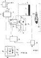
- the sequential activation of the spark plugs Zk makes it possible to use certain parts of the circuit arrangement for all of the cylinders, while other parts must be present separately for each cylinder.
- the ignition output stage Z contains an ignition coil T r with primary and secondary windings, the aforementioned spark plug Zk being connected to the secondary winding.
- the primary winding is connected with one connection to a supply voltage U V and with its other connection to the capacitor C to form an oscillating circuit.
- An energy recovery diode D 1 and a series circuit comprising an ignition transistor T and a current shunt R 1 are connected in parallel with the capacitor C.
- the ignition transistor T receives control signals from a control unit 1, which is also connected to the shunt resistor R 1 to detect the actual value of the current flowing through this ignition transistor T.
- the control unit 1 contains a pulse generator and a circuit for shaping rectangular signals.
- a control circuit 2 takes over the function of an engine management and is connected to the control unit 1 in order to ensure correct ignition distribution via this connection.
- this control circuit 2 is supplied with motor parameters such as load, speed and temperature via an input E.
- Corresponding actuators are controlled via outputs A.
- the ignition output stage Z works in current-controlled blocking and forward converter operation.
- a collector current I k flows , which corresponds to the primary coil current I p .
- This collector current I k is limited by the control unit 1 to a certain value I soll .
- the switched-mode power supply 5 in turn is supplied by the on-board voltage U B. If the collector current I k has reached the value specified by I soll , the ignition transistor T is switched off.
- the energy contained in the primary coil excites the secondary side of the ignition coil T r (secondary inductance, spark plug capacity) to vibrate. Due to the 50% coupling between the primary coil and the secondary coil of the ignition coil T r , part of the energy on the primary side of the ignition coil T r is transferred into the capacitor C and the other part on the secondary side of the ignition coil T r into the spark plug capacitance.
- the oscillation continues due to the only approx. 50% coupling between the primary and secondary inductance, and forms the secondary side AC voltage of the ignition phase Usek ZP .
- the ignition transistor T is switched on again, since the same voltage conditions now exist as before the ignition transistor T was switched on for the first time.
- the current control always supplies the same energy to the primary coil.
- the portion of the energy that was not used in the spark channel is completely fed back into the vehicle electrical system.
- the coupling of approx. 50% prevents total damping of the primary resonant circuit due to the strongly damped secondary resonant circuit in the event of a spark breakdown.
- the ignition transistor T is switched on by the control unit 1 as often or until the desired spark duration of the spark plug Zk is reached.
- the ignition transistor T is driven by the control unit 1 to carry out the ion current measurement within the measurement phase with rectangular current pulses of high frequency.
- a resonant circuit for generating and shaping small-signal rectangular pulses with a suitable amplifier stage is implemented within the control unit 1. The rectangular current pulses switch the ignition transistor T on and off continuously.
- the free formation of an oscillation on the primary side of the ignition coil T r is suppressed in that, before the transfer of the energy due to the coupling into the capacitor C, the ignition transistor T conducts a further energy pulse to the primary winding of the ignition coil T r .
- the amplitude of the secondary-side alternating voltage Usek MP is designed such that it cannot produce any ignition sparks on the secondary side, for example 1 kV (cf. FIG. 2).
- the supply voltage U V on the primary side can be switched to 12 volts or another available on-board voltage U B.
- the alternating voltage Usek MP with the second frequency causes a current to flow over the ionized spark gap. Fluctuations in the combustion chamber pressure curve cause changes in the ion current, which in turn result in an amplitude modulation of the secondary-side alternating voltage Usek MP , which is referred to in FIG. 2 as Usek Ion .
- the voltage quantities Upr ZP , Usek ZP , Ipr MP , Usek MP are shown in FIG. 2 for illustration.
- the voltage quantities Usek MP , Usek Ion and the actual ion current signal U Ion are shown for clarification in the time-voltage diagram in FIG. 3, U Ion being drawn sinusoidally for the sake of simplicity.
- the frequency distance between the secondary AC voltage Usek MP with the second frequency and the frequency spectrum of the ion current signal U Ion should be as large as possible, since this facilitates the decoupling of the ion current signal U Ion from the amplitude-modulated, secondary AC voltage Usek MP .
- the frequency of the secondary voltage Usek MP generated for the measurement phase should be 50-100 kHz. This case is shown in FIG. 3, where the frequency of the secondary AC voltage Usek MP is much higher at the low frequencies of the ion current signal U Ion .
- the possibility of a simple decoupling of the ion current signal U Ion from the amplitude-modulated, secondary-side alternating voltage Usek Ion is given by means of a low-pass filter.
- the amplitude-modulated AC voltage Usek Ion is tapped with the aid of a measuring arrangement 4 at the low-current end of the secondary winding of the ignition coil T r .
- the decoupling can take place by means of a high-impedance resistor, a coupling coil, a capacitor, a semiconductor component or a combination of these elements, as shown in FIG. 1a with a resistor R 2 , a capacitor C1 and two Z diodes D 2 and D 3 connected in series is shown.
- the amplitude-modulated AC voltage Usek Ion is processed in order to obtain the actual ion current signal U Ion .
- the preparation takes place, for example, with a demodulator and one or more filters.
- the ion current signal U Ion is supplied to both the control unit 1 and the control circuit 2.
- the control of the detection of the ion current signals U ion in the evaluation circuit 3 takes place via a connecting line from the control unit 1 to the evaluation circuit 3. Ignition pulses are suppressed by the control unit 1 passing on the information about the duration of the measurement phase to the evaluation circuit 3.
- Information about the combustion process and the engine behavior can also be derived from the ion current signal U ion supplied to the control unit 1, in order to derive control variables for controlling the AC ignition from this.
- a knock signal evaluation can thus be carried out, which leads to regulation of the ignition timing and does not require a body sensor susceptible to noise.
- Ignition energy control can also be carried out with the information about the combustion process, in particular the cylinder pressure can be determined which is also included in the lambda control and injection control.
- a cylinder 1 detection can be derived from the ion current signal U Ion . Misfires can also be identified, which can cause damage to the catalytic converter.
- a load detection can be derived from the ion current signal U Ion in order to use this to control the smooth running of the internal combustion engine.
- the sinusoidal AC voltage on the secondary side depends strongly on the current load on the secondary side.
- the pulse width of the square-wave current pulses can be influenced by means of a control circuit at a constant frequency, the peak voltage of the capacitor C, for example, being able to be used for the control, in order to avoid the high-voltage components required for direct control of the secondary voltage.
Landscapes
- Engineering & Computer Science (AREA)
- Chemical & Material Sciences (AREA)
- Combustion & Propulsion (AREA)
- Physics & Mathematics (AREA)
- General Physics & Mathematics (AREA)
- Mechanical Engineering (AREA)
- General Engineering & Computer Science (AREA)
- Ignition Installations For Internal Combustion Engines (AREA)
Applications Claiming Priority (2)
| Application Number | Priority Date | Filing Date | Title |
|---|---|---|---|
| DE19614287 | 1996-04-11 | ||
| DE19614287A DE19614287C1 (de) | 1996-04-11 | 1996-04-11 | Schaltungsanordnung zur Ionenstrommessung im Verbrennungsraum einer Brennkraftmaschine und zur Wechselstromzündung der Brennkraftmaschine |
Publications (2)
| Publication Number | Publication Date |
|---|---|
| EP0801294A1 true EP0801294A1 (fr) | 1997-10-15 |
| EP0801294B1 EP0801294B1 (fr) | 1999-06-16 |
Family
ID=7790977
Family Applications (1)
| Application Number | Title | Priority Date | Filing Date |
|---|---|---|---|
| EP97105505A Expired - Lifetime EP0801294B1 (fr) | 1996-04-11 | 1997-04-03 | Mesure de courant d'ions à haute fréquence après allumage à courant alternatif |
Country Status (2)
| Country | Link |
|---|---|
| EP (1) | EP0801294B1 (fr) |
| DE (2) | DE19614287C1 (fr) |
Cited By (3)
| Publication number | Priority date | Publication date | Assignee | Title |
|---|---|---|---|---|
| EP0982495A1 (fr) * | 1998-08-22 | 2000-03-01 | DaimlerChrysler AG | Procédé pour déterminer le taux d'ionisation après la combustion dans un moteur à combustion interne à allumage spontané |
| US9752949B2 (en) | 2014-12-31 | 2017-09-05 | General Electric Company | System and method for locating engine noise |
| US10760543B2 (en) | 2017-07-12 | 2020-09-01 | Innio Jenbacher Gmbh & Co Og | System and method for valve event detection and control |
Families Citing this family (4)
| Publication number | Priority date | Publication date | Assignee | Title |
|---|---|---|---|---|
| DE19720535C2 (de) * | 1997-05-16 | 2002-11-21 | Conti Temic Microelectronic | Verfahren zur Erkennung klopfender Verbrennung bei einer Brennkraftmaschine mit einer Wechselspannungszündanlage |
| DE19816642C1 (de) * | 1998-04-15 | 1999-09-16 | Daimler Chrysler Ag | Schaltungsanordnung zur Erzeugung von Zündfunken in einer Brennkraftmaschine |
| LU90495B1 (en) * | 1999-12-24 | 2001-06-25 | Delphi Tech Inc | Device and method for ion current sensing |
| DE102009057925B4 (de) * | 2009-12-11 | 2012-12-27 | Continental Automotive Gmbh | Verfahren zum Betreiben einer Zündvorrichtung für eine Verbrennungskraftmaschine und Zündvorrichtung für eine Verbrennungskraftmaschine zur Durchführung des Verfahrens |
Citations (2)
| Publication number | Priority date | Publication date | Assignee | Title |
|---|---|---|---|---|
| DE3327766A1 (de) * | 1983-08-02 | 1985-02-14 | Atlas Fahrzeugtechnik GmbH, 5980 Werdohl | Schaltung zur klopferkennung an einem ottomotor |
| DE3928726A1 (de) * | 1989-08-30 | 1991-03-07 | Vogt Electronic Ag | Zuendsystem mit stromkontrollierter halbleiterschaltung |
Family Cites Families (2)
| Publication number | Priority date | Publication date | Assignee | Title |
|---|---|---|---|---|
| DE4409749A1 (de) * | 1994-03-22 | 1995-09-28 | Bayerische Motoren Werke Ag | Verfahren zur Erkennung klopfender Verbrennung bei einer Brennkraftmaschine mit einer Hochspannungstransistorspulenzündeinrichtung |
| DE19524539C1 (de) * | 1995-07-05 | 1996-11-28 | Telefunken Microelectron | Schaltungsanordnung zur Ionenstrommessung im Verbrennungsraum einer Brennkraftmaschine |
-
1996
- 1996-04-11 DE DE19614287A patent/DE19614287C1/de not_active Expired - Fee Related
-
1997
- 1997-04-03 DE DE59700208T patent/DE59700208D1/de not_active Expired - Lifetime
- 1997-04-03 EP EP97105505A patent/EP0801294B1/fr not_active Expired - Lifetime
Patent Citations (2)
| Publication number | Priority date | Publication date | Assignee | Title |
|---|---|---|---|---|
| DE3327766A1 (de) * | 1983-08-02 | 1985-02-14 | Atlas Fahrzeugtechnik GmbH, 5980 Werdohl | Schaltung zur klopferkennung an einem ottomotor |
| DE3928726A1 (de) * | 1989-08-30 | 1991-03-07 | Vogt Electronic Ag | Zuendsystem mit stromkontrollierter halbleiterschaltung |
Cited By (4)
| Publication number | Priority date | Publication date | Assignee | Title |
|---|---|---|---|---|
| EP0982495A1 (fr) * | 1998-08-22 | 2000-03-01 | DaimlerChrysler AG | Procédé pour déterminer le taux d'ionisation après la combustion dans un moteur à combustion interne à allumage spontané |
| US6348799B1 (en) | 1998-08-22 | 2002-02-19 | Daimlerchrysler Ag | Method for determining the ion component following a combustion process in a self-igniting internal combustion engine |
| US9752949B2 (en) | 2014-12-31 | 2017-09-05 | General Electric Company | System and method for locating engine noise |
| US10760543B2 (en) | 2017-07-12 | 2020-09-01 | Innio Jenbacher Gmbh & Co Og | System and method for valve event detection and control |
Also Published As
| Publication number | Publication date |
|---|---|
| DE59700208D1 (de) | 1999-07-22 |
| EP0801294B1 (fr) | 1999-06-16 |
| DE19614287C1 (de) | 1997-06-26 |
Similar Documents
| Publication | Publication Date | Title |
|---|---|---|
| EP0752582B1 (fr) | Circuit de mesure pour courant ionique | |
| EP0790409B1 (fr) | Circuit de mesure pour courant ionique dans des dispositifs d'allumages pour moteurs à combustion interne | |
| EP0752580B1 (fr) | Circuit de mesure pour courant ionique | |
| EP0640761B1 (fr) | Dispositif d'allumage commandable | |
| DE69108094T2 (de) | Zündungssystem mit Zündkerze. | |
| DE19601353C2 (de) | Verbrennungszustandserfassungsvorrichtung für eine Brennkraftmaschine mit innerer Verbrennung | |
| DE19781523C2 (de) | Vorrichtung und Verfahren zur Kommunikation zwischen einem Zündmodul und einer Steuereinheit in einem Zündsystem eines Verbrennungsmotors | |
| DE102008064783B3 (de) | Kapazitive Hochspannungs-Entladungszündung mit verstärkenden Triggerimpulsen | |
| DE102009026424B4 (de) | Zündsteuervorrichtung und Zündsteuersystem einer Brennkraftmaschine | |
| DE10040959B4 (de) | Klopferfassungsvorrichtung | |
| DE3102627A1 (de) | Vorrichtung zur verstellung des zuendzeitpunktes fuer einen verbrennungsmotor mit fremdzuendung | |
| DE19614288C1 (de) | Schaltungsanordnung zur Ionenstrommessung im Verbrennungsraum einer Brennkraftmaschine und zur Wechselstromzündung der Brennkraftmaschine | |
| EP0596471A2 (fr) | Système d'allumage à courant alternatif pour un moteur à combustion avec réglage de l'énergie d'allumage | |
| DE19646917A1 (de) | Vorrichtung zum Erfassen eines Zustands einer Verbrennung in einer Brennkraftmaschine | |
| EP0801294B1 (fr) | Mesure de courant d'ions à haute fréquence après allumage à courant alternatif | |
| DE10138871A1 (de) | Mehrfachladungs-Zündsystem mit Sekundärstromrückkopplung, um einen Beginn eines Wiederaufladungsereignisses auszulösen | |
| DE19821561A1 (de) | Verfahren und Vorrichtung zur Ansteuerung eines elektromagnetischen Verbrauchers | |
| DE3302198C2 (de) | Zündanordnung für eine Mehrzylinder-Brennkraftmaschine | |
| WO1991002153A1 (fr) | Dispositif d'allumage entierement electronique pour moteur a combustion interne | |
| DE19524540C1 (de) | Schaltungsanordnung zur Ionenstrommessung | |
| DE10028105B4 (de) | Fehlzündungsdetektionssystem mittels Ionenmessung bei einer Schließvorspannung | |
| DE3105996A1 (de) | Klopfdetektor | |
| DE3338271A1 (de) | Schaltung zur klopferkennung fuer ottomotoren | |
| EP0707144B1 (fr) | Dispositif de détection des signaux d'allumage | |
| DE102012218698B3 (de) | Vorrichtung und Verfahren zum Zünden einer Zündkerze eines Kraftfahrzeugs |
Legal Events
| Date | Code | Title | Description |
|---|---|---|---|
| PUAI | Public reference made under article 153(3) epc to a published international application that has entered the european phase |
Free format text: ORIGINAL CODE: 0009012 |
|
| 17P | Request for examination filed |
Effective date: 19970730 |
|
| AK | Designated contracting states |
Kind code of ref document: A1 Designated state(s): DE FR GB IT |
|
| 17Q | First examination report despatched |
Effective date: 19971127 |
|
| GRAG | Despatch of communication of intention to grant |
Free format text: ORIGINAL CODE: EPIDOS AGRA |
|
| GRAG | Despatch of communication of intention to grant |
Free format text: ORIGINAL CODE: EPIDOS AGRA |
|
| GRAH | Despatch of communication of intention to grant a patent |
Free format text: ORIGINAL CODE: EPIDOS IGRA |
|
| GRAH | Despatch of communication of intention to grant a patent |
Free format text: ORIGINAL CODE: EPIDOS IGRA |
|
| GRAA | (expected) grant |
Free format text: ORIGINAL CODE: 0009210 |
|
| AK | Designated contracting states |
Kind code of ref document: B1 Designated state(s): DE FR GB IT |
|
| GBT | Gb: translation of ep patent filed (gb section 77(6)(a)/1977) |
Effective date: 19990618 |
|
| REF | Corresponds to: |
Ref document number: 59700208 Country of ref document: DE Date of ref document: 19990722 |
|
| ET | Fr: translation filed | ||
| RAP2 | Party data changed (patent owner data changed or rights of a patent transferred) |
Owner name: TEMIC TELEFUNKEN MICROELECTRONIC GMBH |
|
| PLBE | No opposition filed within time limit |
Free format text: ORIGINAL CODE: 0009261 |
|
| STAA | Information on the status of an ep patent application or granted ep patent |
Free format text: STATUS: NO OPPOSITION FILED WITHIN TIME LIMIT |
|
| 26N | No opposition filed | ||
| REG | Reference to a national code |
Ref country code: GB Ref legal event code: IF02 |
|
| REG | Reference to a national code |
Ref country code: FR Ref legal event code: PLFP Year of fee payment: 20 |
|
| PGFP | Annual fee paid to national office [announced via postgrant information from national office to epo] |
Ref country code: GB Payment date: 20160421 Year of fee payment: 20 Ref country code: DE Payment date: 20160430 Year of fee payment: 20 |
|
| PGFP | Annual fee paid to national office [announced via postgrant information from national office to epo] |
Ref country code: IT Payment date: 20160427 Year of fee payment: 20 Ref country code: FR Payment date: 20160421 Year of fee payment: 20 |
|
| REG | Reference to a national code |
Ref country code: DE Ref legal event code: R071 Ref document number: 59700208 Country of ref document: DE |
|
| REG | Reference to a national code |
Ref country code: GB Ref legal event code: PE20 Expiry date: 20170402 |
|
| PG25 | Lapsed in a contracting state [announced via postgrant information from national office to epo] |
Ref country code: GB Free format text: LAPSE BECAUSE OF EXPIRATION OF PROTECTION Effective date: 20170402 |