EP0801928B1 - Lasergerät mit scharfer Spitze zur transmyokardialen Revaskularisation - Google Patents
Lasergerät mit scharfer Spitze zur transmyokardialen Revaskularisation Download PDFInfo
- Publication number
- EP0801928B1 EP0801928B1 EP97302257A EP97302257A EP0801928B1 EP 0801928 B1 EP0801928 B1 EP 0801928B1 EP 97302257 A EP97302257 A EP 97302257A EP 97302257 A EP97302257 A EP 97302257A EP 0801928 B1 EP0801928 B1 EP 0801928B1
- Authority
- EP
- European Patent Office
- Prior art keywords
- head member
- surgical device
- piercing
- bore
- epicardium
- Prior art date
- Legal status (The legal status is an assumption and is not a legal conclusion. Google has not performed a legal analysis and makes no representation as to the accuracy of the status listed.)
- Expired - Lifetime
Links
- 238000000034 method Methods 0.000 title claims description 46
- 230000000250 revascularization Effects 0.000 title claims description 20
- 210000004165 myocardium Anatomy 0.000 claims description 35
- 239000000835 fiber Substances 0.000 claims description 34
- 239000013307 optical fiber Substances 0.000 claims description 18
- 239000012528 membrane Substances 0.000 claims description 9
- 230000035515 penetration Effects 0.000 claims description 3
- 230000000717 retained effect Effects 0.000 claims description 3
- 208000032843 Hemorrhage Diseases 0.000 description 11
- 230000000740 bleeding effect Effects 0.000 description 11
- 210000001174 endocardium Anatomy 0.000 description 8
- 210000004379 membrane Anatomy 0.000 description 8
- 210000001519 tissue Anatomy 0.000 description 8
- 210000005240 left ventricle Anatomy 0.000 description 7
- 210000004369 blood Anatomy 0.000 description 5
- 239000008280 blood Substances 0.000 description 5
- 229910052751 metal Inorganic materials 0.000 description 5
- 239000002184 metal Substances 0.000 description 5
- 230000002107 myocardial effect Effects 0.000 description 4
- 206010016654 Fibrosis Diseases 0.000 description 3
- 230000017531 blood circulation Effects 0.000 description 3
- 230000000694 effects Effects 0.000 description 3
- 230000004761 fibrosis Effects 0.000 description 3
- 210000005003 heart tissue Anatomy 0.000 description 3
- 238000002430 laser surgery Methods 0.000 description 3
- 210000001087 myotubule Anatomy 0.000 description 3
- 239000004033 plastic Substances 0.000 description 3
- 230000008569 process Effects 0.000 description 3
- 238000001356 surgical procedure Methods 0.000 description 3
- 230000002861 ventricular Effects 0.000 description 3
- 238000010521 absorption reaction Methods 0.000 description 2
- 210000000038 chest Anatomy 0.000 description 2
- 239000003365 glass fiber Substances 0.000 description 2
- 239000000463 material Substances 0.000 description 2
- 238000007789 sealing Methods 0.000 description 2
- 229910001220 stainless steel Inorganic materials 0.000 description 2
- 239000010935 stainless steel Substances 0.000 description 2
- 210000003813 thumb Anatomy 0.000 description 2
- 208000024172 Cardiovascular disease Diseases 0.000 description 1
- 239000004593 Epoxy Substances 0.000 description 1
- 229910052689 Holmium Inorganic materials 0.000 description 1
- 239000004743 Polypropylene Substances 0.000 description 1
- 206010051077 Post procedural haemorrhage Diseases 0.000 description 1
- 206010071229 Procedural haemorrhage Diseases 0.000 description 1
- 208000002847 Surgical Wound Diseases 0.000 description 1
- 230000009471 action Effects 0.000 description 1
- 230000015572 biosynthetic process Effects 0.000 description 1
- 230000000903 blocking effect Effects 0.000 description 1
- 230000008081 blood perfusion Effects 0.000 description 1
- 238000013132 cardiothoracic surgery Methods 0.000 description 1
- 238000004140 cleaning Methods 0.000 description 1
- 230000001427 coherent effect Effects 0.000 description 1
- 238000007887 coronary angioplasty Methods 0.000 description 1
- 238000002682 general surgery Methods 0.000 description 1
- 231100001261 hazardous Toxicity 0.000 description 1
- KJZYNXUDTRRSPN-UHFFFAOYSA-N holmium atom Chemical compound [Ho] KJZYNXUDTRRSPN-UHFFFAOYSA-N 0.000 description 1
- 230000006872 improvement Effects 0.000 description 1
- 230000000302 ischemic effect Effects 0.000 description 1
- 238000013147 laser angioplasty Methods 0.000 description 1
- 239000003550 marker Substances 0.000 description 1
- 230000007246 mechanism Effects 0.000 description 1
- 210000003205 muscle Anatomy 0.000 description 1
- -1 polypropylene Polymers 0.000 description 1
- 229920001155 polypropylene Polymers 0.000 description 1
- 230000001681 protective effect Effects 0.000 description 1
- 230000004044 response Effects 0.000 description 1
- 210000002151 serous membrane Anatomy 0.000 description 1
- 230000000087 stabilizing effect Effects 0.000 description 1
- 229910052715 tantalum Inorganic materials 0.000 description 1
- GUVRBAGPIYLISA-UHFFFAOYSA-N tantalum atom Chemical compound [Ta] GUVRBAGPIYLISA-UHFFFAOYSA-N 0.000 description 1
- 210000000115 thoracic cavity Anatomy 0.000 description 1
- 210000000779 thoracic wall Anatomy 0.000 description 1
Images



Classifications
-
- A—HUMAN NECESSITIES
- A61—MEDICAL OR VETERINARY SCIENCE; HYGIENE
- A61B—DIAGNOSIS; SURGERY; IDENTIFICATION
- A61B18/00—Surgical instruments, devices or methods for transferring non-mechanical forms of energy to or from the body
- A61B18/18—Surgical instruments, devices or methods for transferring non-mechanical forms of energy to or from the body by applying electromagnetic radiation, e.g. microwaves
- A61B18/20—Surgical instruments, devices or methods for transferring non-mechanical forms of energy to or from the body by applying electromagnetic radiation, e.g. microwaves using laser
- A61B18/22—Surgical instruments, devices or methods for transferring non-mechanical forms of energy to or from the body by applying electromagnetic radiation, e.g. microwaves using laser the beam being directed along or through a flexible conduit, e.g. an optical fibre; Couplings or hand-pieces therefor
- A61B18/24—Surgical instruments, devices or methods for transferring non-mechanical forms of energy to or from the body by applying electromagnetic radiation, e.g. microwaves using laser the beam being directed along or through a flexible conduit, e.g. an optical fibre; Couplings or hand-pieces therefor with a catheter
-
- A—HUMAN NECESSITIES
- A61—MEDICAL OR VETERINARY SCIENCE; HYGIENE
- A61B—DIAGNOSIS; SURGERY; IDENTIFICATION
- A61B17/00—Surgical instruments, devices or methods
- A61B17/00234—Surgical instruments, devices or methods for minimally invasive surgery
- A61B2017/00238—Type of minimally invasive operation
- A61B2017/00243—Type of minimally invasive operation cardiac
- A61B2017/00247—Making holes in the wall of the heart, e.g. laser Myocardial revascularization
-
- A—HUMAN NECESSITIES
- A61—MEDICAL OR VETERINARY SCIENCE; HYGIENE
- A61B—DIAGNOSIS; SURGERY; IDENTIFICATION
- A61B17/00—Surgical instruments, devices or methods
- A61B17/22—Implements for squeezing-off ulcers or the like on inner organs of the body; Implements for scraping-out cavities of body organs, e.g. bones; for invasive removal or destruction of calculus using mechanical vibrations; for removing obstructions in blood vessels, not otherwise provided for
- A61B2017/22072—Implements for squeezing-off ulcers or the like on inner organs of the body; Implements for scraping-out cavities of body organs, e.g. bones; for invasive removal or destruction of calculus using mechanical vibrations; for removing obstructions in blood vessels, not otherwise provided for with an instrument channel, e.g. for replacing one instrument by the other
- A61B2017/22074—Implements for squeezing-off ulcers or the like on inner organs of the body; Implements for scraping-out cavities of body organs, e.g. bones; for invasive removal or destruction of calculus using mechanical vibrations; for removing obstructions in blood vessels, not otherwise provided for with an instrument channel, e.g. for replacing one instrument by the other the instrument being only slidable in a channel, e.g. advancing optical fibre through a channel
- A61B2017/22077—Implements for squeezing-off ulcers or the like on inner organs of the body; Implements for scraping-out cavities of body organs, e.g. bones; for invasive removal or destruction of calculus using mechanical vibrations; for removing obstructions in blood vessels, not otherwise provided for with an instrument channel, e.g. for replacing one instrument by the other the instrument being only slidable in a channel, e.g. advancing optical fibre through a channel with a part piercing the tissue
-
- A—HUMAN NECESSITIES
- A61—MEDICAL OR VETERINARY SCIENCE; HYGIENE
- A61B—DIAGNOSIS; SURGERY; IDENTIFICATION
- A61B18/00—Surgical instruments, devices or methods for transferring non-mechanical forms of energy to or from the body
- A61B2018/00053—Mechanical features of the instrument of device
- A61B2018/00273—Anchoring means for temporary attachment of a device to tissue
- A61B2018/00291—Anchoring means for temporary attachment of a device to tissue using suction
-
- A—HUMAN NECESSITIES
- A61—MEDICAL OR VETERINARY SCIENCE; HYGIENE
- A61B—DIAGNOSIS; SURGERY; IDENTIFICATION
- A61B18/00—Surgical instruments, devices or methods for transferring non-mechanical forms of energy to or from the body
- A61B2018/00315—Surgical instruments, devices or methods for transferring non-mechanical forms of energy to or from the body for treatment of particular body parts
- A61B2018/00345—Vascular system
- A61B2018/00351—Heart
- A61B2018/00392—Transmyocardial revascularisation
Definitions
- This invention relates to the field of laser surgery, and more particularly to an improved laser surgery device for use in procedures for increasing the flow of blood to heart muscle.
- TMR Transmyocardial Revascularization
- a CO2 laser was used to produce channels in the ventricle from the epicardium through the myocardium. This procedure followed a surgical incision in the chest wall to expose the heart. Laser energy was transmitted from the laser to the epicardium by means of an articulated arm device of the type commonly used for CO2 laser surgery. The beam was coherent and travelled as a collimated beam of laser energy through the epicardium the myocardium and the endocardium into the left ventricle cavity. The epicardium received the highest energy density and therefore normally had the largest area of heart tissue removed compared with the endocardium which was approximately 1 cm deep to the epicardium. The resultant channel through the myocardium was funnel-like.
- a needle was added to the distal tip of an articulated arm system, with a beam of laser energy being passed through the lumen of the needle.
- the metal tip of the needle of the device was used to pierce most of the myocardium and the laser beam then was used to create the desired channel through the remaining portion of the myocardium and through the adjacent endocardium.
- the hollow needle used to deliver laser light was subject to being clogged by tissue or blood which could flow into the needle, thus blocking the laser light from impinging the myocardium.
- the metal rim of the needle could be damaged by the intense laser light and leave contaminating metal remains within the myocardium which are potentially hazardous.
- the Aita, et al patent describes an elongated flexible lasing apparatus which is guided to an area exterior to the patient's heart and irradiates the exterior surface to form a channel through the epicardium, myocardium and endocardium.
- the epicardium is irradiated at a high energy density and therefore should have a large area of heart tissue removed. Consequently, the Aita, et al procedure has the same problems and disadvantages as the prior Mirhoseini TMR procedure with respect to the aforementioned bleeding problem in the outer surface of the epicardium.
- the characteristics of the epicardium membrane may vary so the physician may elect to use one or more different tip members on the hand-held device for carrying out the aforesaid improved TMR procedure. Also, it is desirable that the physician be able to pierce the epicardium in the most efficient manner and thereby minimize the size of the opening necessary to accommodate the advancing fiber element.
- the improved TMR device of the present invention addresses these problems.
- a further object of the present invention is to provide a less invasive and safer apparatus for performing laser myocardial revascularization which does not diminish the effectiveness of the TMR treatment and eliminates the problem of excessive bleeding from the patient's epicardium following the channel forming procedure.
- the present invention provides an apparatus for performing laser myocardial revascularization which utilizes mechanical perforation or piercing of heart tissue to promote sealing of the epicardium but in such a way as to minimize the effect of any fibrosis which such perforation may cause, thereby maintaining the effectiveness of the TMR procedure.
- Embodiments of the present invention provide a device for performing a TMR procedure that facilitates the use of interchangeable and/or disposable distal tips on a hand held device for making an initial epicardium opening so that the device can thereafter advance the distal end of a laser emitting fiber element through the patient's myocardium.
- a device for performing a TMR procedure wherein a cone-shaped channel is formed whose wider end is at the endocardium and whose narrow end is closed beneath the epicardium to promote blood perfusion from the left ventricular cavity to avoid epicardial bleeding.
- a device for use in a TMR procedure which uses air suction during its operation to draw blood into the channel just formed and thereby enhance the effectiveness of the procedure.
- a surgical device for performing a trans-myocardial revascularization procedure on a patient's heart comprising:
- a suction force is applied at the piercing member as said optical fiber means is moving forward to form said channel. It is further preferable to continue to apply the suction force as the distal end of the optical fiber means is withdrawn into the piercing member.
- the present invention provides an apparatus for combined mechanical/laser myocardial revascularization of a human heart.
- a hand-held device which includes a mechanical piercing element for making an initial opening in the epicardium membrane of the heart combined with an elongated flexible lasing apparatus including an optical fiber bundle is inserted into the chest cavity of a patient.
- the device includes a detachable distal tip assembly including a piercing means, preferably hollow, that mechanically penetrates, micro-tears or spreads the epicardium muscle fibers of the heart.
- the tip assembly may include a circular flange that forms a stop member with a face for engaging the epicardium outer surface and a body portion that retains the hollow piercing member. The latter may be biased by a spring to provide a desired piercing characteristic.
- this hollow piercing member is the distal end of the optical fiber bundle.
- the piercing member penetrates the epicardium of the exterior wall of the heart, laser energy is emitted from the distal end of the optical fiber bundle as it is advanced by the surgeon beyond the piercing member using a control knob on the handle of the operating device.
- the myocardium and not the epicardium is irradiated with laser energy from said optical fiber distal end to form a channel as it moves into the left ventricular chamber without doing any laser irradiation of the epicardium which could cause operative bleeding.
- an air suction conduit connected to the tip assembly provides a means for cleaning debris from the channel being formed and also keeping the outer surface of the epicardium firmly against the stop member of the tip assembly.
- the laser energy disbursed through the myocardium as a noncollimated, expanding beam creates a wider channel at the exit of the channel into the left ventricular cavity than within the myocardium so that revascularization can take place in the most effective manner.
- Fig. 1 diagrammatically depicts a human heart 10 with the epicardium 12 of the left ventricle 14 exposed where a Trans-Myocardial Revascularization (TMR) procedure is to be performed.
- TMR Trans-Myocardial Revascularization
- the surgeon makes an incision in the patient's chest to expose the outer wall (epicardium) of the heart's left ventricle.
- the wall of the left ventricle is comprised of an outer layer, the epicardium, the main muscle thickness, the myocardium, and the inner layer or endocardium.
- the epicardium is comprised of a smooth, moist serous membrane which is somewhat tougher than the other tissue layers of the heart muscle.
- the surgeon utilizes a hand-held device 16 which is manipulated and operated to form a series of revascularization channels 18 in the myocardium of the patient's heart at selected spaced apart locations.
- each of the channels is formed by first piercing the epicardium membrane to form a relatively small opening through which the distal end of an optical fiber bundle can be forced to engage the myocardium.
- the fiber bundle is connected to a laser energy source 28 at its proximal end. Once through this opening, laser energy is emitted from the fiber bundle as it is moved forwardly to form the channel in the myocardium and completely through the endocardium.
- the distal end of the fiber bundle is retracted to a position within the end member of the device 16 which can then be moved to another location to repeat the procedure.
- the relatively small opening in the epicardium substantially closes due to the tissue resiliency, thereby minimizing any blood flow from the channel just formed.
- the device is connected by a flexible line 36 to a vacuum source 37 which helps to remove debris caused by laser action during a channel forming procedure and also to initiate blood flow into each channel as it is formed in order to maximize the revascularization process.
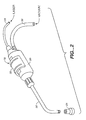
- the device 16 comprises a housing 20 adapted to be hand held by the surgeon during an operative procedure, a J-shaped neck member 22 attached to the housing and an interchangeable distal head member 24 having a hollow piercing tip 25 (See Fig. 3A).
- An optical fiber bundle 26 whose proximal end is connected to the laser source 28 extends through the housing and through the neck member to the distal end member.
- the fiber bundle 26 is connected to a movable shuttle 30 (Fig. 3) which extends outside the housing and is connected to a thumb actuated control member 32.
- the vacuum line 36 extending from the vacuum source 37 such as a conventional hospital vacuum type canister device is connected to a barbed inlet 38 in the housing 20. This inlet communicates with an air passage 39 around the fiber bundle that extends to distal head member 24.
- a suction is provided at the distal head member 24 of the device 16 which performs two vital functions. First of all, the suction force draws the epicardium tissue firmly against the contacting face of the distal head member 24 so that a relatively small opening can be made in the epicardium muscle fibers to allow the distal end of the fiber bundle 26 to penetrate and engage the myocardium.
- the housing 20 which may be molded from a suitable plastic material, has an enlarged central cavity 40 to accommodate the shuttle 30.
- the latter has a cylindrical portion which surrounds and is firmly attached to the fiber bundle 26. Attached to the cylindrical portion is a web portion 42 which extends through an axial slot 44 in the housing.
- the web portion is connected to the control member 32 on the outside of the housing 20 which preferably has an arcuate configuration in cross section with a pair of external, transverse ridge portions 46 that facilitate easy thumb control by the surgeon.
- the barbed inlet 38 for the vacuum line 36 which communicates with the air passage 39 to the distal end member 24.
- An internal rubber disk 48 is provided within the housing to seal the air passage from the central cavity 40. The disk surrounds the fiber bundle and is held in place along its periphery by an annular groove 49.
- the housing tapers to a threaded end portion 50 having a tapered end surface 52 for receiving a flared end 54 of the neck member 22.
- a jam nut 56 around the neck member can be tightened on the threaded end portion 50 to secure the neck member to the housing 20.
- the jam nut 56 is preferably provided with a radially extending, integral fin or projection 57 which provides a means for easily turning the jam nut to loosen or tighten it. This enables the surgeon to quickly adjust the axial orientation of the J-shaped neck member 22 and thus the position of the distal head member 24 relative to the housing 20.
- the proximal end of the optical fiber bundle 26 is connected to the source or generator 28 of laser energy which is preferably a Holmium laser that operates at a wave length in the range of 1.8 to 2.2 microns and a pulse frequency in the range of 2 - 25 Hertz.
- laser energy is preferably a Holmium laser that operates at a wave length in the range of 1.8 to 2.2 microns and a pulse frequency in the range of 2 - 25 Hertz.
- This type of laser is preferable because it provides high absorption efficiency, hemostosis and a moderate absorption range in myocardium tissue, and is compatible with optical fiber delivery.
- the optical fiber bundle 26 which, at its distal end, has a diameter of around 1 mm.
- the optical fiber bundle is comprised of a plurality (e.g. 37) of glass fibers 32 each having a diameter of 100 microns. These glass fibers are held together by a suitable plastic material, such a 353 ND Epoxy, and near its distal tip, the bundle is preferably surrounded by an annular tantalum marker which serves to retain the bundle in a closely packed geometric boundary surrounding the bundled fibers is a plastic protective sheath such as polypropylene having a wall thickness of 0.1 mm (.004 inches). Other fiber bundle configurations could be used within the scope of the invention.
- the neck member 22 of the device 16 is a tubular member having a uniform outside diameter (e.g. 0.120 inches) (3 mm) and inside diameter (e.g. 0.094 inches) (2.4 mm) preferably bent into an angular "J" shape within which the optical fiber bundle 26 is slidable.
- This neck portion is preferably made from a stainless steel which is heat treated to make it malleable and thus somewhat flexible. This enables the neck portion to be easily bent so that its distal end head member 24 can be positioned to accommodate the specific requirements of the surgical procedure being performed.
- this head member 24 Removably attached to the distal end of the tubular neck-is the enlarged positioning and stabilizing head member 24 for the device 16 which includes the hollow piercing tip 25 for making the initial opening in the epicardium.
- this head member 24 has an annular flange portion with a generally planar end surface 27 that is transverse and preferably perpendicular to the axis of the inner passage and the fiber bundle 26 therein.
- One or more circular ridges 29 are provided in the end surface 27 so that the head member 24 will retain its position when pressed firmly against the epicardium of the heart.
- the hollow tip member 25 preferably made of a suitable metal, e.g. stainless steel, has an inner diameter that is sufficient to accommodate the fiber bundle 26 with ample clearance so that the latter will slide freely through it. At its distal end the tip member is beveled to form a sharp anti-coring needle point 58. At its other end, the tip member has an enlarged tapered head portion 60.
- the distal head member 24 has a body portion 62 with an enlarged central bore 64 having internal threads 66 that enables it to be quickly attached to the end of the neck member.
- the head member 24 could be connected to the distal end of the neck member 22 by means of a Luer taper and lock nut combination (not shown) which is a standard connection system for tubular parts that is well known in the medical field.
- an annular conical seat 68 which supports the enlarged head portion 60 of the tip member 25.
- a coiled spring 70 is preferably provided within the central bore to contact the enlarged head of the tip member and urge it against the seat 68. However, if a level of resistance is encountered by the tip member during its initial contact with the epicardium, the spring will allow some retraction of the tip member, thereby easing the initial penetration process.
- head end member 24a is shown in Fig. 3B.
- the removable piercing tip member 25 is protected by a movable outer sleeve member 72 that functions as a shield means and has a flared portion 74 with an end surface 76 that contacts the epicardium surface.
- the outer sleeve member is co-axial with and movable relative to an inner sleeve member 78 having an enlarged inner end portion 80.
- This inner sleeve has a central bore with internal threads 82 at its inner end to facilitate its connection with the distal end of the J-shaped neck member 22. Within the bore is an annular tapered surface 84 that forms a seat for the tapered head end of the piercing tip member 25.
- annular flange portion 86 which extends radially within an elongated inner slot 88 in the outer sleeve member 72.
- annular flange 90 that extends inwardly within an extended slot 92 that is formed by the end flanges 80 and 86 of the inner sleeve 78.
- a coiled spring 94 Situated within the extended slot 92 is a coiled spring 94.
- the outer sleeve, 72 When the head end member 24a is not in use and no axial force is applied against the end surface 76, the outer sleeve, 72, urged by the spring 94 extends beyond the end of the tip member 25 and thus protects it from any inadvertent contact with any surrounding object.
- the end surface 76 of the outer sleeve When in use, as the end surface 76 of the outer sleeve is placed against the epicardium surface, it is moved rearwardly against the spring 94 so that tip member 25 can proceed to pierce the epicardium membrane in the desired manner.
- the length of the tip member 25 is such that, in the embodiment of Fig. 3A, its tapered end normally extends around 5 mm (0.2 inches) beyond the contacting surface 27 of the head member 24.
- the tip member when the outer sleeve 72 is retracted against the spring 94, the tip member can project the same distance so that it will penetrate well through the epicardium in actual use.
- tip members of varying lengths may be used interchangeably by the surgeon to accommodate different conditions in accordance with the invention.
- Fig. 1 The use of the device 16 in a Transmyocardial Revascularization (TMR) procedure according to the invention is illustrated in Fig. 1 and in greater detail in Figs. 6-9. After the surgeon makes an opening in the patient's chest to expose the left ventricle outer wall of the heart, the device 16, connected to its laser source is held by the surgeon.
- TMR Transmyocardial Revascularization
- the device 16 is maneuvered so that its head end 24 is placed against the epicardium of the left ventricle. (Fig. 6)
- the annular end face 27 of the head end member 24 serves as a stop as it is pressed against the outer surface of patient's heart.
- the piercing tip member 25 first penetrates the tougher outer epicardium layer of the heart muscle while the distal end of the fiber bundle 26 is just inside the piercing member.
- the spring 70 provides a cushioning effect as the piercing member first engages the epicardium surface.
- the epicardium is pierced or penetrated mechanically but is not subjected to laser energy.
- the piercing tip member 25 penetrates through the epicardium with only a minimal damage to tissue and while protecting the distal end of the fiber bundle 26.
- the fiber bundle 26 is retracted by the control knob 50 and the piercing member 25 is removed.
- the opening caused by the piercing member normally closes due to the resiliency of the muscle fibers in the epicardium so that there is no bleeding or only minimal bleeding on the outer surface of the heart.
- the present invention provides an improved device for performing TMR procedures that affords versatility by virtue of its removable, replaceable distal tip members 25 and which enables the formation of effective channels for revascularization that will normally close at the epicardium membrane to minimize post-operative bleeding.
Landscapes
- Health & Medical Sciences (AREA)
- Surgery (AREA)
- Physics & Mathematics (AREA)
- Life Sciences & Earth Sciences (AREA)
- Engineering & Computer Science (AREA)
- Medical Informatics (AREA)
- Nuclear Medicine, Radiotherapy & Molecular Imaging (AREA)
- Electromagnetism (AREA)
- Optics & Photonics (AREA)
- Biomedical Technology (AREA)
- Heart & Thoracic Surgery (AREA)
- Otolaryngology (AREA)
- Molecular Biology (AREA)
- Animal Behavior & Ethology (AREA)
- General Health & Medical Sciences (AREA)
- Public Health (AREA)
- Veterinary Medicine (AREA)
- Laser Surgery Devices (AREA)
- Radiation-Therapy Devices (AREA)
Claims (13)
- Chirurgische Vorrichtung (16) zur Durchführung eines transmyokardialen Revaskularisierungsverfahrens am Herz eines Patienten, wobei die Vorrichtung umfasst:einen Griffabschnitt (20),einen röhrenförmigen Halsabschnitt (22), der mit dem Griffabschnitt (20) verbunden ist;ein abnehmbares Kopfelement (24) am distalen Ende des Halsabschnitts (22) mit einer Durchgangsbohrung (64);Durchstechmittel (25), die innerhalb des Kopfelements (24) gehalten werden und sich bei der Verwendung durch die Bohrung (64) nach außen erstrecken, um eine erste Öffnung in der Epikardmembran des Herzes auszubilden; dadurch gekennzeichnet, dass das Kopfelement (24) eine Endfläche (27) aufweist, in die sich die Durchgangsbohrung (64) öffnet, wobei die Endfläche dazu ausgebildet ist, an der Außenfläche eines behandelten Herzes anzugreifen; und dadurch, dass die Vorrichtung weiters umfasst:ein Lichtleitfasermittel (26) mit einem proximalen Ende, das an eine Laserenergiequelle angeschlossen werden kann;wobei sich das Fasermittel (26) so durch den Griffabschnitt (20) und in den Halsabschnitt (22) erstreckt, dass sich sein distales Ende innerhalb des Kopfelements (24) befindet;Steuermittel (30, 32) am Griffabschnitt (20) zum Eingriff mit dem Fasermittel (26), um es axial darin zu bewegen und dadurch sein distales Ende durch die Bohrung (64) und über das Kopfelement (24) hinaus zu bewegen; wodurch die vom Durchstechmittel (25) gebildete erste Öffnung dazu dient, das Hindurchgelangen des Fasermittels (26) zu erleichtern, so dass Laserenergie von seinem distalen Ende eingesetzt werden kann, um im Myocard des Herzes des Patienten einen Kanal auszubilden.
- Chirurgische Vorrichtung nach Anspruch 1, die Mittel (37) umfasst, die mit dem Griffabschnitt (2) verbunden sind, um an einer Öffnung am Kopfelement für Absaugung zu sorgen.
- Chirurgische Vorrichtung nach Anspruch 2, worin das Mittel zum Absaugen ein röhrenförmiges Mittel (36) umfasst, das sich von einer Vakuumquelle (37) aus erstreckt und an den Griffabschnitt (20) angeschlossen ist, um mit dem Kopfelement (24) zu kommunizieren, um das Absaugen am Epikard zu bewirken.
- Chirurgische Vorrichtung nach einem der vorangegangenen Ansprüche, worin das Kopfelement (24) ein ringförmiges Element, das einen Flanschabschnitt (86) mit einer Querfläche aufweist, die die Endfläche (27) zum Angreifen am Epikard des Herzes des Patienten bildet, einen Körperabschnitt (62) mit einer Mittelbohrung (64) und einen ringförmigen Sitzvorsprung (68) in der Bohrung (64) umfasst, der einen Abschnitt der Bohrung mit verringertem Durchmesser bildet.
- Chirurgische Vorrichtung nach Anspruch 4, worin das Durchstechmittel umfasst:ein röhrenförmiges Durchstechelement (25), das im Körperabschnitt (62) des Kopfelements (24) gehalten wird, wobei sich das Element (25) durch die Öffnung erstreckt und einen verjüngten Spitzenabschnitt (58) aufweist, wobei das Durchstechelement eine Bohrung aufweist, die groß genug ist, um Gleitbewegung des Fasermittels (26) darin zuzulassen.
- Chirurgische Vorrichtung nach Anspruch 5, worin
das Kopfelement (24a) einen axial beweglichen Sicherheitsschild (72) umfasst, der sich um das Durchstechelement (25) erstreckt. - Chirurgische Vorrichtung nach Anspruch 4, umfassend ein Eindringkraft-Abfederungsmittel (70) in der Mittelbohrung (64) des Kopfelements (249, das mit dem Durchstechelement (25) axial ausgerichtet ist und sich in Eingriff damit befindet.
- Chirurgische Vorrichtung nach Anspruch 7, worin das Eindringkraft-Abfederungsmittel eine Schraubenfeder (70) im Kopfelement umfasst, die sich mit dem Durchstechelement in Eingriff befindet und damit ausgerichtet ist.
- Chirurgische Vorrichtung nach Anspruch 5, worin sich der verjüngte Spitzenabschnitt etwa 0,20 Zoll (5 mm) über die Querfläche des Kopfelements hinaus erstreckt.
- Chirurgische Vorrichtung nach Anspruch 4, worin das röhrenförmige Durchstechelement (25) ein vergrößertes ringförmiges Kopfelement (60) aufweist, dessen Durchmesser größer als jener des Bohrungsabschnitts mit verringertem Durchmesser, aber kleiner als jener der Mittelbohrung fern vom Sitzvorsprung (68) ist.
- Chirurgische Vorrichtung nach Anspruch 5, worin sich das Kopfelement (24) im Gewindeeingriff am röhrenförmigen Halsabschnitt (22) befindet, so dass es entfernt werden kann, um das Auswechseln des Durchstechelements (25) zu erleichtern.
- Chirurgische Vorrichtung nach einem der vorangegangenen Ansprüche, umfassend Mittel (56, 57) zum Einstellen der Rotationsausrichtung des Halsabschnitts (22) und somit der Position des Kopfelements (24) in Bezug auf das Steuermittel (30, 32).
- Chirurgische Vorrichtung nach Anspruch 12, worin das Einstellmittel eine Gegenmutter (56) am Halsabschnitt (22), die am Griffabschnitt (20) befestigt ist, und einen Vorsprung (57) umfasst, der sich von der Gegenmutter aus erstreckt, um das manuelle Drehen zu erleichtern.
Applications Claiming Priority (2)
| Application Number | Priority Date | Filing Date | Title |
|---|---|---|---|
| US628849 | 1996-04-05 | ||
| US08/628,849 US5738680A (en) | 1996-04-05 | 1996-04-05 | Laser device with piercing tip for transmyocardial revascularization procedures |
Publications (2)
| Publication Number | Publication Date |
|---|---|
| EP0801928A1 EP0801928A1 (de) | 1997-10-22 |
| EP0801928B1 true EP0801928B1 (de) | 2002-07-10 |
Family
ID=24520560
Family Applications (1)
| Application Number | Title | Priority Date | Filing Date |
|---|---|---|---|
| EP97302257A Expired - Lifetime EP0801928B1 (de) | 1996-04-05 | 1997-04-02 | Lasergerät mit scharfer Spitze zur transmyokardialen Revaskularisation |
Country Status (6)
| Country | Link |
|---|---|
| US (1) | US5738680A (de) |
| EP (1) | EP0801928B1 (de) |
| JP (1) | JPH1024046A (de) |
| AU (1) | AU1668697A (de) |
| CA (1) | CA2201538A1 (de) |
| DE (1) | DE69713830T2 (de) |
Cited By (3)
| Publication number | Priority date | Publication date | Assignee | Title |
|---|---|---|---|---|
| US6881199B2 (en) | 1998-09-10 | 2005-04-19 | Percardia, Inc. | Left ventricular conduit with blood vessel graft |
| US6926690B2 (en) | 1998-09-10 | 2005-08-09 | Percardia, Inc. | Transmyocardial shunt and its attachment mechanism, for left ventricular revascularization |
| US7011095B2 (en) | 1998-09-10 | 2006-03-14 | Percardia, Inc. | Valve designs for left ventricular conduits |
Families Citing this family (69)
| Publication number | Priority date | Publication date | Assignee | Title |
|---|---|---|---|---|
| US6152918A (en) * | 1996-04-05 | 2000-11-28 | Eclipse Surgical Technologies, Inc. | Laser device with auto-piercing tip for myocardial revascularization procedures |
| US5766164A (en) * | 1996-07-03 | 1998-06-16 | Eclipse Surgical Technologies, Inc. | Contiguous, branched transmyocardial revascularization (TMR) channel, method and device |
| US5662124A (en) * | 1996-06-19 | 1997-09-02 | Wilk Patent Development Corp. | Coronary artery by-pass method |
| US5755682A (en) | 1996-08-13 | 1998-05-26 | Heartstent Corporation | Method and apparatus for performing coronary artery bypass surgery |
| US5899915A (en) * | 1996-12-02 | 1999-05-04 | Angiotrax, Inc. | Apparatus and method for intraoperatively performing surgery |
| US5947989A (en) * | 1996-12-12 | 1999-09-07 | United States Surgical Corporation | Method and apparatus for transmyocardial revascularization |
| US5913853A (en) * | 1997-01-30 | 1999-06-22 | Cardiodyne, Inc. | Laser energy device and procedure for forming a channel within tissue |
| CA2297295A1 (en) * | 1997-07-22 | 1999-02-04 | Thomas J. Pacala | Apparatus and method for transmyocardial revascularization by laser ablation |
| US6162214A (en) * | 1997-10-30 | 2000-12-19 | Eclipse Surgical Technologies, Inc. | Corning device for myocardial revascularization |
| US6056743A (en) | 1997-11-04 | 2000-05-02 | Scimed Life Systems, Inc. | Percutaneous myocardial revascularization device and method |
| US6200311B1 (en) | 1998-01-20 | 2001-03-13 | Eclipse Surgical Technologies, Inc. | Minimally invasive TMR device |
| US6015405A (en) * | 1998-01-20 | 2000-01-18 | Tricardia, L.L.C. | Device for forming holes in tissue |
| US5997531A (en) * | 1998-01-29 | 1999-12-07 | Cardiodyne, Inc. | User actuated laser energy device and procedure for forming a channel within tissue |
| US6120498A (en) * | 1998-03-05 | 2000-09-19 | Jani; Mahendra G. | Aspirating handpieces for laser surgical operations |
| US6561998B1 (en) * | 1998-04-07 | 2003-05-13 | Transvascular, Inc. | Transluminal devices, systems and methods for enlarging interstitial penetration tracts |
| US6135996A (en) * | 1998-04-17 | 2000-10-24 | Baxter International, Inc. | Controlled advancement lasing device |
| EP1089785A1 (de) | 1998-06-22 | 2001-04-11 | Neovasys, Inc. | Verfahren, implantat und abgabesystem zur steigerung der blutströmung in geweben |
| US6171251B1 (en) | 1998-07-14 | 2001-01-09 | Eclipse Surgical Technologies, Inc. | Method and apparatus for optimizing direct vessel implants for myocardial revascularization |
| JP2003524444A (ja) | 1998-09-10 | 2003-08-19 | パーカーディア,インコーポレイティド | Tmrシャント |
| US6290728B1 (en) | 1998-09-10 | 2001-09-18 | Percardia, Inc. | Designs for left ventricular conduit |
| WO2000019920A1 (en) * | 1998-10-06 | 2000-04-13 | Edwards Lifesciences Corporation | Laser handpiece for performing transmyocardial revascularization |
| US6409697B2 (en) | 1999-05-04 | 2002-06-25 | Heartstent Corporation | Transmyocardial implant with forward flow bias |
| WO2001003598A1 (en) * | 1999-07-08 | 2001-01-18 | Hutchinson Technology Incorporated | Naso-gastric reflectance spectroscopy probe |
| US7033372B1 (en) | 1999-08-04 | 2006-04-25 | Percardia, Inc. | Corkscrew reinforced left ventricle to coronary artery channel |
| US6638237B1 (en) | 1999-08-04 | 2003-10-28 | Percardia, Inc. | Left ventricular conduits and methods for delivery |
| EP1844723B1 (de) | 2000-02-03 | 2011-09-14 | Baylor College Of Medicine | Intraossalnervablationssystem |
| US6854467B2 (en) | 2000-05-04 | 2005-02-15 | Percardia, Inc. | Methods and devices for delivering a ventricular stent |
| US6921413B2 (en) * | 2000-08-16 | 2005-07-26 | Vanderbilt University | Methods and devices for optical stimulation of neural tissues |
| US6976990B2 (en) | 2001-01-25 | 2005-12-20 | Percardia, Inc. | Intravascular ventriculocoronary bypass via a septal passageway |
| US7008397B2 (en) | 2002-02-13 | 2006-03-07 | Percardia, Inc. | Cardiac implant and methods |
| DE10239950B3 (de) * | 2002-08-30 | 2004-02-26 | Trumpf Medizin Systeme Gmbh + Co. Kg | Applikationskatheter für Laserlicht |
| US7326219B2 (en) | 2002-09-09 | 2008-02-05 | Wilk Patent Development | Device for placing transmyocardial implant |
| US8808284B2 (en) | 2008-09-26 | 2014-08-19 | Relievant Medsystems, Inc. | Systems for navigating an instrument through bone |
| US8361067B2 (en) | 2002-09-30 | 2013-01-29 | Relievant Medsystems, Inc. | Methods of therapeutically heating a vertebral body to treat back pain |
| US8613744B2 (en) | 2002-09-30 | 2013-12-24 | Relievant Medsystems, Inc. | Systems and methods for navigating an instrument through bone |
| US6907884B2 (en) | 2002-09-30 | 2005-06-21 | Depay Acromed, Inc. | Method of straddling an intraosseous nerve |
| US7258690B2 (en) | 2003-03-28 | 2007-08-21 | Relievant Medsystems, Inc. | Windowed thermal ablation probe |
| DE102005003632A1 (de) | 2005-01-20 | 2006-08-17 | Fraunhofer-Gesellschaft zur Förderung der angewandten Forschung e.V. | Katheter für die transvaskuläre Implantation von Herzklappenprothesen |
| US8801764B2 (en) * | 2005-05-05 | 2014-08-12 | Biolitec Pharma Marketing Ltd | Cosmetic laser treatment device and method for localized lipodystrophies and flaccidity |
| ATE517584T1 (de) * | 2006-12-05 | 2011-08-15 | Elesta S R L | Ein satz optischer fasern zur perkutanen ablativen behandlung |
| US7896915B2 (en) | 2007-04-13 | 2011-03-01 | Jenavalve Technology, Inc. | Medical device for treating a heart valve insufficiency |
| US7846123B2 (en) | 2007-04-24 | 2010-12-07 | Emory University | Conduit device and system for implanting a conduit device in a tissue wall |
| US9044318B2 (en) | 2008-02-26 | 2015-06-02 | Jenavalve Technology Gmbh | Stent for the positioning and anchoring of a valvular prosthesis |
| WO2011104269A1 (en) | 2008-02-26 | 2011-09-01 | Jenavalve Technology Inc. | Stent for the positioning and anchoring of a valvular prosthesis in an implantation site in the heart of a patient |
| US20090312752A1 (en) * | 2008-06-11 | 2009-12-17 | Zoran Djordjevich | Medical Laser Vacuum Evacuator |
| US10028753B2 (en) | 2008-09-26 | 2018-07-24 | Relievant Medsystems, Inc. | Spine treatment kits |
| JP5688022B2 (ja) | 2008-09-26 | 2015-03-25 | リリーバント メドシステムズ、インコーポレイテッド | 骨の内部を通って器具を誘導するためのシステムおよび方法 |
| US10856978B2 (en) | 2010-05-20 | 2020-12-08 | Jenavalve Technology, Inc. | Catheter system |
| CA2799459A1 (en) | 2010-05-25 | 2011-12-01 | Jenavalve Technology Inc. | Prosthetic heart valve and transcatheter delivered endoprosthesis comprising a prosthetic heart valve and a stent |
| AU2012211082B2 (en) | 2011-01-28 | 2015-11-05 | Apica Cardiovascular Limited | Systems for sealing a tissue wall puncture |
| AU2012212215B2 (en) | 2011-02-01 | 2015-07-30 | Emory University | Systems for implanting and using a conduit within a tissue wall |
| US10390877B2 (en) | 2011-12-30 | 2019-08-27 | Relievant Medsystems, Inc. | Systems and methods for treating back pain |
| US10588691B2 (en) | 2012-09-12 | 2020-03-17 | Relievant Medsystems, Inc. | Radiofrequency ablation of tissue within a vertebral body |
| AU2013337680B2 (en) | 2012-11-05 | 2019-04-18 | Relievant Medsystems, Inc. | Systems and methods for creating curved paths through bone and modulating nerves within the bone |
| JP5973882B2 (ja) * | 2012-11-13 | 2016-08-23 | オリンパス株式会社 | 医療デバイス |
| WO2014117087A1 (en) * | 2013-01-25 | 2014-07-31 | Apica Cardiovascular Limited | Systems and methods for percutaneous access, stabilization and closure of organs |
| WO2014144085A1 (en) | 2013-03-15 | 2014-09-18 | Apk Advanced Medical Technologies, Inc. | Devices, systems, and methods for implanting and using a connnector in a tissue wall |
| US9724151B2 (en) | 2013-08-08 | 2017-08-08 | Relievant Medsystems, Inc. | Modulating nerves within bone using bone fasteners |
| CN105491978A (zh) | 2013-08-30 | 2016-04-13 | 耶拿阀门科技股份有限公司 | 用于假体瓣膜的径向可折叠框架及其制造方法 |
| EP3270825B1 (de) | 2015-03-20 | 2020-04-22 | JenaValve Technology, Inc. | Herzklappenprothesenzuführsystem |
| EP3632378B1 (de) | 2015-05-01 | 2024-05-29 | JenaValve Technology, Inc. | Vorrichtung mit reduzierter herzschrittmacherrate bei herzklappenersatz |
| US11065138B2 (en) | 2016-05-13 | 2021-07-20 | Jenavalve Technology, Inc. | Heart valve prosthesis delivery system and method for delivery of heart valve prosthesis with introducer sheath and loading system |
| CN110392557A (zh) | 2017-01-27 | 2019-10-29 | 耶拿阀门科技股份有限公司 | 心脏瓣膜模拟 |
| WO2021050767A1 (en) | 2019-09-12 | 2021-03-18 | Relievant Medsystems, Inc. | Systems and methods for tissue modulation |
| AU2021306313A1 (en) | 2020-07-10 | 2023-03-02 | Relievant Medsystems, Inc. | Vertebral denervation in conjunction with vertebral fusion |
| US12082876B1 (en) | 2020-09-28 | 2024-09-10 | Relievant Medsystems, Inc. | Introducer drill |
| EP4268150A4 (de) | 2020-12-22 | 2024-12-18 | Relievant Medsystems, Inc. | Vorhersage von kandidaten für die spinale neuromodulation |
| US12433668B1 (en) | 2021-11-08 | 2025-10-07 | Relievant Medsystems, Inc. | Impedance stoppage mitigation during radiofrequency tissue ablation procedures |
| US12171658B2 (en) | 2022-11-09 | 2024-12-24 | Jenavalve Technology, Inc. | Catheter system for sequential deployment of an expandable implant |
Family Cites Families (7)
| Publication number | Priority date | Publication date | Assignee | Title |
|---|---|---|---|---|
| US4658817A (en) * | 1985-04-01 | 1987-04-21 | Children's Hospital Medical Center | Method and apparatus for transmyocardial revascularization using a laser |
| US4846171A (en) * | 1986-10-06 | 1989-07-11 | Gv Medical, Inc. | Laser catheter adjustable control apparatus |
| DE3911796A1 (de) * | 1989-04-11 | 1990-10-18 | Messerschmitt Boelkow Blohm | Myokardsonde |
| US5380316A (en) * | 1990-12-18 | 1995-01-10 | Advanced Cardiovascular Systems, Inc. | Method for intra-operative myocardial device revascularization |
| NZ272209A (en) * | 1991-05-01 | 2001-02-23 | Univ Columbia | Myocardial revascularisation of the heart by a laser |
| WO1994014383A1 (en) * | 1992-12-22 | 1994-07-07 | Laser Engineering, Inc. | Handpiece for transmyocardial vascularization heart-synchronized pulsed laser system |
| DK145593A (da) * | 1993-12-23 | 1995-06-24 | Joergen A Rygaard | Kirurgisk dobbelt-instrument til udførelse af forbindelse mlm. arterier (end-to-side anastomose) |
-
1996
- 1996-04-05 US US08/628,849 patent/US5738680A/en not_active Expired - Fee Related
-
1997
- 1997-04-02 EP EP97302257A patent/EP0801928B1/de not_active Expired - Lifetime
- 1997-04-02 CA CA002201538A patent/CA2201538A1/en not_active Abandoned
- 1997-04-02 DE DE69713830T patent/DE69713830T2/de not_active Expired - Fee Related
- 1997-04-02 AU AU16686/97A patent/AU1668697A/en not_active Abandoned
- 1997-04-07 JP JP9088506A patent/JPH1024046A/ja active Pending
Cited By (3)
| Publication number | Priority date | Publication date | Assignee | Title |
|---|---|---|---|---|
| US6881199B2 (en) | 1998-09-10 | 2005-04-19 | Percardia, Inc. | Left ventricular conduit with blood vessel graft |
| US6926690B2 (en) | 1998-09-10 | 2005-08-09 | Percardia, Inc. | Transmyocardial shunt and its attachment mechanism, for left ventricular revascularization |
| US7011095B2 (en) | 1998-09-10 | 2006-03-14 | Percardia, Inc. | Valve designs for left ventricular conduits |
Also Published As
| Publication number | Publication date |
|---|---|
| US5738680A (en) | 1998-04-14 |
| DE69713830D1 (de) | 2002-08-14 |
| DE69713830T2 (de) | 2003-03-13 |
| CA2201538A1 (en) | 1997-10-05 |
| JPH1024046A (ja) | 1998-01-27 |
| EP0801928A1 (de) | 1997-10-22 |
| AU1668697A (en) | 1997-10-09 |
Similar Documents
| Publication | Publication Date | Title |
|---|---|---|
| US5738680A (en) | Laser device with piercing tip for transmyocardial revascularization procedures | |
| US5782823A (en) | Laser device for transmyocardial revascularization procedures including means for enabling a formation of a pilot hole in the epicardium | |
| EP0792624B1 (de) | Chirurgisches Gerät zur transmyokardialen Revaskularisation | |
| US5703985A (en) | Optical fiber device and method for laser surgery procedures | |
| US6152918A (en) | Laser device with auto-piercing tip for myocardial revascularization procedures | |
| US6011889A (en) | Piercing point optical fiber device for laser surgery procedures | |
| US6019756A (en) | Laser device for transmyocardial revascularization procedures | |
| US5389096A (en) | System and method for percutaneous myocardial revascularization | |
| US5380316A (en) | Method for intra-operative myocardial device revascularization | |
| US5840075A (en) | Dual laser device for transmyocardial revascularization procedures | |
| US5885272A (en) | System and method for percutaneous myocardial revascularization | |
| US7137395B2 (en) | Circumferential pulmonary vein ablation using a laser and fiberoptic balloon catheter | |
| US6156029A (en) | Selective treatment of endocardial/myocardial boundary | |
| US6620153B2 (en) | Intraoperative myocardial device and stimulation procedure | |
| US6200311B1 (en) | Minimally invasive TMR device | |
| US7776025B2 (en) | Method for providing medicament to tissue | |
| JP2001509715A (ja) | 組織内に導管を形成するためのレーザー・エネルギー装置と処置方法 | |
| EP1018961A1 (de) | Transmyokardiale wiedergefässbildung mit radiofrequenzenergie | |
| US5911729A (en) | Electrocautery coring using solid needle | |
| EP1021737B1 (de) | Vorrichtung zur gewebeablation | |
| JP2001510701A (ja) | レーザーアブレーションによる経心筋脈管再生のための装置および方法 | |
| AU9409698A (en) | Selective treatment of endocardial/myocardial boundary |
Legal Events
| Date | Code | Title | Description |
|---|---|---|---|
| PUAI | Public reference made under article 153(3) epc to a published international application that has entered the european phase |
Free format text: ORIGINAL CODE: 0009012 |
|
| AK | Designated contracting states |
Kind code of ref document: A1 Designated state(s): BE DE FR GB IT NL |
|
| 17P | Request for examination filed |
Effective date: 19980206 |
|
| 17Q | First examination report despatched |
Effective date: 19990812 |
|
| RAP1 | Party data changed (applicant data changed or rights of an application transferred) |
Owner name: ECLIPSE SURGICAL TECHNOLOGIES, INC. |
|
| GRAG | Despatch of communication of intention to grant |
Free format text: ORIGINAL CODE: EPIDOS AGRA |
|
| GRAG | Despatch of communication of intention to grant |
Free format text: ORIGINAL CODE: EPIDOS AGRA |
|
| GRAH | Despatch of communication of intention to grant a patent |
Free format text: ORIGINAL CODE: EPIDOS IGRA |
|
| GRAH | Despatch of communication of intention to grant a patent |
Free format text: ORIGINAL CODE: EPIDOS IGRA |
|
| GRAA | (expected) grant |
Free format text: ORIGINAL CODE: 0009210 |
|
| AK | Designated contracting states |
Kind code of ref document: B1 Designated state(s): BE DE FR GB IT NL |
|
| REG | Reference to a national code |
Ref country code: GB Ref legal event code: FG4D |
|
| RIC1 | Information provided on ipc code assigned before grant |
Free format text: 7A 61B 18/00 A |
|
| REF | Corresponds to: |
Ref document number: 69713830 Country of ref document: DE Date of ref document: 20020814 |
|
| RAP2 | Party data changed (patent owner data changed or rights of a patent transferred) |
Owner name: CARDIOGENESIS CORPORATION |
|
| NLT2 | Nl: modifications (of names), taken from the european patent patent bulletin |
Owner name: CARDIOGENESIS CORPORATION |
|
| ET | Fr: translation filed | ||
| PG25 | Lapsed in a contracting state [announced via postgrant information from national office to epo] |
Ref country code: GB Free format text: LAPSE BECAUSE OF NON-PAYMENT OF DUE FEES Effective date: 20030402 |
|
| PG25 | Lapsed in a contracting state [announced via postgrant information from national office to epo] |
Ref country code: BE Free format text: LAPSE BECAUSE OF NON-PAYMENT OF DUE FEES Effective date: 20030430 |
|
| PLBE | No opposition filed within time limit |
Free format text: ORIGINAL CODE: 0009261 |
|
| STAA | Information on the status of an ep patent application or granted ep patent |
Free format text: STATUS: NO OPPOSITION FILED WITHIN TIME LIMIT |
|
| 26N | No opposition filed |
Effective date: 20030411 |
|
| BERE | Be: lapsed |
Owner name: *CARDIOGENESIS CORP. Effective date: 20030430 |
|
| PG25 | Lapsed in a contracting state [announced via postgrant information from national office to epo] |
Ref country code: NL Free format text: LAPSE BECAUSE OF NON-PAYMENT OF DUE FEES Effective date: 20031101 Ref country code: DE Free format text: LAPSE BECAUSE OF NON-PAYMENT OF DUE FEES Effective date: 20031101 |
|
| GBPC | Gb: european patent ceased through non-payment of renewal fee |
Effective date: 20030402 |
|
| NLV4 | Nl: lapsed or anulled due to non-payment of the annual fee |
Effective date: 20031101 |
|
| PG25 | Lapsed in a contracting state [announced via postgrant information from national office to epo] |
Ref country code: FR Free format text: LAPSE BECAUSE OF NON-PAYMENT OF DUE FEES Effective date: 20031231 |
|
| REG | Reference to a national code |
Ref country code: FR Ref legal event code: ST |
|
| PG25 | Lapsed in a contracting state [announced via postgrant information from national office to epo] |
Ref country code: IT Free format text: LAPSE BECAUSE OF NON-PAYMENT OF DUE FEES Effective date: 20050402 |