EP0801938B1 - Vorrichtung zur Wärmebehandlung - Google Patents
Vorrichtung zur Wärmebehandlung Download PDFInfo
- Publication number
- EP0801938B1 EP0801938B1 EP97106282A EP97106282A EP0801938B1 EP 0801938 B1 EP0801938 B1 EP 0801938B1 EP 97106282 A EP97106282 A EP 97106282A EP 97106282 A EP97106282 A EP 97106282A EP 0801938 B1 EP0801938 B1 EP 0801938B1
- Authority
- EP
- European Patent Office
- Prior art keywords
- thermal
- thermal treatment
- treatment apparatus
- tubular
- catheter
- Prior art date
- Legal status (The legal status is an assumption and is not a legal conclusion. Google has not performed a legal analysis and makes no representation as to the accuracy of the status listed.)
- Expired - Lifetime
Links
Images



Classifications
-
- A—HUMAN NECESSITIES
- A61—MEDICAL OR VETERINARY SCIENCE; HYGIENE
- A61F—FILTERS IMPLANTABLE INTO BLOOD VESSELS; PROSTHESES; DEVICES PROVIDING PATENCY TO, OR PREVENTING COLLAPSING OF, TUBULAR STRUCTURES OF THE BODY, e.g. STENTS; ORTHOPAEDIC, NURSING OR CONTRACEPTIVE DEVICES; FOMENTATION; TREATMENT OR PROTECTION OF EYES OR EARS; BANDAGES, DRESSINGS OR ABSORBENT PADS; FIRST-AID KITS
- A61F7/00—Heating or cooling appliances for medical or therapeutic treatment of the human body
- A61F7/12—Devices for heating or cooling internal body cavities
-
- A—HUMAN NECESSITIES
- A61—MEDICAL OR VETERINARY SCIENCE; HYGIENE
- A61F—FILTERS IMPLANTABLE INTO BLOOD VESSELS; PROSTHESES; DEVICES PROVIDING PATENCY TO, OR PREVENTING COLLAPSING OF, TUBULAR STRUCTURES OF THE BODY, e.g. STENTS; ORTHOPAEDIC, NURSING OR CONTRACEPTIVE DEVICES; FOMENTATION; TREATMENT OR PROTECTION OF EYES OR EARS; BANDAGES, DRESSINGS OR ABSORBENT PADS; FIRST-AID KITS
- A61F7/00—Heating or cooling appliances for medical or therapeutic treatment of the human body
- A61F2007/0054—Heating or cooling appliances for medical or therapeutic treatment of the human body with a closed fluid circuit, e.g. hot water
-
- A—HUMAN NECESSITIES
- A61—MEDICAL OR VETERINARY SCIENCE; HYGIENE
- A61F—FILTERS IMPLANTABLE INTO BLOOD VESSELS; PROSTHESES; DEVICES PROVIDING PATENCY TO, OR PREVENTING COLLAPSING OF, TUBULAR STRUCTURES OF THE BODY, e.g. STENTS; ORTHOPAEDIC, NURSING OR CONTRACEPTIVE DEVICES; FOMENTATION; TREATMENT OR PROTECTION OF EYES OR EARS; BANDAGES, DRESSINGS OR ABSORBENT PADS; FIRST-AID KITS
- A61F7/00—Heating or cooling appliances for medical or therapeutic treatment of the human body
- A61F7/02—Compresses or poultices for effecting heating or cooling
- A61F2007/0295—Compresses or poultices for effecting heating or cooling for heating or cooling or use at more than one temperature
- A61F2007/0296—Intervals of heating alternated with intervals of cooling
Definitions
- the present invention relates to a thermal treatment apparatus which is able to provide a desired temperature to a minimal quantity of fluid circulating in a closed system of the thermal treatment apparatus.
- the thermal treatment apparatus can be used to selectively treat a targeted tissue by applying fluid-induced thermal therapy, as disclosed in US-A-5 257 977 and EP-A-0 672 401.
- Fluid induced thermal therapy is based on localized heating of a targeted tissue to a predetermined temperature by means of circulating fluid, while keeping the temperature of adjacent healthy tissues unchanged. Relative to therapy methods which use laser, microwave, radiofrequency and ultrasound to produce heat within a tissue, the fluid-induced thermotherapy allows better control of the temperature and the limits of the treated site.
- a thermal treatment apparatus may be used for selectively preserving a portion of a tissue treated by cryosurgery, by selectively heating that portion of the tissue.
- Prior art includes heating bath circulators and a heater based on a container serving as a water reservoir.
- An example is described in EP-A-0 672 401, according to which the preamble of claim 1 has been drafted.
- a thermal treatment apparatus for the treatment of the human body comprising a temperature-setting device for providing a predetermined temperature to a quantity of fluid circulating in a closed-loop system of the thermal treatment apparatus, configured to heat and/or cool the circulating fluid to a predetermined temperature, comprising a tubular thermal element having a body that encloses a fluid flow passage and an axial length with opposing first and second ends, said tubular thermal element having thermal conductivity and being sized and configured to allow circulating fluid to flow therethrough, wherein, in operation, said tubular thermal element body is configured to be heated and/or cooled and to transfer its thermal energy to heat and/or cool the circulating fluid to a predetermined temperature as the circulating fluid flows therethrough.
- the temperature setting device has a housing element for receiving and anchoring said tubular element therein, and for electrically connecting the tubular element to an electrical circuit; and a transformer element electrically connectable to the electrical circuit.
- the tubular element has two ends connectable to electrically and thermally insulating tubular elements.
- the housing element includes fastening elements, comprising: a connector member having a relatively good electrical conductivity, connectable to an electrical circuit; and fastening member for anchoring the tubular member between the fastening member and the connector member.
- the temperature-setting device may include a sensor for sensing the temperature of the tubular element.
- the sensor and the transformer element may be electrically connected to a controller.
- the controller may control the duty cycle of the transformer according to the temperature sensed by the sensor.
- the controller may interrupt the operation of the transformer and the electrical circuit upon over--heating of the tubular element.
- the tubular element and the insulating tubular elements may be disposable.
- the housing element comprises a thermal conducting member disposed within a bath of a cooling substance, the thermal conducting member featuring a recess for receiving the tubular element therein.
- the recess preferably defines a lowered area relative to the surface of the cooling substance, for trapping cold air.
- the recess may be used for receiving a small quantity of fluid for improving the thermal coupling between the thermal conducting member and the tubular element.
- the thermal conducting member features extensions for increasing the area of contact between the thermal conducting member and the cooling substance.
- the tubular element may alternately be placed in embodiments functioning as heaters and embodiments functioning as coolers, thereby alternately heating and cooling the fluid circulating therethrough.
- the housing element is in the form of two thermal conducting plates, each of which controllably connectable to a heating and/or cooling source such as a peltier heat pump element.
- Each of the thermal conducting plates may feature a recess, the recesses defining a tunnel for receiving the tubular element therein, preferably under pressure.
- the thermal conducting plates may alternately heat and cool the tubular element, thereby alternately heating and cooling the fluid circulating therethrough.
- the thermal treatment apparatus further comprises:(a) a catheter adapted for insertion into the human body, said catheter including a thermal treatment section for thermally treating targeted tissue in the human body by exposing targeted tissue to circulating fluid heated to a predetermined temperature that is contained in said catheter thermal treatment section; (b) the temperature-setting being in fluid communication with said catheter such that the circulating fluid flows through said tubular heating element as it travels in the circulating flow path; (c) a pump operably associated with said tubular heating element and catheter, said pump configured to drive said fluid through said circulating flow path; (d) a power source operably associated with said pump and said tubular heating element; and (e) a controller operably associated with said tubular heating element (3) and said power source, wherein, in operation, said tubular heating element body is controllably heated to thereby heat the circulating fluid traveling therethrough to a predetermined temperature.
- the thermal treatment apparatus may further include a second thermal sensor assembly for sensing the temperature of fluid circulating out of the catheter.
- the thermal treatment apparatus may include an air trapping element, for trapping air circulating in the system.
- the present invention successfully addresses the shortcomings of the presently known configurations by providing a temperature-setting device for providing a predetermined temperature to a minimal quantity of fluid circulating in a closed system.
- the present invention discloses a novel temperature-setting device which allows to alternately heat and cool a component of such closed system, the component being in the form of a tubular element having relatively good thermal conductivity, by alternately placing the component in embodiments of the device functioning as heaters and embodiments functioning as coolers.
- a technique for selectively thermally treating a targeted tissue adjacent a subject's body cavity comprises the steps of: (a) inserting into a subject's body cavity a catheter, including a thermal treating section for thermally treating said targeted tissue adjacent to the body cavity by circulating fluid of a predetermined temperature through said thermal treating section, the catheter being disposable; (b) heating fluid circulating in a closed system including the catheter, and further including: a pump for pumping fluid through the closed system; thermal sensor assemblies for sensing the temperature of fluid circulating into and out of the catheter; and a temperature-setting device for heating the fluid circulating therethrough, the temperature-setting device including: (i) a tubular element having relatively low electrical conductivity and good thermal conductivity for receiving a quantity of circulating fluid, the tubular element having two ends connectable to electrically and thermally insulating tubular elements, the tubular element and the insulating tubular elements being disposable; (ii) a housing element for receiving the tubular element, the housing element including fastening elements, including: a connector member having relatively good
- the catheter may include a proximal end formed with an inflatable thermal treating section to be located within the body cavity, and a distal end to be located externally of the body cavity; the catheter being formed with first and second passageways extending from the distal end to the inflatable thermal treating section for circulating fluid of a predetermined temperature through the inflatable thermal treating section.
- the catheter may include a proximal end formed with an inflatable anchoring section for anchoring the catheter in the body cavity, a distal end to be located externally of the body cavity, and an inflatable thermal treating section adjacent the proximal end to be located near the targeted tissue; the catheter being formed with first and second passageways extending from the distal end to the inflatable thermal treating section for circulating fluid of a predetermined temperature through the inflatable thermal treating section, and a third passageway extending from the distal end to the inflatable anchoring section for introducing unheated fluid into the inflatable anchoring section.
- the catheter may further include thermal insulation surrounding the first and second passageways from close to the distal end to close to the inflatable thermal section, the thermal insulation including a plurality of separate compartments containing a non-heated fluid, the compartments extending axially along the catheter, thereby the inflatable thermal treating section and the targeted tissue in its proximity may be heated to a desired temperature without correspondingly heating non-targeted tissues.
- the tubular element of the temperature-setting device, the insulating tubular elements and other tubular elements constituting the closed system may be disposable.
- the pump may include: (a) a housing formed with a substantially cylindrical cavity having an inner surface, the housing provided with a lid, the lid having a depending skirt removably engageable within the cylindrical cavity so as to form an inset lining around a part of the inner surface; (b) a rotor rotatably mounted within the cylindrical cavity, the rotor carrying rollers; and (c) a peristaltic tube, the peristaltic tube being disposable, such that, when the depending skirt is not engaged in the cylindrical cavity, the peristaltic tube may be easily inserted between the rollers and the inner surface and, when the depending skirt is engaged in the cylindrical cavity, the peristaltic tube is engaged between the rollers and the inset lining such that rotation of the rotor pumps fluid through the peristaltic tube.
- the thermal sensor assembly may include: a thermal sensor; a disposable metal tube connectable to the end of a passageway of the catheter to receive the fluid flowing therethrough; a metal thermal coupling member formed with a recess on one face for receiving the thermal sensor therein, a recess on the opposite face complementary to the shape of the metal tube for receiving the metal tube therein, and a relatively thin web between the two recesses; and a cover pressing the metal tube to the thermal coupling member.
- the apparatus used in the technique for selectively thermally treating a targeted tissue may further include an air trapping element for trapping air circulating in the system, the air trapping element comprising a hung container controllably connectable to the closed system, the air trapping element being disposable.
- a further technique for selectively thermally treating a targeted tissue adjacent to a subject's body cavity comprises the steps of: (a) inserting into a subject's body cavity a catheter, including a thermal treating section for thermally treating the targeted tissue adjacent the body cavity by circulating fluid of a predetermined temperature through the thermal treating section, the catheter being disposable; (b) alternately heating and cooling fluid circulating in a closed system including the catheter, and further including: a pump for pumping fluid through the closed system; thermal sensor assemblies for sensing the temperature of fluid circulating into and out of the catheter; and a temperature-setting device for alternately heating and cooling the fluid circulating therethrough, the temperature-setting device comprising: a tubular element having relatively low electrical conductivity and good thermal conductivity for receiving a quantity of circulating fluid, the tubular element having two ends connectable to electrically and thermally insulating tubular elements, the tubular element and the insulating tubular elements being disposable; a heating housing element for receiving the tubular element, the housing element detachably connectable to a heating source
- the temperature-setting device may comprise: ( a ) a tubular element having relatively low electrical conductivity and good thermal conductivity for receiving a quantity of circulating fluid, the tubular element having two ends connectable to electrically and thermally insulating tubular elements, the tubular element and the insulating tubular elements being disposable; (b) a heating housing element for receiving the tubular element, the housing element including fastening elements, including: (i) a connector member having relatively good electrical conductivity, the connector member connectable to an electrical circuit; (ii) a fastening member for anchoring the tubular element between the fastening member and the connector member; (c) a transformer element connectable to the electrical circuit, the transformer element electrically connected to the controller; and (d) a cooling housing element comprising a thermal conducting member disposed within a bath of a cooling substance, the thermal conducting member having a recess for receiving the tubular element, the recess defining a relatively lowered area for trapping cold air, the thermal conducting member featuring extensions for increasing the contact area between the
- a technique for selectively thermally treating a targeted tissue adjacent a subject's body cavity may comprise the steps of: (a) inserting into a subject's body cavity a catheter, including a thermal treating section for thermally treating the targeted tissue adjacent the body cavity by circulating fluid of a predetermined temperature through the thermal treating section, the catheter being disposable; (b) alternately heating and cooling fluid circulating in a closed system including the catheter, and further including: a pump for pumping fluid through the closed system; thermal sensor assemblies for sensing the temperature of fluid circulating into and out of the catheter; and a temperature-setting device for alternately heating and cooling the fluid circulating therethrough, the temperature-setting device comprising: (i) a tubular element having relatively good thermal conductivity for receiving a quantity of circulating fluid, the tubular element having two ends connectable to thermally insulating tubular elements, the tubular element and the insulating tubular elements being disposable; (ii) a housing element for alternately heating and cooling the tubular element, the housing element comprising two thermal conducting plates, each having
- the temperature-setting device may comprise: (a) a tubular element having relatively good thermal conductivity for receiving a quantity of circulating fluid, the tubular element having two ends connectable to thermally insulating tubular elements, the tubular element and the insulating tubular elements being disposable; (b) a housing element for alternately heating and cooling said tubular element, the housing element comprising two thermal conducting plates, each having a recess, the recesses defining a tunnel for receiving the tubular element under pressure; and (c) peltier heat pump elements detachably connectable to the thermal conducting plates, the peltier heat pump elements alternately heating and cooling the thermal conducting plates, thereby alternately heating and cooling the fluid circulating through the tubular element.
- a technique for selectively thermally treating a targeted tissue adjacent a subject's body cavity may comprise the steps of: (a) inserting into a subject's body cavity a catheter, including a thermal treating section for thermally treating the targeted tissue adjacent the body cavity by circulating fluid of a predetermined temperature through the thermal treating section, the catheter being disposable; (b) heating fluid circulating in a closed system including the catheter, and further including: a pump for pumping fluid through the closed system; thermal sensor assemblies for sensing the temperature of fluid circulating into and out of the catheter; and a temperature-setting device for heating the fluid circulating therethrough, the temperature-setting device comprising: (i) a tubular element having relatively good thermal conductivity for receiving a quantity of circulating fluid, the tubular element having two ends connectable to thermally insulating tubular elements, the tubular element and the insulating tubular elements being disposable; (ii) a housing element for heating the tubular element, the housing element comprising two thermal conducting plates, each having a recess, the recesses defining
- the catheter may include a proximal end formed with an inflatable thermal treating section to be located within the body cavity, and a distal end to be located externally of the body cavity; the catheter being formed with first and second passageways extending from the distal end to the inflatable thermal treating section for circulating fluid of a predetermined temperature through the inflatable thermal treating section.
- the catheter may include a proximal end formed with an inflatable anchoring section for anchoring the catheter in the body cavity, distal end to be located externally of the body cavity, and an inflatable thermal treating section adjacent the proximal end to be located near the targeted tissue; the catheter being formed with first and second passageways extending from the distal end to the inflatable thermal treating section for circulating fluid of a predetermined temperature through the said inflatable thermal treating section, and a third passageway extending from the distal end to the inflatable anchoring section for introducing unheated fluid into the inflatable anchoring section.
- the catheter may further include thermal insulation surrounding the first and second passageways from close to the distal end to close to the inflatable thermal section, the thermal insulation including a plurality of separate compartments containing a non-heated fluid, the compartments extending axially along the catheter, thereby the inflatable thermal treating section and the targeted tissue in its proximity may be heated to a desired temperature without correspondingly heating non-targeted tissues.
- the temperature-setting device may comprise: an electrically conducting tubular element, a housing element for receiving the tubular element; and a transformer electrically connectable to the housing element.
- the tubular element functions as a resistor and heats the fluid circulating therethrough.
- the housing element comprises a thermal conducting member disposed within a bath of a cooling substance, the thermal conducting member having a recess for receiving the tubular element.
- the tubular element may alternately be placed in a housing element functioning as a heater and a housing element functioning as a cooler, thereby alternately heating or cooling the fluid circulating therethrough.
- the thermal treatment apparatus may comprise: the temperature-setting device ; a catheter insertable into a subject's body cavity, the catheter including a thermal treating section for thermally treating a targeted tissue; a pump; thermal sensor assemblies; and an air trapping element.
- the present invention is of a thermal treatment apparatus for the treatment of the human body comprising a temperature-setting device for providing a desired temperature to a minimal quantity of fluid circulating in a closed system for selectively treating a targeted tissue by fluid-induced thermal therapy using a minimal quantity of circulating fluid and consuming minimal energy for heating (or cooling) the fluid.
- FIG. 1 illustrates a thermal treatment apparatus which uses fluid-induced thermal therapy for selectively treating a targeted tissue adjacent a subject's body cavity.
- the thermal treatment apparatus comprises a closed system, including: a temperature-setting device 4 for providing a desired temperature to a minimal quantity of fluid circulating through the system; a catheter 2 insertable into the subject's body cavity and connectable to temperature-setting device 4; a pump 6 for pumping the fluid through the system, the pump connectable to temperature-setting device 4; and preferably two thermal sensor assemblies 8 and 10 for measuring the temperature of fluid circulating into and out of catheter 2, respectively.
- the closed system further includes an air trapping element 7 for trapping air circulating in the closed system.
- the thermal treatment apparatus further includes a controller 12 for controlling the operation of temperature-setting device 4 and pump 6, preferably according to the temperature sensed by thermal sensor assemblies 8 and 10.
- a temperature-setting device includes a resistive tubular element 3 having relatively low electrical conductivity and good thermal conductivity.
- Tubular element 3 may be made, for example, of stainless steel.
- Tubular element 3 is preferably disposable.
- temperature-setting device 4 further includes a housing element (not shown) having a recess for receiving tubular element 3.
- the housing element preferably includes two fastening elements 5 for mechanically anchoring tubular element 3 in the housing element, and electrically connecting the ends of tubular element 3 to a transformer 11.
- Each of fastening elements 5 comprises two components 5a and 5b.
- Component 5a preferably includes a fastening member such as a screwing element for anchoring tubular element 3 between component 5a and component 5b.
- Component 5b has relatively good electrical conductivity for allowing electrical connection between tubular element 3 and transformer 11.
- tubular element 3 Since tubular element 3 has relatively low electrical conductivity, it functions as a resistor and converts electrical energy to heat, thereby heating the fluid circulating therethrough. This configuration allows to circulate a minimal quantity of heated fluid through the system. Preferably, the quantity of circulating fluid is about 20-50 ml.
- the voltage produced by transformer 11 is preferably very low, about 1-5 volts, in order to provide the necessary safety while using the device.
- temperature-setting device 4 further includes a temperature sensor 107 located at the housing element, for sensing the temperature of tubular element 3.
- the connection between sensor 107 and tubular element 3 is preferably established readily upon mounting of element 3 in the housing element, under pressure.
- Controller 12 may control the duty cycle of transformer 11 according to the temperature sensed by sensor 107, where the duty cycle refers to the time intervals during which transformer 11 provides electrical current or voltage to the system. Additionally, sensor 107 may function as a safety switch, so that when fluid circulation in the system is interrupted, sensor 107 heats up and consequently controller 12 preferably interrupts the operation of the overall system.
- controller 12 may control the duty cycle of transformer 11 according to the temperature sensed by thermal sensor assemblies 8 and 10.
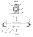
- the housing element comprises a thermal conducting member 14 disposed within a bath 13 of a cooling substance 15, such as ice.
- Thermal conducting member 14 preferably features a recess 14a for receiving tubular element 3 therein.
- Recess 14a preferably defines a lowered area relative to the surface 15a of cooling substance 15, for trapping cold air. This configuration creates a local well of cold air defined by recess 14a, for efficiently cooling tubular element 3.
- recess 14a may be used for receiving a quantity of fluid for improving the thermal coupling between thermal conducting member 14b and tubular element 3.
- thermal conducting member 14 further features extensions 14b for increasing the area of contact between thermal conducting member 14 and cooling substance 15.
- the housing element is stored under freezing conditions while not in use.
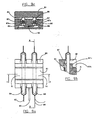
- Temperature-setting device 4 may be used to alternately heat and cool a minimal quantity of fluid circulating through the system, by alternately placing tubular element 3 in embodiments of the device functioning as heaters (e.g. the configuration shown in FIG. 1) and embodiments functioning as coolers (e.g. the configuration shown in FIGs. 2a and 2b). While using the configuration of FIGs. 2a and 2b, transformer 11 is not used.
- the housing element comprises two plates 16a and 16b, made of a material having relatively good thermal conductivity such as aluminum.
- Plates 16a and 16b are controllably connectable to heating and/or cooling sources 17 and 18, respectively.
- Heating and/or cooling sources 17 and 18 may be, for example, peltier heat pump elements.
- each of plates 16a and 16b may feature a recess, the recesses defining a tunnel for receiving tubular element 3 therein, preferably under pressure. This configuration allows better thermal coupling between thermal conducting plates 16a and 16b and tubular element 3.
- tubular element 3 is placed within the recess of plate 16b.
- Plate 16a is then placed on top of plate 16b, covering tubular element 3 so that tubular element 3 is preferably pressed within the tunnel defined by the recesses of plates 16a and 16b.
- This configuration may be used as a heater and/or cooler, according to the function (heating or cooling) performed by sources 17 and 18. While using this configuration, transformer 11 is not used.
- thermal treatment apparatus further includes a catheter 2 connectable to temperature-setting device 4 and insertable into a subject's body cavity such as urinary bladder, prostatic urethra, uterus and esophagus, for selectively treating a targeted tissue within or near such cavity.
- a catheter 2 connectable to temperature-setting device 4 and insertable into a subject's body cavity such as urinary bladder, prostatic urethra, uterus and esophagus, for selectively treating a targeted tissue within or near such cavity.
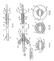
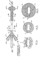
- catheter 2 preferably includes a long slender tube 20 formed with an inflatable anchoring section 21 at the proximal end for anchoring the catheter in the subject's body cavity, and thereby locating an inflatable cylindrical thermal treating section 22 near the targeted tissue to be treated.
- the length of thermal treating section 22 may preferably be adapted according to the distance between the bladder neck and the verumontanum of the particular patient.
- the distal end of catheter 23 is to be located externally of the subject's body so as to be readily accessible for inflating anchoring section 21 and thermal treating section 22.
- a limited quantity of a fluid having a predetermined temperature is circulated through inflatable thermal treating section 22 via two passageways 24a and 24b having an inlet 25 and an outlet 26 at distal end 23 of the catheter.
- a valve member 2a is connected to outlet 26 of the catheter for introducing fluid into the closed system.
- Inflatable anchoring section 21 of the catheter is preferably inflated by an amount of unheated fluid introduced via inlet 27 at distal end 23 of the catheter.
- Inlet 27 preferably communicates with anchoring section 21 via an unheated-fluid passageway 28 and an opening 29.
- the portion of the catheter from distal end 23 to inflatable thermal treating section 22 is preferably thermally insulated from the subject's untargeted tissues by means of insulating chambers 30 enclosing passageways 24a and 24b.
- One of insulating chambers 30 preferably communicates with unheated-fluid passageway 28 through which unheated air is applied to inflate anchoring section 21.
- the catheter also includes an extension 31 at the proximal end, which extension is received within the subject's body cavity.
- Extension 31 is formed with an opening 32 for draining body fluids via draining passageway 33 passing through the length of the catheter and terminating in an outlet 34 attachable to a drain.
- passageway 33 may be used for introducing a drug into the subject's body cavity.
- passageway 33 may be used for introducing a stiffening element for facilitating the insertion of the catheter to the subject's body cavity.
- Catheter 2 and valve member 2a are preferably disposable.
- catheter 2 includes only one chamber 30 for communicating with inlet 27 and passageway 28 through which unheated air is applied to inflate anchoring section 21, so that passageways 24a and 24b along slender tube 20 are not insulated.
- thermal treating section 22 may feature any geometrical shape, according to the specific geometry of the subject's body cavity. Such configuration may be used, for example, for endometrial ablation, where the geometry of thermal treating section 22 is adapted to fit the specific geometry of a subject's uterus, and insulating chambers 30 enable the use of a heating source for heating the fluid, which is completely external to the subject's body.
- anchoring section 21 is made as an integral part of thermal treating section 22, and all of chambers 30, inlet 27 and passageway 28 are missing, so that passageways 24a and 24b along slender tube 20 are not insulated.
- Inflatable thermal treating section 22 may feature any geometrical shape, according to the specific geometry of the subject's body cavity. Such configuration may be used, for example, for selectively heating a portion of a tissue treated by cryosurgery, thereby preserving that portion.
- thermal treatment apparatus further includes a pump 6 connectable to catheter 2 and temperature-setting device 4.
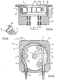
- Pump 6 is preferably a peristaltic pump, and includes a housing 60 formed with a cylindrical cavity 61. Disposed within cylindrical cavity 61 is a rotor 62 connected by a drive shaft 63 to a gear motor (not shown) and including a pair of spaced discs 64a, 64b rotatably mounting between them a plurality (3) of rollers 65 within cavity 61. Also located within cylindrical cavity 61 is a peristaltic tube 66 which is engageable by roller 65 for pumping the fluid through the tube during the rotation of rotor 62. Assuming rotor 62 is rotated counter-clockwise in FIG. 8b, the fluid will be pumped through peristaltic tube 66 from an inlet nipple 67 to an outlet nipple 68.
- housing 60 further includes a lid 70 with a large central opening 71 for accommodating disc 64a of rotor 62.
- Lid 70 is formed with a depending skirt 72 which extends into cylindrical cavity 61 such that peristaltic tube 66 is located between the inner surface of skirt 72 and rollers 65.
- Skirt 72 extends only for a part of the circumference of the lid, e.g., from 160° to 200°, to accommodate the inlet and outlet ends of peristaltic tube 66.
- skirt 72 extends slightly more than 180°; also, its leading edge 73 and its trailing edge 74 are tapered to provide a gradual application of pressure to the peristaltic tube by roller 65, and a gradual release of the pressure.
- Peristaltic tube 66 is preferably disposable.
- housing 60 features two or more pins 75
- lid 70 features two or more depressions 75a respectively for receiving pins 75 therein.
- Such configuration prevents the rotation of lid 70 during rotation of rotor 62.
- peristaltic tube 66 facilitates the assembly of the peristaltic pump with peristaltic tube 66 between skirt 72 and rollers 65.
- peristaltic tube 66 may be conveniently applied around rollers 65.
- Lid 70 may then be applied with its skirt 72 received between peristaltic tube 66 and the inner surface of cylindrical cavity 61 formed in housing 60, so as to squeeze the tube between skirt 72 and rollers 65.
- the lower edge of skirt 72 is tapered, as shown at 76 in FIG. 8a, for facilitating the application of the skirt.
- skirt 72 influences the outlet pressure produced by the pump, so that lids 70 with different thickness of skirts 72 may be used to provide different outlet pressures.
- the inner surface of skirt 72 may be provided with one or more grooves, as shown at 77 in FIG. 8b, to produce a pulsatile output.
- thermal treatment apparatus preferably includes two thermal sensor assemblies 8 and 10 for measuring the temperature of fluid circulating into and out of catheter 2, respectively.
- Thermal sensor assemblies 8 and 10 are preferably enclosed within a common housing 80 and closed by a common cover 81.
- Thermal sensor assembly 8 near the inlet end of catheter 2 includes a thermal sensor element 82 received within a rectangular recess formed in a metal thermal coupling member 83. The opposite face of the coupling member is formed with a recess for receiving a metal tube 84 connectable to an inlet tube 85 near the inlet end of the catheter.
- Thermal sensor assembly 10 similarly includes a thermal sensor element 86 received within a recess formed in another metal thermal coupling member 87.
- the opposite face of member 87 is similarly formed with a recess for receiving a metal tube 88 adapted to be coupled to an outlet tube 89 near the outlet end of the catheter.
- Electrical connections are made to the two thermal sensor elements 82 and 86 via a cable 90 leading to controller 12 in FIG. 1.
- Metal tubes 84 and 88 and inlet and outlet tubes 85 and 89 are preferably disposable.
- the two thermal coupling members 83, 87, as well as the two tubes 84, 88, are of a metal, such as stainless steel, having relatively good thermal conductivity.
- Coupling members 83, 87 include relatively thin web portions 83a, 87a, respectively, between thermal sensor elements 82, 86 and metal tubes 84, 88, so as to provide a good thermal coupling between the fluid flowing through the two metal tubes and their respective thermal sensor elements.
- Cover 81 fixed to the common housing 80 in any suitable manner, preferably presses metal tubes 84, 88 firmly against their respective metal coupling members 83, 87.
- cover 81 may include extensions 81a, and housing 80 may respectively include depressions 80a for receiving extensions 81a of cover 81.
- Cover 81 is threaded into the chamber defined by depressions 80a of housing 80, pressing each of metal tubes 84 and 88 firmly against their respective metal coupling members 83 and 87.
- FIGs. 10a and 10b Another possible configuration is shown in FIGs. 10a and 10b, wherein housing 80 features the shape of "H", and cover 81 presses each of metal tubes 84 and 88 firmly against their respective metal coupling members 83 and 87, and the central segment of housing element 80. Cover 81 may be fixed to the common H-shaped housing 80 in any suitable manner.
- thermal treatment apparatus may further include an air trapping element for trapping air circulating in the closed system.
- Air trapping element 7 may be in the form of a hung container 7c, which is preferably flexible and made of plastic, and controllably connectable to the closed system by means of two tubular elements 7d and 7e, and two valve members 7a and 7b.
- Container 7c, tubular elements 7d and 7e, and valve members 7a and 7b are preferably disposable.
- Valve members 7a and 7b may controllably allow or block fluid circulation into and out of container 7c. When fluid is allowed to circulate through container 7c, the air found in the circulating fluid is trapped within the container.
- Air trapping element 7 is preferably used for priming the system.
- Thermal treatment apparatus preferably includes a disposable set, including: (a) different configurations of catheter 2 for different types of treatments; and (b) a tubing assembly, including: tubular element 3 of temperature-setting device 4; peristaltic tube 66 of pump 6; metal tubes 84 and 88 of thermal sensor assemblies 8 and 10; air trapping element 7; valve members such as 2a, 7a and 7b; and other tubular elements constituting the closed system of circulating fluid.
- a disposable set including: (a) different configurations of catheter 2 for different types of treatments; and (b) a tubing assembly, including: tubular element 3 of temperature-setting device 4; peristaltic tube 66 of pump 6; metal tubes 84 and 88 of thermal sensor assemblies 8 and 10; air trapping element 7; valve members such as 2a, 7a and 7b; and other tubular elements constituting the closed system of circulating fluid.
- the overall operation of a thermal treatment apparatus including a temperature-setting device according to the present invention is as follows:
- catheter 2 The configuration of catheter 2 is selected according to the specific type of treatment; catheter 2 is then connected to the disposable tubing assembly; tubular element 3 is placed in a suitable embodiment of temperature-setting device 4; peristaltic tube 66 is placed in pump 6; and metal tubes 84 and 88 are placed within thermal sensor assemblies 8 and 10 respectively.
- Valve members 7a and 7b are set to allow circulation of fluid through air trapping element 7, and a minimal quantity (about 20-50 ml) of fluid is then introduced into the closed system via valve member 2a. Priming of the system is then carried out by activating pump 6 and circulating the fluid through air trapping element 7, thereby trapping air found in the system.
- Valve members 7a and 7b are then set to block circulation of fluid through air trapping element 7, thereby directing the fluid to circulate through the main tube of the system.
- thermal treating section 22 An additional quantity of fluid is added at this stage to inflate thermal treating section 22 to its operational volume, if required.
- catheter 2 is inserted into a subject's body cavity untie inflatable anchoring section 21 at the proximal end passes through the neck of the cavity.
- An unheated fluid preferably air
- the quantity of fluid that was pumped out of the system for deflating thermal treating section 22 is now pumped into the system via valve member 2a for inflating thermal treating section 22 while placed within the subject's body cavity.
- thermal treating section 22 features any geometrical shape. While using this configuration, the quantity of fluid that was pumped out of the system for deflating thermal treating section 22 is now pumped into the system via valve member 2a for inflating thermal treating section 22 while placed within the subject's body cavity. If required, an additional quantity of fluid is pumped into the system via valve member 2a so as to fill the particular body cavity, thereby efficiently heating or cooling the tissues therein.
- the fluid is then circulated by peristaltic pump 6 through the closed system including thermal treating section 22 of the catheter and tubular element 3 of the temperature-setting device.
- tubular element 3 which is electrically connected to transformer 11 (FIG. 1), converts electrical energy to heat, thereby heating the fluid circulating therethrough.
- tubular element 3 may be placed in the embodiment shown in FIGs. 2a and 2b, thereby cooling the fluid circulating therethrough.
- temperature-setting device 4 may be used to alternately heat and cool the fluid circulating in the system by alternately placing tubular element 3 within embodiments of the device functioning as heaters and coolers.
- tubular element 3 may be placed in the embodiment shown in FIGs. 3a and 3b, thereby alternately heating and cooling the circulating fluid using the same embodiment.
- Sensor assemblies 8 and 10 electrically connected to controller 12, sense the temperature of fluid near the inlet and outlet ends of the catheter, respectively. Controller 12 maintain the desired temperature by controlling the duty cycle of transformer 11, and therefore the heating level of tubular element 3.
- Controller 12 interrupts the operation of the overall system upon over--heating of tubular element 3.
- thermal treating section 22 of the catheter is effective to heat a targeted tissue, because of the thermal insulation provided by the unheated air within insulating chambers 30. While using the configuration shown in FIGs. 4 and 5, the insulation is further provided by anchoring section 21.
- the fluid applied to inflatable thermal treating section 22 may be heated to a relatively high temperature for application to the targeted tissues, with less danger of unduly heating untargeted tissues contacted by the catheter.
- the inflation of thermal treating section 22 also presses that section firmly against the targeted tissue to be thermally treated thereby further enhancing the heating effects.
- Drain opening 32 at the proximal end of the catheter, and passageway 33 through the catheter, provide a drain for body fluids or enable the introduction of drugs into the body cavity.
Landscapes
- Health & Medical Sciences (AREA)
- Animal Behavior & Ethology (AREA)
- Public Health (AREA)
- Engineering & Computer Science (AREA)
- Biomedical Technology (AREA)
- Heart & Thoracic Surgery (AREA)
- Vascular Medicine (AREA)
- Thermal Sciences (AREA)
- Life Sciences & Earth Sciences (AREA)
- General Health & Medical Sciences (AREA)
- Physics & Mathematics (AREA)
- Veterinary Medicine (AREA)
- Thermotherapy And Cooling Therapy Devices (AREA)
- General Preparation And Processing Of Foods (AREA)
- Media Introduction/Drainage Providing Device (AREA)
- External Artificial Organs (AREA)
- Heating, Cooling, Or Curing Plastics Or The Like In General (AREA)
Claims (40)
- Wärmebehandlungsvorrichtung zur Behandlung des menschlichen Körpers, die eine Temperatureinstellungseinheit (4) umfasst, um einer Menge an Flüssigkeit, die in einem System mit geschlossenem Kreislauf der Wärmebehandlungsvorrichtung zirkuliert, eine vorgegebene Temperatur zu verleihen, wobei die Vorrichtung dazu eingerichtet ist, die zirkulierende Flüssigkeit auf eine vorgegebene Temperatur zu heizen und/oder zu kühlen, gekennzeichnet durch:ein rohrförmiges thermisches Element (3), das einen Körper aufweist, der einen Flüssigkeitsflusskanal und eine axiale Länge mit gegenüberliegenden ersten und zweiten Enden einschließt, wobei das rohrförmige thermische Element (3) eine thermische Leitfähigkeit aufweist und so bemessen und eingerichtet ist, daß es den Durchfluss zirkulierender Flüssigkeit erlaubt, wobei der Körper des rohrförmigen thermischen Elements dazu eingerichtet ist, im Betrieb geheizt und/oder gekühlt zu werden und seine thermische Energie beim Durchfluss der zirkulierenden Flüssigkeit zu übertragen, um die zirkulierende Flüssigkeit auf eine vorgegebene Temperatur zu erhitzen und/oder zu kühlen.
- Wärmebehandlungsvorrichtung nach Anspruch 1, wobei die Enden des rohrförmigen thermischen Elementes (3) mit elektrisch und thermisch isolierenden rohrförmigen Elementen verbunden werden können, wobei das rohrförmige thermische Element (3) und die isolierenden rohrförmigen Elemente nach einem einmaligem Gebrauch wegwerfbar sind.
- Wärmebehandlungsvorrichtung nach Anspruch 2, wobei die Vorrichtung weiterhin umfasst:eine elektrische Schaltung, die ein Wandlerelement (11) aufweist;ein Gehäuseelement zur Aufnahme des thermischen rohrförmigen Elements (3);ein Anschlussteil (5b) mit relativ guter elektrischer Leitfähigkeit, wobei das Anschlussteil (5b) an die elektrische Schaltung anschließbar ist; undein Befestigungsteil zum Befestigen des thermischen rohrförmigen Elements (3) zwischen dem Befestigungsteil (5a) und dem Anschlussteil (5b).
- Wärmebehandlungsvorrichtung nach Anspruch 3, die weiterhin einen Sensor (107) zum Erfassen der Temperatur des rohrförmigen thermischen Elements (3) umfasst.
- Wärmebehandlungsvorrichtung nach Anspruch 4, die weiterhin eine Steuereinheit (12) umfasst, wobei das Wandlerelement (11) und der Sensor (107) elektrisch mit der Steuereinheit (12) verbunden sind; und wobei die Steuereinheit (12) den Arbeitszyklus des Wandlerelements (11) in Abhängigkeit von der von dem Sensor (107) erfassten Temperatur steuert.
- Wärmebehandlungsvorrichtung nach Anspruch 4, wobei das rohrförmige thermische Element (3) ein rohrförmiges Heizelement ist, die Vorrichtung weiter eine Steuereinheit (12) enthält, wobei das Wandlerelement (11) und der Sensor (107) elektrisch mit der Steuereinheit (12) verbunden sind und wobei die Steuereinheit (12) dazu eingerichtet ist, den Betrieb des Wandlerelements (11) und der elektrischen Schaltung zu unterbrechen, um die Temperatur des rohrförmigen Heizelements (3) bei einem bestimmten vom Sensor (107) erfassten Temperaturwert zu verringern.
- Wärmebehandlungsvorrichtung nach einem der Ansprüche 3-6, wobei die elektrische Schaltung mit etwa 1-5 Volt arbeitet.
- Wärmebehandlungsvorrichtung nach einem der Ansprüche 4-6, wobei das Gehäuseelement einen Montagebereich zur Aufnahme des thermischen rohrförmigen Elements (3) umfasst, wobei ein ausreichender elektrischer Kontakt zwischen dem thermischen rohrförmigen Element (3) und dem Sensor (107) durch die Montage des rohrförmigen Elements in dem Montagebereich hergestellt wird.
- Wärmebehandlungsvorrichtung nach Anspruch 3, die weiterhin ein Wärmeleitungsbauteil (14) und ein Bad (13) mit einer Kühlsubstanz (15) umfasst, das zur Aufnahme des rohrförmigen thermischen Elements (3) eingerichtet ist, wobei das Wärmeleitungsbauteil (14) eine Aussparung (14a) zur Aufnahme des thermischen rohrförmigen Elements (3) aufweist, wobei die Aussparung (14a) einen im Verhältnis abgesenkten Bereich zum Aufnehmen kalter Luft definiert, wobei das Wärmeleitungsbauteil Ansätze (14b) zum Vergrößern der Kontaktfläche zwischen dem Wärmeleitungsbauteil (14) und der Kühlsubstanz (15) aufweist, und die Temperatureinstelleinheit (4) dazu eingerichtet ist, eine Menge an Flüssigkeit, die durch das thermische rohrförmige Element zirkuliert, zu kühlen.
- Wärmebehandlungsvorrichtung nach Anspruch 3, wobei das Gehäuseelement abnehmbar an einer Heizquelle (11) befestigbar ist; und die Vorrichtung weiterhin ein Kühlgehäuseelement zur Aufnahme des thermischen rohrförmigen Elements, das lösbar mit einer Kältequelle (14), (15) oder (18) verbindbar ist, umfasst, wobei das thermische rohrförmige Element (3) zwischen dem heizenden Gehäuseelement, (4) oder (17), und dem kühlenden Gehäuseelement, (13) oder (18), übertragbar ist, wodurch die durchfließende Flüssigkeit wählbar wechselweise erhitzt oder gekühlt werden kann.
- Wärmebehandlungsvorrichtung nach einem der Ansprüche 1 bis 10, eingerichtet zum Zirkulieren erhitzter Flüssigkeit in einem umlaufenden Fluss, die weiterhin umfasst.wobei der Körper des rohrförmigen Heizelements (3) im Betrieb kontrolliert beheizt wird, um hierdurch die durchfließende zirkulierende Flüssigkeit auf die vorgegebene Temperatur zu heizen.(a) einen Katheter (2), der für das Einführen in den menschlichen Körper geeignet ist, wobei dieser Katheter einen Wärmebehandlungsbereich zur thermischen Behandlung von Zielgewebe im menschlichen Körper durch Exponieren des Zielgewebes der auf eine vorgegebene Temperatur erhitzten zirkulierenden Flüssigkeit, die sich in dem Wärmebehandlungsbereich des Katheters befindet, umfasst;(b) die Temperatureinstellvorrichtung (4), die in Strömungsverbindung mit dem Katheter (2) steht, derart, dass die zirkulierende Flüssigkeit durch das rohrförmige Heizelement (3) fließt, wenn sie auf dem umlaufenden Fließweg fließt;(c) eine Pumpe (6) die mit dem rohrförmigen thermischen Element (3) und dem Katheter funktionell verbunden ist, wobei die Pumpe (6) dazu ausgelegt ist, die Flüssigkeit durch den umlaufenden Fließweg zu pumpen;(d) eine Spannungsquelle (11), die funktionell mit dem rohrförmigen Heizelement (3) verbunden ist; und(e) eine Steuereinheit (12), die funktionell mit der Spannungsquelle (11) verbunden ist,
- Wärmebehandlungsvorrichtung nach Anspruch 11, wobei das Flüssigkeitsvolumen in dem umlaufenden Fließweg im Bereich zwischen 20-50 ml liegt.
- Wärmebehandlungsvorrichtung nach Anspruch 11 oder 12, wobei der Katheter (2) einen ersten Einlassfließkanal (24a) und einen getrennten zweiten Auslassfließkanal (24b) umfasst, die beide in Strömungsverbindung mit dem Wärmebehandlungsbereich (22) sind, wobei die Vorrichtung weiterhin mehrere Temperatursensoren umfasst, die einen ersten Temperatursensor (82), der funktionell mit dem ersten Fließkanal (24a), und einen zweiten Temperatursensor (86), der funktionell mit dem zweiten zirkulierenden Fließkanal (10) verbunden ist, umfasst.
- Wärmebehandlungsvorrichtung nach Anspruch 13, wobei die mehreren Sensoren einen dritten Sensor (107) umfassen, der funktionell mit dem rohrförmigen Heizelement (3) verbunden ist.
- Wärmebehandlungsvorrichtung nach einem der Ansprüche 11-14, wobei die Spannungsquelle dazu eingerichtet ist, zwischen etwa 1-5 Volt zu liefern, um zu bewirken, dass das rohrförmige Heizelement (3) die umlaufende Flüssigkeit auf eine gewünschte Temperatur zu bringt oder dort hält.
- Wärmebehandlungsvorrichtung nach einem der Ansprüche 11-15, wobei das rohrförmige Element (3) im Betrieb in Abhängigkeit von daran angelegter Spannung heizt, und wobei die Steuereinheit (12) dazu ausgelegt ist, das Anlegen von Spannung an das rohrförmige Heizelement in Reaktion darauf zu unterbrechen, daß die umlaufende Flüssigkeit eine vorgegebene höhere Temperatur erreicht hat, wodurch eine Sicherheitsbeeinflussung des Betriebs der Warmebehandlungsvorrichtung bereitgestellt wird.
- Wärmebehandlungsvorrichtung nach einem der Ansprüche 11 bis 16, wobei die Spannungsquelle ein Wandlerelement (11) umfasst, das elektrisch mit dem rohrförmigen Element verbunden ist, wobei das Wandlerelement (11) dazu eingerichtet ist, das rohrförmige Heizelement mit Spannung zum Beheizen des rohrförmigen Elements (3) zu versorgen.
- Wärmebehandlungsvorrichtung nach Anspruch 17, wobei die Temperatureinstellungseinheit (4) weiterhin mindestens einen Temperatursensor (82, 86) zum Erfassen der Temperatur der zirkulierenden Flüssigkeit in dem umlaufenden Fließweg umfasst, wobei die Steuereinheit (12) dazu eingerichtet ist, den Betrieb des Wandlerelements (11) zu steuern, wobei die Steuereinheit (12) elektrisch mit mindestens mit einem Flüssigkeitssensor (82, 86), dem Temperatursensor des rohrförmigen Elements (107) und dem Wandlerelement (11) verbunden ist, derart, dass die Steuereinheit (12) in der Lage ist, das Wandlerelement (11) je nach der Temperatur der Flüssigkeit zu steuern.
- Warmebehandlungsvorrichtung nach Anspruch 18, wobei die Steuereinheit (12) den Arbeitszyklus des Wandlerelements (11) steuert, je nach der Temperatur, die durch mindestens einen der Sensoren (107, 8, 10) erfasst wird.
- Wärmebehandlungsvorrichtung nach Anspruch 19, wobei die Steuereinheit (12) den Betrieb des Wandlerelements (11) und die Spannungsquelle bei Messung eines bestimmten Temperaturwertes, der an mindestens einem der Temperatursensoren (107, 8, 10) gemessen wird, unterbricht
- Wärmebehandlungsvorrichtung nach einem der Ansprüche 14-20, die weiterhin ein Gehäuse umfasst, das zur Befestigung des rohrförmigen Heizelements (13) und des Temperatursensors (107) eingerichtet ist, wobei die Vorrichtung weiterhin eine in dem Gehäuse befestigte Heizquelle (11) oder (17) umfasst, die in dem Gehäuse befestigt ist,
wobei das rohrförmige Heizelement (3) abnehmbar mit der Heizquelle (11 oder 17) verbunden werden kann - Wärmebehandlungsvorrichtung nach Anspruch 21, wobei das Gehäuse eine Aussparung zur Aufnahme des rohrförmigen Heizelements (3) und Herstellen eines Kontakts zwischen dem rohrförmigen Heizelement (3) und dem Temperatursensor (107) bei Montage des rohrförmigen Heizelements (3) in der Aussparung unter Druck umfasst.
- Wärmebehandlungsvorrichtung nach einem der Ansprüche 11-22, wobei das rohrförmige Heizelement (3) eine geringe elektrische Leitfähigkeit aufweist.
- Wärmebehandlungsvorrichtung nach einem der Ansprüche 11-22, wobei das rohrförmige Heizelement (3) einen Körper aus rostfreiem Stahl aufweist.
- Wärmebehandlungsvorrichtung nach einem der Ansprüche 11-24, die weiterhin eine Luftfalle (7) umfasst, die funktionell mit dem umlaufenden Fließweg verbunden ist, wobei die Luftfalle (7) dazu eingerichtet ist, Luft aus dem umlaufenden Fließweg während dem Betrieb zu entfernen.
- Wärmebehandlungsvorrichtung nach Anspruch 25, wobei die Luftfalle ein eingehängter Behälter (7c) ist, der mit dem umlaufenden Fließweg verbindbar ist.
- Wärmebehandlungsvorrichtung nach Anspruch 25 öder 26, wobei die Luftfalle wegwerfbar ist.
- Wärmebehandlungsvorrichtung nach einem der Ansprüche 11-27. wobei das rohrförmige Heizelement (3) und der Katheter (2) wegwerfbar sind.
- Wärmebehandlungsvorrichtung nach einem der Ansprüche 11-28, wobei der Katheter (2) einen länglichen, grundsätzlich zylindrischen Körper aufweist, der eine sich axial erstreckende äußere Wand mit einer äußeren Oberfläche, ein proximales und ein distales Ende, die sich gegenüberliegen, sich hierdurch erstreckende zentrale Öffnung, aufweist, wobei der proximale Endbereich in Position dazu eingerichtet ist, eine Strecke in die Harnblase einer Person einzudringen,
wobei der Katheter folgendes umfasst:wobei der Katheter einen ersten umlaufenden Einlassfließkanal (24a) und einen zweiten umlaufenden Auslassfließkanal (24b) umfasst, von denen jeder in Strömungsverbindung mit dem aufblasbaren Wärmebehandlungsbereich (22), und einen dritten Ausflusskanal (33), der sich vom Zuflussanschluss zu einem distalen Bereich des Katheters erstreckt, um dazwischen einen Harnabflusspfad herzustellen, undeinen Zuflussanschluss (32), der an dem proximalen Endbereich angeordnet ist;einen aufblasbaren Verankerungsballon (21), der benachbart zum Zuflussanschluss angeordnet ist;einen aufblasbaren Wärmebehandlungsbereich (22), der dazu eingerichtet ist, im Betrieb der Person eine Wärmebehandlung zu geben, wobei diese zwischen dem Verankerungsballon (21) und dem distalen Ende angeordnet ist, undmehrere isolierende Kammern (30), die in umfangsmäßig beabstandeter Weise innerhalb der äußeren Wand angeordnet sind, und sich von einem distalen Bereich des Katheters zu einer gewünschten Entfernung von diesem erstrecken, um thermische Isolierung herzustellen;
wobei das Heizelement (3) in Strömungsverbindung mit dem ersten umlaufenden Fließkanal (24a) steht und beabstandet vom Katheter angeordnet ist, derart, dass es bei der Benutzung nicht in die Körperhöhle der Person eintritt. - Wärmebehandlungsvorrichtung nach einem der Ansprüche 11-29, die weiterhin eine thermischen Sensoranordnung (8) zum Erfassen der Temperatur der Flüssigkeit, die im umlaufenden Fließweg in den Katheter (2) fließt, umfasst, wobei die thermische Sensoranordnung (8) zwei gegenüberliegende Enden aufweist, wobei eines der Enden mit dem Katheter (2) und das andere der Enden mit dem rohrförmigen Heizelement (3) verbindbar ist.
- Wärmebehandlungsvorrichtung nach Anspruch 29 und 30, die weiterhin eine zweite thermische Sensoranordnung (10) zum Erfassen der Temperatur der Flüssigkeit, die aus dem Katheter (2) fließt, umfasst, wobei die zweite thermische Sensoranordnung (10) zwei gegenüberliegende Enden aufweist, wobei eines der Enden mit dem Katheter und das andere der Enden mit der Pumpe verbindbar ist, wobei die zweite thermische Anordnung (10) funktionell mit der Steuereinheit (12) verbunden ist.
- Wärmebehandlungsvorrichtung nach Anspruch 31, die weiterhin eine erste (85) und eine zweite (89) Leitung, die mit dem entsprechenden ersten bzw. zweiten umlaufenden Katheterflüssigkeitskanal (24a, 24b) verbunden sind, und einen ersten und einen zweiten rohrförmigen thermischen Sensorteil (84, 88) umfasst, die an dem entsprechenden ersten bzw. zweiten Flüssigkeitskanal (24a, 24b) befestigt sind, wobei der Katheter (22), das rohrförmige thermische Element (3), die erste und zweite Leitung (85, 89) und der erste und der zweite rohrförmige thermische Sensorteil (84, 88) nach Einmalgebrauch wegwerfbar sind.
- Wärmebehandlungsvorrichtung nach einem der Ansprüche 29-32, wobei der dritte Ausflusskanal (33) dazu eingerichtet ist, eine medikamentöse Behandlung von dem distalen Endbereich des Katheters zum Austritt an dem Ausflusskanal zu führen.
- Wärmebehandlungsvorrichtung nach einem der Ansprüche 29-32, wobei der dritte Ausflusskanal (33) zur Aufnahme eines Versteifungsteils eingerichtet ist.
- Wärmebehandlungsvorrichtung nach einem der Ansprüche 29-34, wobei der Harnausflusskanal (32) am proximalen Ende des Katheters (2) angeordnet ist und wobei der Verankerungsbereich (21) von dem Harnabflussanschluss (32) beabstandet ist und zwischen dem Ausflussanschluss (32) und dem aufblasbaren Wärmebehandlungsbereich (22) entlang des Katheters angeordnet ist, und wobei der Harnausflussanschluss, der Verankerungsbereich und der aufblasbare Wärmebehandlungsbereich jeweils strömungsmäßig von den anderen isoliert eingerichtet ist.
- Wärmebehandlungsvorrichtung nach einem der Ansprüche 29-35, wobei der Katheter (2) dazu eingerichtet ist, in eine Harnröhre eingeführt werden zu können, wobei der Verankerungsballon (21) so eingerichtet ist, dass er sich in Position in eine ballige Form zum Verankern des Katheters (2) aufbläst, derart, dass der Verankerungsballon in der Harnblase bleibt, um einen Teil der Harnblasenverjüngung zu beruhren und den Katheter (2) in Position zu halten, wobei der aufblasbare Wärmebehandlungsbereich ein Ablationsbereich ist, der sich ausdehnt um ringsum das Prostatagewebe zu berühren, um thermisch Prostatagewebe in der Körperhöhle abzutragen.
- Wärmebehandlungsvorrichtung nach einem der Ansprüche 29-36, wobei der Katheter (2) dazu eingerichtet ist, bei Betrieb Luft in den Verankerungsballon (21) zum Aufblasen desselben zu führen, erwärmte umlaufende Flüssigkeit in den Wärmebehandlungsbereich (22) zum Expandieren desselben, und das freie Abfließen von Urin aus dem Ausflussanschluss (32) zu ermöglichen.
- Wärmebehandlungsvorrichtung nach einem der Ansprüche 29-37, wobei der Katheter (2) dazu eingerichtet ist, erwärmte Flüssigkeit in den Verankerungsballon (21) und den aufblasbaren Wärmebehandlungsbereich (22) zu führen, um hierdurch beide aufzublasen.
- Wärmebehandlungsvorrichtung nach einem der Ansprüche 29-38, wobei die Wärmebehandlungsvorrichtung dazu eingerichtet ist, Gewebe abzutragen, wobei der aufblasbare Katheterwärmebehandlungsbereich (22) ein thermischer Ablationsbereich ist, wobei der Verankerungsballon (21) und der aufblasbare Ablationsbereich (22) in Strömungsverbindung stehen, und wobei der Katheter dazu eingerichtet ist, erwärmte Flüssigkeit sowohl durch den aufblasbaren Wärmebehandlungsbereich als auch durch den Verankerungsballon zu zirkulieren.
- Wärmebehandlungsvorrichtung nach einem der Ansprüche 11-39, die weiterhin ein Kühlgehäuseelement umfasst, das geeignet ist, um das rohrförmige Heizelement (3) in einen Behälter (14) mit einem Bad eines Kühlmittels (15) aufzunehmen, wobei das rohrförmige Heizelement (3) abnehmbar im Gehäuse angeordnet ist, um in Verbindung mit dem Kühlmittel (15) zu stehen und/oder die den umlaufenden Fließweg durchströmende Flüssigkeit wechselweise zu heizen und zu kühlen.
Applications Claiming Priority (2)
| Application Number | Priority Date | Filing Date | Title |
|---|---|---|---|
| US63283096A | 1996-04-16 | 1996-04-16 | |
| US632830 | 1996-04-16 |
Publications (3)
| Publication Number | Publication Date |
|---|---|
| EP0801938A2 EP0801938A2 (de) | 1997-10-22 |
| EP0801938A3 EP0801938A3 (de) | 1999-08-25 |
| EP0801938B1 true EP0801938B1 (de) | 2004-06-23 |
Family
ID=24537133
Family Applications (1)
| Application Number | Title | Priority Date | Filing Date |
|---|---|---|---|
| EP97106282A Expired - Lifetime EP0801938B1 (de) | 1996-04-16 | 1997-04-16 | Vorrichtung zur Wärmebehandlung |
Country Status (5)
| Country | Link |
|---|---|
| EP (1) | EP0801938B1 (de) |
| JP (1) | JP3257586B2 (de) |
| AT (1) | ATE269684T1 (de) |
| DE (1) | DE69729600T2 (de) |
| IL (1) | IL120674A (de) |
Families Citing this family (14)
| Publication number | Priority date | Publication date | Assignee | Title |
|---|---|---|---|---|
| US5549559A (en) | 1990-03-22 | 1996-08-27 | Argomed Ltd. | Thermal treatment apparatus |
| US6428563B1 (en) | 2000-01-21 | 2002-08-06 | Radiant Medical, Inc. | Heat exchange catheter with improved insulated region |
| US6620189B1 (en) * | 2000-02-28 | 2003-09-16 | Radiant Medical, Inc. | Method and system for control of a patient's body temperature by way of a transluminally insertable heat exchange catheter |
| FR2807827B1 (fr) * | 2000-04-12 | 2002-07-05 | Technomed Medical Systems | Systeme de manipulation de fluide pour appareil de therapie |
| JP2003111848A (ja) * | 2001-10-05 | 2003-04-15 | Nihon Medix | 加熱式バルーンカテーテル装置およびその加熱方法 |
| JP3892438B2 (ja) | 2003-12-26 | 2007-03-14 | 株式会社日本メディックス | 加熱式バルーンカテーテル装置およびその弾性チューブ装置 |
| WO2006094168A1 (en) | 2005-03-01 | 2006-09-08 | Masimo Laboratories, Inc. | Noninvasive multi-parameter patient monitor |
| JP5235445B2 (ja) * | 2008-02-20 | 2013-07-10 | ユニチカ株式会社 | 硬膜外腔冷却時の温度モニターシステム |
| CN101897636B (zh) * | 2010-08-06 | 2012-08-22 | 上海交通大学 | 术中腹腔温热化疗仪 |
| CN103479470B (zh) * | 2013-10-08 | 2015-01-21 | 范才 | 食管癌热水循环加热治疗仪 |
| DE102016107108B4 (de) * | 2016-04-18 | 2023-07-20 | Adceris Gmbh & Co. Kg | System zur intravaskulären und/oder extrakorporalen Kühlung und/oder Erwärmung eines menschlichen oder tierischen Körpers |
| WO2020013281A1 (ja) * | 2018-07-12 | 2020-01-16 | ニプロ株式会社 | 内視鏡用潅流液循環システム |
| US12336796B2 (en) | 2021-07-13 | 2025-06-24 | Masimo Corporation | Wearable device with physiological parameters monitoring |
| US20260207243A1 (en) * | 2022-12-05 | 2026-07-23 | Medtronic Vascular, Inc | Catheter for Treating Calcified Plaque |
Family Cites Families (7)
| Publication number | Priority date | Publication date | Assignee | Title |
|---|---|---|---|---|
| US4860744A (en) * | 1987-11-02 | 1989-08-29 | Raj K. Anand | Thermoelectrically controlled heat medical catheter |
| US5151100A (en) * | 1988-10-28 | 1992-09-29 | Boston Scientific Corporation | Heating catheters |
| IL93842A (en) * | 1990-03-22 | 1995-10-31 | Argomed Ltd | Device for local treatment of mammals using heat |
| US5549559A (en) * | 1990-03-22 | 1996-08-27 | Argomed Ltd. | Thermal treatment apparatus |
| IT1251997B (it) * | 1991-11-11 | 1995-05-27 | San Romanello Centro Fond | Dispositivo radiante per ipertermia |
| US5281213A (en) * | 1992-04-16 | 1994-01-25 | Implemed, Inc. | Catheter for ice mapping and ablation |
| CA2127695A1 (en) * | 1992-11-12 | 1994-05-26 | Robert S. Neuwirth | Heated balloon medical apparatus |
-
1997
- 1997-04-15 IL IL12067497A patent/IL120674A/xx not_active IP Right Cessation
- 1997-04-16 DE DE69729600T patent/DE69729600T2/de not_active Expired - Fee Related
- 1997-04-16 AT AT97106282T patent/ATE269684T1/de not_active IP Right Cessation
- 1997-04-16 JP JP09899297A patent/JP3257586B2/ja not_active Expired - Fee Related
- 1997-04-16 EP EP97106282A patent/EP0801938B1/de not_active Expired - Lifetime
Also Published As
| Publication number | Publication date |
|---|---|
| IL120674A (en) | 2001-03-19 |
| EP0801938A3 (de) | 1999-08-25 |
| ATE269684T1 (de) | 2004-07-15 |
| JP3257586B2 (ja) | 2002-02-18 |
| DE69729600D1 (de) | 2004-07-29 |
| JPH1033582A (ja) | 1998-02-10 |
| EP0801938A2 (de) | 1997-10-22 |
| DE69729600T2 (de) | 2005-07-14 |
| IL120674A0 (en) | 1997-08-14 |
Similar Documents
| Publication | Publication Date | Title |
|---|---|---|
| USRE37704E1 (en) | Thermal treatment apparatus | |
| US6007571A (en) | Liquid coolant supply system | |
| EP1808151B1 (de) | System zur regionalen und ganzkörpertemperaturveränderung | |
| US5437673A (en) | Closed circulation tissue warming apparatus and method of using the same in prostate surgery | |
| US5954714A (en) | Heated balloon having rotary fluid impeller | |
| EP0879034B1 (de) | Verfahren und vorrichtung zur körpertemperatursteuerung | |
| EP0801938A2 (de) | Vorrichtung zur Wärmebehandlung | |
| US20030045869A1 (en) | Device and method for treating intraluminal tissue | |
| JP2002539887A (ja) | 温熱治療カテーテル | |
| WO1998057603A1 (en) | System for direct heating of fluid solution in a hollow body organ and methods | |
| JP2010540028A (ja) | 手持ち式熱焼灼装置 | |
| US6849063B1 (en) | Thermal treatment apparatus | |
| US7018398B2 (en) | System and method for treating urinary tract disorders | |
| JPH07503171A (ja) | 加熱バルーン医薬装置 | |
| JP3980861B2 (ja) | 頭部冷却装置 | |
| JP2003126138A (ja) | 部分加温装置 | |
| KR200170558Y1 (ko) | 전립선 치료장치 | |
| AU768933B2 (en) | Method and apparatus for controlling body temperature | |
| AU2007242941B2 (en) | Methods and apparatus for regional and whole body temperature modification | |
| JPS624144B2 (de) |
Legal Events
| Date | Code | Title | Description |
|---|---|---|---|
| PUAI | Public reference made under article 153(3) epc to a published international application that has entered the european phase |
Free format text: ORIGINAL CODE: 0009012 |
|
| AK | Designated contracting states |
Kind code of ref document: A2 Designated state(s): AT BE CH DE DK ES FR GB IT LI NL SE |
|
| PUAL | Search report despatched |
Free format text: ORIGINAL CODE: 0009013 |
|
| AK | Designated contracting states |
Kind code of ref document: A3 Designated state(s): AT BE CH DE DK ES FR GB IT LI NL SE |
|
| 17P | Request for examination filed |
Effective date: 20000208 |
|
| 17Q | First examination report despatched |
Effective date: 20020507 |
|
| RAP1 | Party data changed (applicant data changed or rights of an application transferred) |
Owner name: WIT IP CORPORATION |
|
| GRAP | Despatch of communication of intention to grant a patent |
Free format text: ORIGINAL CODE: EPIDOSNIGR1 |
|
| GRAS | Grant fee paid |
Free format text: ORIGINAL CODE: EPIDOSNIGR3 |
|
| GRAA | (expected) grant |
Free format text: ORIGINAL CODE: 0009210 |
|
| AK | Designated contracting states |
Kind code of ref document: B1 Designated state(s): AT BE CH DE DK ES FR GB IT LI NL SE |
|
| PG25 | Lapsed in a contracting state [announced via postgrant information from national office to epo] |
Ref country code: NL Free format text: LAPSE BECAUSE OF FAILURE TO SUBMIT A TRANSLATION OF THE DESCRIPTION OR TO PAY THE FEE WITHIN THE PRESCRIBED TIME-LIMIT Effective date: 20040623 Ref country code: LI Free format text: LAPSE BECAUSE OF FAILURE TO SUBMIT A TRANSLATION OF THE DESCRIPTION OR TO PAY THE FEE WITHIN THE PRESCRIBED TIME-LIMIT Effective date: 20040623 Ref country code: CH Free format text: LAPSE BECAUSE OF FAILURE TO SUBMIT A TRANSLATION OF THE DESCRIPTION OR TO PAY THE FEE WITHIN THE PRESCRIBED TIME-LIMIT Effective date: 20040623 Ref country code: BE Free format text: LAPSE BECAUSE OF FAILURE TO SUBMIT A TRANSLATION OF THE DESCRIPTION OR TO PAY THE FEE WITHIN THE PRESCRIBED TIME-LIMIT Effective date: 20040623 Ref country code: AT Free format text: LAPSE BECAUSE OF FAILURE TO SUBMIT A TRANSLATION OF THE DESCRIPTION OR TO PAY THE FEE WITHIN THE PRESCRIBED TIME-LIMIT Effective date: 20040623 |
|
| REG | Reference to a national code |
Ref country code: GB Ref legal event code: FG4D |
|
| REG | Reference to a national code |
Ref country code: CH Ref legal event code: EP |
|
| REF | Corresponds to: |
Ref document number: 69729600 Country of ref document: DE Date of ref document: 20040729 Kind code of ref document: P |
|
| PG25 | Lapsed in a contracting state [announced via postgrant information from national office to epo] |
Ref country code: SE Free format text: LAPSE BECAUSE OF FAILURE TO SUBMIT A TRANSLATION OF THE DESCRIPTION OR TO PAY THE FEE WITHIN THE PRESCRIBED TIME-LIMIT Effective date: 20040923 Ref country code: DK Free format text: LAPSE BECAUSE OF FAILURE TO SUBMIT A TRANSLATION OF THE DESCRIPTION OR TO PAY THE FEE WITHIN THE PRESCRIBED TIME-LIMIT Effective date: 20040923 |
|
| PG25 | Lapsed in a contracting state [announced via postgrant information from national office to epo] |
Ref country code: ES Free format text: LAPSE BECAUSE OF FAILURE TO SUBMIT A TRANSLATION OF THE DESCRIPTION OR TO PAY THE FEE WITHIN THE PRESCRIBED TIME-LIMIT Effective date: 20041004 |
|
| NLV1 | Nl: lapsed or annulled due to failure to fulfill the requirements of art. 29p and 29m of the patents act | ||
| REG | Reference to a national code |
Ref country code: CH Ref legal event code: PL |
|
| ET | Fr: translation filed | ||
| PGFP | Annual fee paid to national office [announced via postgrant information from national office to epo] |
Ref country code: FR Payment date: 20050408 Year of fee payment: 9 |
|
| PGFP | Annual fee paid to national office [announced via postgrant information from national office to epo] |
Ref country code: DE Payment date: 20050414 Year of fee payment: 9 |
|
| PG25 | Lapsed in a contracting state [announced via postgrant information from national office to epo] |
Ref country code: GB Free format text: LAPSE BECAUSE OF NON-PAYMENT OF DUE FEES Effective date: 20050416 |
|
| PLBE | No opposition filed within time limit |
Free format text: ORIGINAL CODE: 0009261 |
|
| STAA | Information on the status of an ep patent application or granted ep patent |
Free format text: STATUS: NO OPPOSITION FILED WITHIN TIME LIMIT |
|
| 26N | No opposition filed |
Effective date: 20050324 |
|
| GBPC | Gb: european patent ceased through non-payment of renewal fee |
Effective date: 20050416 |
|
| PGFP | Annual fee paid to national office [announced via postgrant information from national office to epo] |
Ref country code: IT Payment date: 20060430 Year of fee payment: 10 |
|
| PG25 | Lapsed in a contracting state [announced via postgrant information from national office to epo] |
Ref country code: DE Free format text: LAPSE BECAUSE OF NON-PAYMENT OF DUE FEES Effective date: 20061101 |
|
| REG | Reference to a national code |
Ref country code: FR Ref legal event code: ST Effective date: 20061230 |
|
| PG25 | Lapsed in a contracting state [announced via postgrant information from national office to epo] |
Ref country code: FR Free format text: LAPSE BECAUSE OF NON-PAYMENT OF DUE FEES Effective date: 20060502 |
|
| PG25 | Lapsed in a contracting state [announced via postgrant information from national office to epo] |
Ref country code: IT Free format text: LAPSE BECAUSE OF NON-PAYMENT OF DUE FEES Effective date: 20070416 |