EP0802052A1 - Dispositif pour le remouillage d'une bande imprimée - Google Patents
Dispositif pour le remouillage d'une bande imprimée Download PDFInfo
- Publication number
- EP0802052A1 EP0802052A1 EP97104467A EP97104467A EP0802052A1 EP 0802052 A1 EP0802052 A1 EP 0802052A1 EP 97104467 A EP97104467 A EP 97104467A EP 97104467 A EP97104467 A EP 97104467A EP 0802052 A1 EP0802052 A1 EP 0802052A1
- Authority
- EP
- European Patent Office
- Prior art keywords
- printing material
- material web
- housing
- area
- liquid
- Prior art date
- Legal status (The legal status is an assumption and is not a legal conclusion. Google has not performed a legal analysis and makes no representation as to the accuracy of the status listed.)
- Granted
Links
- 239000000463 material Substances 0.000 claims abstract description 66
- 238000007639 printing Methods 0.000 claims abstract description 65
- 239000007788 liquid Substances 0.000 claims abstract description 45
- 239000007921 spray Substances 0.000 claims abstract description 29
- 238000001816 cooling Methods 0.000 claims abstract description 18
- 238000009833 condensation Methods 0.000 claims description 18
- 230000005494 condensation Effects 0.000 claims description 18
- 239000004753 textile Substances 0.000 claims description 7
- 238000002156 mixing Methods 0.000 claims description 3
- 238000007664 blowing Methods 0.000 claims 2
- 239000003795 chemical substances by application Substances 0.000 claims 1
- XLYOFNOQVPJJNP-UHFFFAOYSA-N water Substances O XLYOFNOQVPJJNP-UHFFFAOYSA-N 0.000 claims 1
- 239000000758 substrate Substances 0.000 description 6
- 230000000694 effects Effects 0.000 description 4
- 239000003595 mist Substances 0.000 description 4
- 238000001556 precipitation Methods 0.000 description 3
- 239000000126 substance Substances 0.000 description 3
- 230000035508 accumulation Effects 0.000 description 2
- 238000009825 accumulation Methods 0.000 description 2
- 238000011161 development Methods 0.000 description 2
- 230000018109 developmental process Effects 0.000 description 2
- 238000001704 evaporation Methods 0.000 description 2
- 238000003780 insertion Methods 0.000 description 2
- 230000037431 insertion Effects 0.000 description 2
- 238000005192 partition Methods 0.000 description 2
- 230000035515 penetration Effects 0.000 description 2
- 238000007789 sealing Methods 0.000 description 2
- 230000015572 biosynthetic process Effects 0.000 description 1
- 230000008020 evaporation Effects 0.000 description 1
- 238000000034 method Methods 0.000 description 1
- 238000007645 offset printing Methods 0.000 description 1
- 229910000679 solder Inorganic materials 0.000 description 1
- 238000005507 spraying Methods 0.000 description 1
- 239000008399 tap water Substances 0.000 description 1
- 235000020679 tap water Nutrition 0.000 description 1
- 238000011144 upstream manufacturing Methods 0.000 description 1
Images
Classifications
-
- B—PERFORMING OPERATIONS; TRANSPORTING
- B41—PRINTING; LINING MACHINES; TYPEWRITERS; STAMPS
- B41F—PRINTING MACHINES OR PRESSES
- B41F23/00—Devices for treating the surfaces of sheets, webs, or other articles in connection with printing
- B41F23/02—Devices for treating the surfaces of sheets, webs, or other articles in connection with printing by dampening
Definitions
- the invention relates to a device for remoistening a freshly printed and dried printing material web with a housing located in a region lying downstream of the dryer, preferably in the region between the dryer and cooling device, and provided with an inlet slot and an outlet slot and passed through by the printing material web, in the above and spray nozzles which can be acted upon and are arranged below the transport plane of the printing material web.
- DE 44 05 332 A1 discloses a device of this type which is arranged between the dryer and the cooling device.
- the housing walls crossing the printing material web in the region of the inlet and outlet slots run freely at their lower end.
- the liquid which reaches the walls in the form of liquid splashes or mist and / or the liquid condensing on the walls will drip from the lower edges of the walls of the upper housing area crossing the printing material web and reach the printing material web.
- Such drops can lead to markings on the moving substrate web.
- paper can be used Liquid drops falling on the printing material web cause the paper to soften, so that there is an increased risk of breakage when restarting.
- Another disadvantage of the known arrangement is the fact that moisture in the form of liquid splashes and / or mist and / or steam can escape to the outside via the web outlet slot. This risk can be reduced by reducing the clear slot width, but it cannot be eliminated.
- the slot width must not be too small, since the printing material web, which can be caused to flutter by the application of liquid, must not come into contact with the slot edges to avoid damage.
- the known arrangement therefore proves to be not reliable and safe enough.
- drip catchers are arranged on the lower edges of the walls of the upper housing region crossing the transport plane of the printing substrate web, that the liquid accumulating in the drip catchers and in the lower housing region can be removed and that at least in the area of the outlet slot with respect to the transport plane of the printing substrate web air doctor devices which are opposite one another and can be acted upon with compressed air are provided.
- the drip catchers on the lower edges of the transverse walls of the upper housing area and the drainage of the liquid accumulating in the housing ensure that the printing material web is only acted on with liquid atomized by means of the spray nozzles and not with larger accumulations of liquid, so that the printing material web is only re-moistened, but not soiled or softened becomes what increases operational safety and improves the work result.
- the drip catchers can expediently be designed as tubes which are at least closed at the bottom and at least provided with an upper row of holes, each of which is covered with a stocking made of textile material, preferably velvet. These measures result in a particularly high level of reliability. Due to the capillary effect of the textile material, the collected liquid is fed to the holes in the pipes and thus introduced into them. In this context, the use of velvet results in particularly good absorbency.
- the pipes acting as drip catchers can expediently be acted upon by suction. This supports the suction effect of the textile stocking and ensures reliable drainage of the collected liquid.
- a further advantageous measure can consist in the housing having two housing parts which can be lifted off from one another and which are designed as an upper part and a lower part and which are sealed against one another in the region of the housing end faces when they are in contact with one another.
- This can advantageously be arranged stationary. Nevertheless, it is ensured that no liquid can escape on the housing end faces running parallel to the running direction of the web. Since the width of the housing is larger than the width of the web, the liquid which is deposited on the end faces mentioned can pass through from top to bottom without affecting the web.
- a further advantageous measure which is particularly preferred in the case of a rewetting device arranged between the dryer and the cooling device, may consist in the housing having a spray chamber containing the spray nozzles at the top and bottom and a nozzleless condensation chamber arranged downstream of this in the running direction of the printing material web.
- a spray chamber containing the spray nozzles at the top and bottom
- a nozzleless condensation chamber arranged downstream of this in the running direction of the printing material web.
- excess liquid that is not absorbed by the printing material web can evaporate from the hot printing material web.
- This steam can be deposited on the walls of the condensation chamber without this condensation being disturbed by liquid sprayed in from the spray nozzles. This ensures that the environment remains dry.
- it is also possible in an advantageous manner to ensure reliable pressure equalization by means of exhaust air chimneys connected to the condensation chambers and to avoid excess pressure in the interior of the housing.
- the housing of the rewetting device can expediently be accommodated on the stand of the cooling device by means of a holding device. This saves a separate stand.
- the spray nozzles can be designed as two-substance nozzles which can be acted upon by liquid and air. This ensures that comparatively small liquid droplets are formed, but which are subjected to comparatively high energy.
- the droplets mentioned therefore have a high penetration force and can therefore easily penetrate the air layer lying on the top and bottom of the printing material web and reliably reach the printing material web so that it is uniformly rewet.
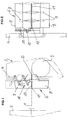
- the printed printing material web 1 passes through a dryer 2 downstream of the last printing unit, in which the fresh print is dried by supplying heat, and then through a cooling device 3, in which the in the dryer heated substrate 1 is cooled.
- the cooling device 3 generally consists of cooling rollers 5 arranged in a cooling roller stand 4. To compensate for the moisture given off by the printing material web in the dryer 2, the latter is subjected to rewetting.
- the latter is provided with spray nozzles 7 arranged above and below the printing material web 1 for applying rewetting liquid to the printing material web.
- the spray nozzles 7 are located in a housing which has a lower housing part 8 arranged below the transport plane of the printing material web 1 and a housing upper part 9 which can be placed thereon and arranged above the transport plane of the printing material web 1.
- the upper housing part 9 can be raised and lowered by means of a lifting device 10. In the raised position of the upper housing part 9, indicated by broken lines in FIG. 1, is a simple and easy insertion of the substrate 1 possible.
- the two housing parts are designed such that there is an inlet slot 11 assigned to the printing material web 1 on the inlet side and an outlet slot 12 assigned to the printing material web 1 on the outlet side.
- the two housing parts are sealed against one another by means of a suitable sealing strip 13 in the state in which they are placed one on top of the other.
- the lifting device 10 for lifting the upper housing part 9 consists of two parallel levers arranged in the manner of a parallelogram, which can be actuated by means of a lifting cylinder.
- the pivot levers and the lifting cylinder are accommodated on lateral brackets 14, with which the stationary lower housing part 8 is fastened to the stand 4 of the cooling device 3.
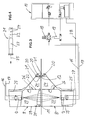
- the nozzles 7 provided in the lower housing part 8 and upper housing part 9, which can be arranged in the form of a row oriented transversely to the running direction of the printing material web 1 and can be distributed uniformly over the width, are supplied, as shown in FIG. 3, from a supply station 15.
- the supply station 15 can be integrated in the rewetting device.
- the example shown is based on a supply station provided, connected by lines to the respective consumers.
- the nozzles 7 are designed as two-substance nozzles which are exposed to liquid, which can generally be simple tap water, and air. Accordingly, two supply lines 16, 17 for liquid and air are assigned to each nozzle 7.
- the mixing ratio between liquid and air is adjustable.
- corresponding metering valves 18, 19 are arranged in the supply lines. This enables the mixing ratio of liquid and air to be adapted to the respective paper quality.
- the use of two-substance nozzles ensures that small liquid streams are formed which are not only distributed evenly over the width of the printing material web 1, but are also acted upon with high energy and accordingly have a high penetration force and thus reliably reach the printing material web 1.
- the printing material web 1 moving at high speed entrains air layers which are applied to its upper and lower sides and which must be penetrated by the liquid droplets in order to ensure reliable rewetting of the printing material web 1.
- the spray nozzles 7 generate an aerosol-like spray. At the same time, steam is generated.
- the printing material web 1 leaving the dryer 2 has a comparatively high temperature of often more than 100 ° C., so that a large amount of the liquid striking the printing material web 1 is evaporated.
- there are at the outlet slot 12 with respect to the transport plane the doctor blade web 1 opposing air doctor devices 20 are provided.
- the air doctor devices 20 work advantageously without contact and at the same time ensure that the outlet gap 12 can have a comparatively large clear width, so that the printing material web 1 does not come into contact with the gap edges even in the event of fluttering.
- Air knife devices of the type mentioned above can also be provided in the region of the inlet slot 11. As a rule, however, this is not necessary since the air layers entrained by the printing material web already ensure that no liquid can escape to the outside via the inlet slot 11. It would also be conceivable to provide such air doctor devices in the area of the passage slots of inner transverse walls of the housing. In the normal case, however, it is sufficient if, as in the example shown, only air knife devices are assigned to the outlet slot 12.
- the air doctor devices 20 each consist of a continuous over the entire slot width or width of the remoistening device 6 Pipe, which is arranged outside the outlet slot 12 obliquely above or obliquely below this and provided with nozzle bores, the axis of which is tilted forward in the direction of travel in relation to a solder on the substrate web plane, so that the rays 21 directed obliquely into the outlet gap 12 result.
- the lower housing part 8 and upper housing part 9, as shown in FIG. 3, are each divided into two chambers by an inner transverse wall 22, namely an inlet-side spray chamber 23 receiving the spray nozzles 7 and a nozzle-free condensation chamber 24 arranged downstream of the latter
- the partition wall 22 prevents the air doctor devices 20 from being acted upon directly by spray jets and liquid splashes etc. generated by the spray nozzles 7.
- the nozzleless condensation chambers 24 simultaneously result in a comparatively long evaporation section upstream of the outlet slot 12, within which excess liquid not absorbed by the printing material web 1 can evaporate, as a result of which heat is removed from the printing material web 1 in a desired manner, which can relieve the downstream cooling device 3.
- exhaust air chimneys 25 extending upwards or downwards are provided from the condensation chambers 24.
- Spraying takes place in the spray chambers 22.
- mist and liquid splashes are also deposited on the walls of the spray chamber 23, which can lead to droplets indicated at 26.
- Condensation of steam takes place in the condensation chambers 24.
- the vapor evaporating from the printing material web 1 in the condensation chambers 24 is deposited on the comparatively cold chamber walls, which may form accumulations, which are also indicated in FIG. 3 by droplets 26. This also applies to the exhaust air chimneys 25.
- the ceiling-side walls of the upper spray chamber 23 and the condensation chamber 24 are inclined so that the droplets formed there can run off without dripping.
- the Lower housing part 8 is a mirror image of the upper housing part 9, so that there are accordingly inclined floor surfaces.
- the lower spray chamber 23 is provided in the deepest area with a bottom-side outlet 27 which is connected to an outlet line 28 which leads back to the supply station 15. As a result, liquid running down the walls of the lower spray chamber 23 is returned to the supply station 15.
- the lower exhaust air chimney 25 is provided with a liquid outlet 27 which is connected to the drain line 28, so that the liquid running down the walls of the lower condensation chamber 24 and the lower exhaust air chimney 25 is also returned to the supply station 15.
- the precipitation on the walls of the upper housing part 9 extending in the running direction of the printing material web 1 can simply run past the respective sealing strip downwards and can thus be discharged via the respective liquid outlet 27, since the housing is wider than the printing material web 1.
- the precipitation on the walls of the upper housing part 9 running transversely to the running direction of the printing material web 1 is collected on the respective lower wall edge in order to prevent dripping onto the printing material web 1 and thus preventing it from becoming soiled and possibly softened.
- Arranged drip catcher 31 which receive and discharge the drops running down the respectively associated wall.
- the drip catchers 31 can be designed as gutters which enclose the lower edge of the respectively assigned wall.
- the drip catchers 31 are tubular and are attached to the respectively assigned wall in such a way that there is a small channel between the wall and the pipe circumference.
- the drip catchers 31, as can best be seen from FIG. 4, consist of an inner tube 32, onto which a stocking 33 made of textile material is fitted.
- the tube 32 is provided with one or more rows of holes 34, which are arranged so that the tube 32nd is closed down.
- an upper row of holes 34 is provided.
- the stocking 33 suitably consists of a close-knit textile material, such as velvet. This ensures good absorbency. Because of this absorbency, the liquid collected on the circumference of the drip catchers 31 thus formed is fed to the holes in the row of holes 34, via which the liquid enters the pipe 32 and can be removed from it.
- the pipes of the drip catchers 31 can be subjected to suction, as indicated by an arrow 35 in FIG. 4.
- the pipes 32 are closed at one end and connected to the suction port of a pump at the other end.
- a liquid separator can be provided, the outlet of which can open into the drain line 28, so that the liquid collected via the drip catchers 31 is also returned to the supply station 35.
Landscapes
- Engineering & Computer Science (AREA)
- Mechanical Engineering (AREA)
- Supply, Installation And Extraction Of Printed Sheets Or Plates (AREA)
- Drying Of Solid Materials (AREA)
Applications Claiming Priority (2)
| Application Number | Priority Date | Filing Date | Title |
|---|---|---|---|
| DE19615198A DE19615198C1 (de) | 1996-04-17 | 1996-04-17 | Vorrichtung zur Rückbefeuchtung einer Bedruckstoffbahn |
| DE19615198 | 1996-04-17 |
Publications (2)
| Publication Number | Publication Date |
|---|---|
| EP0802052A1 true EP0802052A1 (fr) | 1997-10-22 |
| EP0802052B1 EP0802052B1 (fr) | 1999-06-16 |
Family
ID=7791554
Family Applications (1)
| Application Number | Title | Priority Date | Filing Date |
|---|---|---|---|
| EP97104467A Expired - Lifetime EP0802052B1 (fr) | 1996-04-17 | 1997-03-15 | Dispositif pour le remouillage d'une bande imprimée |
Country Status (5)
| Country | Link |
|---|---|
| US (1) | US5813332A (fr) |
| EP (1) | EP0802052B1 (fr) |
| JP (1) | JPH106478A (fr) |
| DE (2) | DE19615198C1 (fr) |
| ES (1) | ES2135275T3 (fr) |
Cited By (1)
| Publication number | Priority date | Publication date | Assignee | Title |
|---|---|---|---|---|
| WO2000066365A1 (fr) * | 1999-05-03 | 2000-11-09 | Baldwin Grafotec Gmbh | Procede et dispositif pour le conditionnement d'une feuille continue de papier |
Families Citing this family (8)
| Publication number | Priority date | Publication date | Assignee | Title |
|---|---|---|---|---|
| US6152032A (en) * | 1998-11-05 | 2000-11-28 | Heidelberger Druckmaschinen Ag | Mist containment system for a spray dampener system |
| DE19901802B4 (de) * | 1999-01-19 | 2004-02-12 | Baldwin Germany Gmbh | Vorrichtung zur Rückbefeuchtung einer getrockneten Papierbahn |
| DE19901801C2 (de) * | 1999-01-19 | 2003-12-11 | Baldwin Germany Gmbh | Vorrichtung zum Konditionieren einer Papierbahn |
| DE19905824A1 (de) * | 1999-02-12 | 2000-09-07 | Weitmann & Konrad Fa | Vorrichtung zum Befeuchten von bahnförmigem Material |
| DE19954458A1 (de) * | 1999-11-12 | 2001-05-23 | Ltg Prozessluft Und Gebaeudete | Einhausung für eine drucktechnische Einrichtung |
| US20040045996A1 (en) * | 2002-09-06 | 2004-03-11 | Lamothe Richard P. | Web outfeed processing system for high performance printer |
| JP2008273032A (ja) * | 2007-04-27 | 2008-11-13 | Mitsubishi Heavy Ind Ltd | オフセット印刷機による印刷方法及びオフセット印刷機 |
| DE102015222753B4 (de) * | 2015-11-18 | 2019-02-28 | Koenig & Bauer Ag | Bearbeitungsvorrichtung für flaches Material und ein Verfahren zum Bearbeiten eines flachen Materials |
Citations (1)
| Publication number | Priority date | Publication date | Assignee | Title |
|---|---|---|---|---|
| DE4405332A1 (de) * | 1994-02-19 | 1995-08-31 | Bse Printtechnologie | Rückbefeuchtungssystem, insbesondere für Rollenoffsetmaschinen mit Heatsettrocknung |
Family Cites Families (6)
| Publication number | Priority date | Publication date | Assignee | Title |
|---|---|---|---|---|
| US2299026A (en) * | 1938-02-23 | 1942-10-13 | Carle J Merrill | Method of and apparatus for coating paper |
| DE3614742A1 (de) * | 1986-04-30 | 1987-11-05 | Heidelberger Druckmasch Ag | Einrichtung zur nachbehandlung einer beschichteten oder bedruckten gutbahn |
| US5184555A (en) * | 1989-04-19 | 1993-02-09 | Quad/Tech, Inc. | Apparatus for reducing chill roll condensation |
| US5040457A (en) * | 1989-10-10 | 1991-08-20 | Rockwell International Corporation | Printing press dampener |
| GB2251062B (en) * | 1990-12-20 | 1995-01-11 | Electricity Ass Services Ltd | An apparatus for enabling heat transfer between a first fluid and an elongate element |
| US5303652A (en) * | 1992-02-13 | 1994-04-19 | Baldwin Technology Corporation | Spray blanket cleaning system |
-
1996
- 1996-04-17 DE DE19615198A patent/DE19615198C1/de not_active Expired - Fee Related
-
1997
- 1997-02-21 JP JP9037311A patent/JPH106478A/ja active Pending
- 1997-03-15 EP EP97104467A patent/EP0802052B1/fr not_active Expired - Lifetime
- 1997-03-15 ES ES97104467T patent/ES2135275T3/es not_active Expired - Lifetime
- 1997-03-15 DE DE59700209T patent/DE59700209D1/de not_active Expired - Fee Related
- 1997-04-17 US US08/842,886 patent/US5813332A/en not_active Expired - Fee Related
Patent Citations (1)
| Publication number | Priority date | Publication date | Assignee | Title |
|---|---|---|---|---|
| DE4405332A1 (de) * | 1994-02-19 | 1995-08-31 | Bse Printtechnologie | Rückbefeuchtungssystem, insbesondere für Rollenoffsetmaschinen mit Heatsettrocknung |
Cited By (1)
| Publication number | Priority date | Publication date | Assignee | Title |
|---|---|---|---|---|
| WO2000066365A1 (fr) * | 1999-05-03 | 2000-11-09 | Baldwin Grafotec Gmbh | Procede et dispositif pour le conditionnement d'une feuille continue de papier |
Also Published As
| Publication number | Publication date |
|---|---|
| JPH106478A (ja) | 1998-01-13 |
| EP0802052B1 (fr) | 1999-06-16 |
| DE19615198C1 (de) | 1997-07-24 |
| DE59700209D1 (de) | 1999-07-22 |
| ES2135275T3 (es) | 1999-10-16 |
| US5813332A (en) | 1998-09-29 |
Similar Documents
| Publication | Publication Date | Title |
|---|---|---|
| DE3305749C2 (fr) | ||
| EP0699529B1 (fr) | Procédé et dispositif pour imprimer une bande | |
| DE3790947C2 (de) | Verfahren und Vorrichtung für eine Taschenventilation in der Trockenpartie einer Papiermaschine, insbesondere für schnellaufende Papiermaschinen | |
| DE60223666T2 (de) | Aggregat zur behandlung einer bahn aus papier oder pappe | |
| DE3431060A1 (de) | Trocknungseinrichtung und -verfahren zum abziehen von fluessigkeit von einer bewegten oberflaeche | |
| EP0802052B1 (fr) | Dispositif pour le remouillage d'une bande imprimée | |
| DE19901801C2 (de) | Vorrichtung zum Konditionieren einer Papierbahn | |
| DE19918130A1 (de) | Kühl- und Befeuchtungseinheit für Rotationsdruckmaschinen | |
| DE3207463C2 (de) | Verfahren und Vorrichtung zum Trocknen und anschließendem Kühlen von insbesondere nach dem Offsetdruckverfahren bedruckten Warenbahnen | |
| EP1022135B1 (fr) | Dispositif pour le remouillage d'une bande sechée de papier | |
| EP0708203A2 (fr) | Dispositif et méthode pour humidifier une bande de matériau en défilement | |
| DE60222429T2 (de) | Verfahren und gerät zum einblasen von trocknungsgas in eine papiermaschine | |
| CH623752A5 (fr) | ||
| EP1156893B1 (fr) | Procede et dispositif pour secher et maintenir sec en particulier un feuillard lamine a froid dans la zone de sortie d'installations de laminage a froid et de laminage de feuillards | |
| DE2716613C2 (de) | Vorrichtung zum Trocknen von bedruckten oder beschichteten Warenbahnen | |
| DE19827647A1 (de) | Verfahren zum Kantenleimen und Spannaggregat mit einer Vorrichtung zum Kantenleimen | |
| DE19710124B4 (de) | Verfahren und Vorrichtung zur Temperierung von Kühlwalzen | |
| DE60111936T2 (de) | Vorrichtung zur kühlung von bahnen mittels wasserspülung für einen wassertrockner | |
| DE69018135T2 (de) | Befeuchtungsvorrichtung für bandförmiges Material, insbesondere Papier. | |
| EP1456031A1 (fr) | Procedes et elements pyrotechniques pour humidifier sans contact un cylindre ou un rouleau de machine d'impression a plat | |
| DE202011107823U1 (de) | Anlage zur Verarbeitung einer Faserbahn | |
| DE8707384U1 (de) | Vorrichtung zur Bearbeitung von lösungsmittelhaltigem Material | |
| DE19920091A1 (de) | Verfahren und Vorrichtung zur Konditionierung einer Papierbahn | |
| DE102006027529A1 (de) | Vorrichtung zum berührungslosen Führen einer Materialbahn, insbesondere einer Papier- oder Kartonbahn, und Anordnung mit einer Beschichtungseinrichtung für eine Materialbahn und einer derartigen Vorrichtung | |
| EP1586700B1 (fr) | Machine à papier |
Legal Events
| Date | Code | Title | Description |
|---|---|---|---|
| PUAI | Public reference made under article 153(3) epc to a published international application that has entered the european phase |
Free format text: ORIGINAL CODE: 0009012 |
|
| AK | Designated contracting states |
Kind code of ref document: A1 Designated state(s): CH DE ES FR GB IT LI SE |
|
| 17P | Request for examination filed |
Effective date: 19980102 |
|
| GRAG | Despatch of communication of intention to grant |
Free format text: ORIGINAL CODE: EPIDOS AGRA |
|
| 17Q | First examination report despatched |
Effective date: 19980715 |
|
| GRAG | Despatch of communication of intention to grant |
Free format text: ORIGINAL CODE: EPIDOS AGRA |
|
| GRAH | Despatch of communication of intention to grant a patent |
Free format text: ORIGINAL CODE: EPIDOS IGRA |
|
| RAP1 | Party data changed (applicant data changed or rights of an application transferred) |
Owner name: BALDWIN GRAFOTEC GMBH |
|
| GRAH | Despatch of communication of intention to grant a patent |
Free format text: ORIGINAL CODE: EPIDOS IGRA |
|
| GRAA | (expected) grant |
Free format text: ORIGINAL CODE: 0009210 |
|
| AK | Designated contracting states |
Kind code of ref document: B1 Designated state(s): CH DE ES FR GB IT LI SE |
|
| REG | Reference to a national code |
Ref country code: CH Ref legal event code: EP |
|
| REF | Corresponds to: |
Ref document number: 59700209 Country of ref document: DE Date of ref document: 19990722 |
|
| GBT | Gb: translation of ep patent filed (gb section 77(6)(a)/1977) |
Effective date: 19990727 |
|
| ET | Fr: translation filed | ||
| REG | Reference to a national code |
Ref country code: ES Ref legal event code: FG2A Ref document number: 2135275 Country of ref document: ES Kind code of ref document: T3 |
|
| PLBE | No opposition filed within time limit |
Free format text: ORIGINAL CODE: 0009261 |
|
| STAA | Information on the status of an ep patent application or granted ep patent |
Free format text: STATUS: NO OPPOSITION FILED WITHIN TIME LIMIT |
|
| 26N | No opposition filed | ||
| PG25 | Lapsed in a contracting state [announced via postgrant information from national office to epo] |
Ref country code: LI Free format text: LAPSE BECAUSE OF NON-PAYMENT OF DUE FEES Effective date: 20010331 Ref country code: CH Free format text: LAPSE BECAUSE OF NON-PAYMENT OF DUE FEES Effective date: 20010331 |
|
| REG | Reference to a national code |
Ref country code: CH Ref legal event code: PL |
|
| REG | Reference to a national code |
Ref country code: GB Ref legal event code: IF02 |
|
| PGFP | Annual fee paid to national office [announced via postgrant information from national office to epo] |
Ref country code: GB Payment date: 20030211 Year of fee payment: 7 |
|
| PGFP | Annual fee paid to national office [announced via postgrant information from national office to epo] |
Ref country code: FR Payment date: 20030212 Year of fee payment: 7 |
|
| PGFP | Annual fee paid to national office [announced via postgrant information from national office to epo] |
Ref country code: SE Payment date: 20030213 Year of fee payment: 7 |
|
| PGFP | Annual fee paid to national office [announced via postgrant information from national office to epo] |
Ref country code: ES Payment date: 20030227 Year of fee payment: 7 |
|
| PG25 | Lapsed in a contracting state [announced via postgrant information from national office to epo] |
Ref country code: GB Free format text: LAPSE BECAUSE OF NON-PAYMENT OF DUE FEES Effective date: 20040315 |
|
| PG25 | Lapsed in a contracting state [announced via postgrant information from national office to epo] |
Ref country code: SE Free format text: LAPSE BECAUSE OF NON-PAYMENT OF DUE FEES Effective date: 20040316 Ref country code: ES Free format text: LAPSE BECAUSE OF NON-PAYMENT OF DUE FEES Effective date: 20040316 |
|
| EUG | Se: european patent has lapsed | ||
| GBPC | Gb: european patent ceased through non-payment of renewal fee |
Effective date: 20040315 |
|
| PG25 | Lapsed in a contracting state [announced via postgrant information from national office to epo] |
Ref country code: FR Free format text: LAPSE BECAUSE OF NON-PAYMENT OF DUE FEES Effective date: 20041130 |
|
| REG | Reference to a national code |
Ref country code: FR Ref legal event code: ST |
|
| PG25 | Lapsed in a contracting state [announced via postgrant information from national office to epo] |
Ref country code: IT Free format text: LAPSE BECAUSE OF NON-PAYMENT OF DUE FEES;WARNING: LAPSES OF ITALIAN PATENTS WITH EFFECTIVE DATE BEFORE 2007 MAY HAVE OCCURRED AT ANY TIME BEFORE 2007. THE CORRECT EFFECTIVE DATE MAY BE DIFFERENT FROM THE ONE RECORDED. Effective date: 20050315 |
|
| REG | Reference to a national code |
Ref country code: ES Ref legal event code: FD2A Effective date: 20040316 |
|
| PGFP | Annual fee paid to national office [announced via postgrant information from national office to epo] |
Ref country code: DE Payment date: 20070209 Year of fee payment: 11 |
|
| PG25 | Lapsed in a contracting state [announced via postgrant information from national office to epo] |
Ref country code: DE Free format text: LAPSE BECAUSE OF NON-PAYMENT OF DUE FEES Effective date: 20081001 |