EP0802073B1 - Luftreifen - Google Patents
Luftreifen Download PDFInfo
- Publication number
- EP0802073B1 EP0802073B1 EP97302444A EP97302444A EP0802073B1 EP 0802073 B1 EP0802073 B1 EP 0802073B1 EP 97302444 A EP97302444 A EP 97302444A EP 97302444 A EP97302444 A EP 97302444A EP 0802073 B1 EP0802073 B1 EP 0802073B1
- Authority
- EP
- European Patent Office
- Prior art keywords
- sipe
- block
- tire
- groove
- circumferential
- Prior art date
- Legal status (The legal status is an assumption and is not a legal conclusion. Google has not performed a legal analysis and makes no representation as to the accuracy of the status listed.)
- Expired - Lifetime
Links
- 230000001154 acute effect Effects 0.000 claims description 9
- 230000000052 comparative effect Effects 0.000 description 17
- 230000000694 effects Effects 0.000 description 3
- 230000000593 degrading effect Effects 0.000 description 2
- 230000009466 transformation Effects 0.000 description 2
- 230000006835 compression Effects 0.000 description 1
- 238000007906 compression Methods 0.000 description 1
- 238000010276 construction Methods 0.000 description 1
- 239000004744 fabric Substances 0.000 description 1
Images

Classifications
-
- B—PERFORMING OPERATIONS; TRANSPORTING
- B60—VEHICLES IN GENERAL
- B60C—VEHICLE TYRES; TYRE INFLATION; TYRE CHANGING; CONNECTING VALVES TO INFLATABLE ELASTIC BODIES IN GENERAL; DEVICES OR ARRANGEMENTS RELATED TO TYRES
- B60C11/00—Tyre tread bands; Tread patterns; Anti-skid inserts
- B60C11/03—Tread patterns
- B60C11/12—Tread patterns characterised by the use of narrow slits or incisions, e.g. sipes
- B60C11/1272—Width of the sipe
- B60C11/1281—Width of the sipe different within the same sipe, i.e. enlarged width portion at sipe bottom or along its length
-
- Y—GENERAL TAGGING OF NEW TECHNOLOGICAL DEVELOPMENTS; GENERAL TAGGING OF CROSS-SECTIONAL TECHNOLOGIES SPANNING OVER SEVERAL SECTIONS OF THE IPC; TECHNICAL SUBJECTS COVERED BY FORMER USPC CROSS-REFERENCE ART COLLECTIONS [XRACs] AND DIGESTS
- Y10—TECHNICAL SUBJECTS COVERED BY FORMER USPC
- Y10S—TECHNICAL SUBJECTS COVERED BY FORMER USPC CROSS-REFERENCE ART COLLECTIONS [XRACs] AND DIGESTS
- Y10S152/00—Resilient tires and wheels
- Y10S152/03—Slits in threads
-
- Y—GENERAL TAGGING OF NEW TECHNOLOGICAL DEVELOPMENTS; GENERAL TAGGING OF CROSS-SECTIONAL TECHNOLOGIES SPANNING OVER SEVERAL SECTIONS OF THE IPC; TECHNICAL SUBJECTS COVERED BY FORMER USPC CROSS-REFERENCE ART COLLECTIONS [XRACs] AND DIGESTS
- Y10—TECHNICAL SUBJECTS COVERED BY FORMER USPC
- Y10S—TECHNICAL SUBJECTS COVERED BY FORMER USPC CROSS-REFERENCE ART COLLECTIONS [XRACs] AND DIGESTS
- Y10S152/00—Resilient tires and wheels
- Y10S152/902—Non-directional tread pattern having no circumferential rib and having blocks defined by circumferential grooves and transverse grooves
Definitions
- This invention relates to a pneumatic tire, and is concerned with restraint of uneven wear of a pneumatic tire, in particular restraint of uneven wear of a pneumatic tire of a block pattern provided with blocks having acute angle corners.
- lateral grooves in block-type tread patterns adopted on normal passenger tires are mostly arranged not to be parallel with the axial direction of the tire and the blocks are shaped as parallelograms.
- sipes or fine grooves substantially parallel with the axis of the tire to obtain steering stability on a wet road.
- sipes made rigidity distribution of the blocks unbalanced, so that the blocks were distorted in the ground contact area and uneven wear was produced.
- the rigidity of the blocks as a whole was lowered and steering stability was degraded. Therefore, means such as making the lateral grooves or sipes shallow was used.
- the above mentioned shallowing of the grooves or the sipes caused poor drainage and bad appearance at the terminal stage of use of the tire.
- a tire according to the preamble of claim 1 is known from JP-A-01-132406.
- An object of the present invention is to overcome the above mentioned disadvantages of the prior art, and provide a pneumatic tire which restrains uneven wear without degrading drainage and appearance at the terminal stage of use of the tire.
- the present invention provides a pneumatic tire having a tread provided with at least one circumferential groove extending substantially parallel with the tire circumferential direction, and inclined grooves arranged at intervals in the circumferential direction of the tire, the inclined grooves being inclined at an angle with respect to the circumferential groove and the axial direction, and blocks formed by the circumferential groove and the inclined grooves and arranged at intervals in the circumferential direction of the tire, the blocks having acute angle corners and obtuse angle corners at both sides which contact the ground earlier and later in the block during tire rotating and which are formed by the circumferential groove or by a tread end and the respective inclined grooves,
- the tread end means the end of the ground contact area of the tread in the width direction.
- an auxiliary sipe having shallower depth than the sipe is formed to connect with the sipe, and the auxiliary sipe extends substantially in parallel with the inclined groove and reaches an opposite block edge. That is, the auxiliary sipe opens to another circumferential groove or a tread end which is located on the opposite side of the circumferential groove to which the sipe opens.
- the length of sipe is 30 - 70% of a distance from the opening to the opposite block edge through the terminal end of the sipe.
- the sipe is arranged apart from the nearest inclined groove by 2mm or more and not more than 30% of the circumferential length of the block when measured in a direction perpendicular to the nearest inclined groove.
- the depth of the auxiliary sipe is 20 - 70% of that of the sipe.
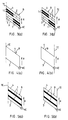
- the drawing (a) shows a block B wherein the tread edge TE is located at the left-hand side as shown
- the drawing (b) shows a block B wherein the tread edge TE is located at the right-hand side as shown.
- the reference letter R indicates the direction of rotation of the tire
- the reference numerals 4 and 3 respectively indicate the stepping-in end and the stepping-out end of the block when the block contacts the ground during the tire rotation.
- the reference letters KC and KE indicate acute angle corners of the block at the stepping-out end where uneven wear occurs; KC indicates wear adjacent a circumferential groove in each of the drawings (a), and KE indicates wear adjacent a tread end in each of the drawings (b).
- sipes 1 extend respectively from a tread end side and from a circumferential groove side of the block and terminate in the block, as shown.
- sipes 1 are provided in a similar manner to the sipes in Fig. 1, and in addition auxiliary sipes 2 having shallower depth than the sipes 1 are formed to connect with the sipes 1 and extend to the respective opposite block edge.
- Figs. 3(a) and 3(b) which illustrate a second embodiment of a tire according to the invention
- sipes 1 and auxiliary sipes 2 are provided in a similar manner as in Fig. 2, except than in Fig. 3 pairs of sipes 1 and pairs of auxiliary sipes 2 are provided, as shown.
- Figs. 4(a) and 4(b) which illustrate a tire of a first comparative example, no sipes are provided in the blocks B.
- sipes 1 are provided in each block B, as shown, but in this case the respective sipes extend continuously from the tread end to the circumferential groove across the whole length of the block.
- a sipe opening to the circumferential groove and a sipe opening to the tread end in the block; however, there may be formed only sipes which open to the circumferential groove or there may be formed only sipes which open to the tread end.
- stepping-out end of the block means a block end which contacts the ground later between block ends in the block during tire rotating, when viewing one block among many blocks formed by circumferential grooves and inclined grooves and arranged in the circumferential direction at intervals.
- This uneven wear particularly occurs at the stepping-out end KC, KE near the block corner where, as shown in Fig. 4, the circumferential groove or the tread end crosses the inclined groove at an acute angle.
- the length of the sipe is preferably set at 30 - 70% of the distance from the opening to the opposite block edge through the terminal end of the sipe. This is because, if the length of the sipe is less than 30%, the effect to separate the portion KC, KE from the block is small and wear may not be sufficiently reduced, and if the length of the sipe is more than 70%, the rigidity of the whole block becomes small and steering stability is degraded.
- the sipe is preferably arranged apart from the nearest inclined groove by 2mm or more and not more than 30% of the circumferential length of the block when measured in a direction at a right angle to the nearest inclined groove. This is because, if said distance is less than 2mm, the rigidity of the block end portion is lowered, and if said distance is more than 30%, the rigidity is too high, and in both cases the effect provided by the sipe may not be sufficient.
- the depth of the auxiliary sipe is preferably set at 20 - 70% of that of the sipe. This is because, if the depth of the auxiliary sipe is less than 20% of that of the sipe, the auxiliary sipe may disappear at a relatively early stage of use, and if the depth of the auxiliary sipe is more than 70% of that of the sipe, the rigidity as a whole becomes small and the steering stability is degraded.
- a further sipe and a further auxiliary sipe can be added near the acute angle comer of the step-in end, which enters the ground contact area earlier.
- the tires of the present invention and of comparative examples are each provided with a large number of blocks having a shape as shown in Figs. 1 to 5 near the tread end portion in the circumferential direction of the tires.
- the inclined grooves which partially define the blocks extend at an angle of 30° with respect to the circumferential direction.
- the depth of each of the inclined grooves and the circumferential grooves is 8mm.
- the circumferential length of the blocks is about 31mm, and the length of the blocks in the width direction is 36mm. Because the blocks near the tread end portion suffer larger volume of wear (uneven wear) than those at the center portion of the tire and largely contribute to steering stability, tests were carried out with respect to the blocks at the tread end portion.
- Fig. 4 shows a block of comparative example 1 provided with no sipes.
- Fig. 5 shows a block of comparative example 2 provided with sipes 1 which have a width of 0.7mm and depth of 6mm and extend parallel with a inclined groove continuously from the tread end to a circumferential groove. Specification of the sipes of examples 1 - 20 and comparative examples are described in Table 1 below. In order to examine the effect of the present invention, twenty-two test tires were prepared based on the tires of the examples and the comparative examples, and comparative tests were carried out in relation to uneven wear and steering property. The tires of the examples and the comparative example 2 have the same construction as the tire of the comparative example 1 except for having sipes as described in Table 1.
- each tire was mounted on a rim having a size of 51 ⁇ 2J with inflation pressure of 1.9kgf/cm 2 , and the test was carried out by using a flat-belt wear test machine having a cloth file on it.
- the tire was run according to the following conditions - room temperature: 30°C; load: 450kgf; slip angle: 0.4°; braking force: 45kgf; speed: 50km/h; and mileage: 200km.
- Step distance of wear which is defined as normal distance between a worn surface at the block end KC, KE and the surface of the remaining portion of the block, was evaluated by using comparative example 1 as a control having an index value of 100. The results obtained are shown in Table 1 below. The smaller the value, the better the result.
- each tire was mounted on a rim having a size of 51 ⁇ 2J with inflation pressure of 1.9kgf/cm 2 , and cornering power (CP) was measured by using a flat-belt test machine with load of 50kgf. Cornering power here means cornering force per slip angle of 1°. In this test, average value of cornering power when slip angle varies from 0° to 7° is indicated by using comparative example 1 as a control having an index value of 100. The results obtained are also shown in Table 1. The larger the value, the larger is the cornering power and the better is the steering property. Sipe length Sipe depth Sipe position Auxiliary sipe depth Uneven (a) KC wear (b) KE CP Comp. Example 1 (Fig.
- Example 18 is not however an example of the invention.
- the tires according to the invention improve uneven wear in comparison with the tire of comparative example 1.
- cornering power is improved in comparison with the tire of comparative example 2, and it is more preferable that the value of cornering power (CP) is not less than about 85% of the value of the comparative example 1.
- the present invention thus provides a pneumatic tire which restrains uneven wear at the shoulder portion without degrading steering property.
Landscapes
- Engineering & Computer Science (AREA)
- Mechanical Engineering (AREA)
- Tires In General (AREA)
Claims (4)
- Luftreifen, mit einer Lauffläche, die mit mindestens einer Umfangsrille versehen ist, die sich im wesentlichen parallel zu der Umfangsrichtung des Reifens erstreckt, und geneigten Rillen, die in der Umfangsrichtung des Reifens in Abständen angeordnet sind, wobei die geneigten Rillen unter einem Winkel bezüglich der Umfangsrille und der axialen Richtung geneigt sind, und Blöcken (B), die durch die Umfangsrille und die geneigten Rillen gebildet werden und in der Umfangsrichtung des Reifens in Abständen angeordnet sind, wobei die Blöcke (B) auf beiden Seiten spitzwinklige Ecken (KC, KE) und stumpfwinklige Ecken haben, die während der Reifendrehung bei dem Block (B) den Boden früher und später berühren und die durch die Umfangsrille oder durch einen Laufflächenrand (TE) und die jeweiligen geneigten Rillen gebildet werden,wobei ein Einschnitt (1) nahe bei der spitzwinkligen Ecke (KC, KE) gebildet ist, der während der Reifendrehung bei dem Block (B) den Boden später berührt, wobei der Einschnitt (1) eine Öffnung bei der Umfangsrille oder bei dem Laufflächenrand (TE) hat, und der Einschnitt (1) sich von der Öffnung zu der Innenseite des Blocks (B) hin im wesentlichen parallel zu der geneigten Rille erstreckt und in dem Block (B) endet,dadurch gekennzeichnet, daß ein Hilfseinschnitt (2), der eine geringere Tiefe als der Einschnitt (1) hat, nahe bei der stumpfwinkligen Ecke, die während der Reifendrehung bei dem Block (B) den Boden später berührt, gebildet ist, und mit dem Einschnitt (1) verbunden ist, wobei sich der Hilfseinschnitt (2) im wesentlichen parallel zu der geneigten Rille erstreckt und bis zu dem jeweiligen entgegengesetzten Blockrand reicht.
- Luftreifen wie in Anspruch 1 beansprucht, dadurch gekennzeichnet, daß die Länge des Einschnitts (1) 30-70% der Entfernung von der Öffnung an dem entgegengesetzten Blockrand bis zu dem terminalen Ende des Einschnitts beträgt.
- Luftreifen wie in Anspruch 1 oder 2 beansprucht, dadurch gekennzeichnet, daß der Einschnitt (1) um 2 mm oder mehr, und um nicht mehr als 30% der Umfangslänge des Blocks (B) von der nächsten geneigten Rille entfernt ist, wenn in einer zu der nächsten geneigten Rille senkrechten Richtung gemessen wird.
- Luftreifen wie in irgendeinem der Ansprüche 1 bis 3 beansprucht, dadurch gekennzeichnet, daß die Tiefe des Hilfseinschnitts (2) 20-70% der Tiefe des Einschnitts (1) beträgt.
Applications Claiming Priority (6)
| Application Number | Priority Date | Filing Date | Title |
|---|---|---|---|
| JP9892196 | 1996-04-19 | ||
| JP98921/96 | 1996-04-19 | ||
| JP9892196 | 1996-04-19 | ||
| JP2361597 | 1997-02-06 | ||
| JP02361597A JP3681850B2 (ja) | 1996-04-19 | 1997-02-06 | 空気入りタイヤ |
| JP23615/97 | 1997-02-06 |
Publications (2)
| Publication Number | Publication Date |
|---|---|
| EP0802073A1 EP0802073A1 (de) | 1997-10-22 |
| EP0802073B1 true EP0802073B1 (de) | 2001-06-20 |
Family
ID=26361013
Family Applications (1)
| Application Number | Title | Priority Date | Filing Date |
|---|---|---|---|
| EP97302444A Expired - Lifetime EP0802073B1 (de) | 1996-04-19 | 1997-04-09 | Luftreifen |
Country Status (5)
| Country | Link |
|---|---|
| US (1) | US5871598A (de) |
| EP (1) | EP0802073B1 (de) |
| JP (1) | JP3681850B2 (de) |
| DE (1) | DE69705256T2 (de) |
| ES (1) | ES2159086T3 (de) |
Families Citing this family (23)
| Publication number | Priority date | Publication date | Assignee | Title |
|---|---|---|---|---|
| JP4272301B2 (ja) * | 1998-06-18 | 2009-06-03 | 住友ゴム工業株式会社 | トレッドパタ−ン形成方法 |
| US6503354B1 (en) | 1999-11-12 | 2003-01-07 | Jonathan Martindale | System and method for reducing blistering in automobile racing tires |
| USD449024S1 (en) | 2000-06-14 | 2001-10-09 | The Goodyear Tire & Rubber Company | Tire tread |
| US6446689B1 (en) | 2000-06-14 | 2002-09-10 | The Goodyear Tire & Rubber Company | Pneumatic tire having 80 to 105 pitches |
| US6439285B1 (en) | 2000-06-14 | 2002-08-27 | The Goodyear Tire & Rubber Company | Pneumatic tire having 98 pitches |
| US6435237B1 (en) | 2000-06-14 | 2002-08-20 | The Goodyear Tire & Rubber Company | Pneumatic tire having generally rounded footprint shape |
| USD451440S1 (en) | 2000-12-04 | 2001-12-04 | The Goodyear Tire & Rubber Company | Tire tread |
| USD451441S1 (en) | 2000-12-04 | 2001-12-04 | The Goodyear Tire & Rubber Company | Tire tread |
| USD453730S1 (en) | 2001-05-03 | 2002-02-19 | The Goodyear Tire & Rubber Company | Tire tread |
| USD458897S1 (en) | 2001-05-22 | 2002-06-18 | The Goodyear Tire & Rubber Company | Tire tread |
| USD458899S1 (en) | 2001-06-27 | 2002-06-18 | The Goodyear Tire & Rubber Company | Tire tread |
| USD464020S1 (en) | 2001-09-24 | 2002-10-08 | The Goodyear Tire & Rubber Company | Tire tread |
| DE10257487A1 (de) * | 2002-12-10 | 2004-07-01 | Continental Aktiengesellschaft | Fahrzeugluftreifen zum Einsatz unter winterlichen Fahrbedingungen |
| DE102004014006A1 (de) * | 2004-03-23 | 2005-10-13 | Continental Ag | Fahrzeugluftreifen |
| JP4751164B2 (ja) * | 2005-10-06 | 2011-08-17 | 株式会社ブリヂストン | 空気入りタイヤ |
| JP4925798B2 (ja) * | 2006-11-28 | 2012-05-09 | 株式会社ブリヂストン | 空気入りタイヤ |
| US7950426B2 (en) | 2007-06-08 | 2011-05-31 | Bridgestone Americas Tire Operations, Llc | Tread blocks having reduced edge stiffness |
| KR100889206B1 (ko) | 2008-04-01 | 2009-03-17 | 금호타이어 주식회사 | 이상마모를 방지한 공기입 타이어 |
| JP5835112B2 (ja) * | 2012-06-05 | 2015-12-24 | 横浜ゴム株式会社 | 空気入りタイヤ |
| JP6138536B2 (ja) * | 2013-03-19 | 2017-05-31 | 株式会社ブリヂストン | 空気入りタイヤ |
| CN104029568A (zh) * | 2014-06-11 | 2014-09-10 | 厦门正新橡胶工业有限公司 | 摩托车充气轮胎胎面结构 |
| JP6878971B2 (ja) * | 2017-03-15 | 2021-06-02 | 住友ゴム工業株式会社 | タイヤ |
| US10981418B2 (en) | 2017-11-27 | 2021-04-20 | Sumitomo Rubber Industries, Ltd. | Tire |
Family Cites Families (9)
| Publication number | Priority date | Publication date | Assignee | Title |
|---|---|---|---|---|
| JPH069922B2 (ja) * | 1983-05-12 | 1994-02-09 | 住友ゴム工業株式会社 | 良路高速走行重荷重用ラジアルタイヤ |
| JPS61291205A (ja) * | 1985-06-20 | 1986-12-22 | Bridgestone Corp | サイプエツジの鮮鋭なタイヤトレツド |
| JP2772638B2 (ja) * | 1987-11-16 | 1998-07-02 | 横浜ゴム株式会社 | 空気入りラジアルタイヤ |
| JP2821886B2 (ja) * | 1988-08-27 | 1998-11-05 | 横浜ゴム株式会社 | ライトトラック用空気入りタイヤ |
| JPH0314704A (ja) * | 1989-06-09 | 1991-01-23 | Toyo Tire & Rubber Co Ltd | 空気入りタイヤ |
| FR2667544B1 (fr) * | 1990-10-03 | 1993-07-02 | Michelin & Cie | Equipement pneumatique pour un vehicule roulant sur sols enneiges, verglaces. |
| JPH0740711A (ja) * | 1993-06-29 | 1995-02-10 | Yokohama Rubber Co Ltd:The | 乗用車用空気入りラジアルタイヤ |
| JPH0781328A (ja) * | 1993-09-13 | 1995-03-28 | Yokohama Rubber Co Ltd:The | 空気入りラジアルタイヤ |
| FI944892L (fi) * | 1993-11-18 | 1995-08-18 | Bridgestone Corp | Pneumaattinen rengas |
-
1997
- 1997-02-06 JP JP02361597A patent/JP3681850B2/ja not_active Expired - Fee Related
- 1997-04-09 EP EP97302444A patent/EP0802073B1/de not_active Expired - Lifetime
- 1997-04-09 ES ES97302444T patent/ES2159086T3/es not_active Expired - Lifetime
- 1997-04-09 DE DE69705256T patent/DE69705256T2/de not_active Expired - Lifetime
- 1997-04-18 US US08/837,454 patent/US5871598A/en not_active Expired - Lifetime
Also Published As
| Publication number | Publication date |
|---|---|
| DE69705256T2 (de) | 2002-05-16 |
| EP0802073A1 (de) | 1997-10-22 |
| ES2159086T3 (es) | 2001-09-16 |
| JP3681850B2 (ja) | 2005-08-10 |
| JPH10906A (ja) | 1998-01-06 |
| US5871598A (en) | 1999-02-16 |
| DE69705256D1 (de) | 2001-07-26 |
Similar Documents
| Publication | Publication Date | Title |
|---|---|---|
| EP0802073B1 (de) | Luftreifen | |
| EP0202122B1 (de) | Luftreifen | |
| EP2199111B1 (de) | Luftreifen mit Lamellen | |
| US4884606A (en) | Pneumatic tires having improved wet performances | |
| EP2163405B1 (de) | Luftreifen | |
| JP2650040B2 (ja) | 乗用車用空気入りタイヤ | |
| EP0715973B1 (de) | Luftreifen für vereiste/verschneite Böden | |
| US6102093A (en) | Pneumatic tire including long blocks and wide blocks | |
| EP0904960B1 (de) | Spikeloser luftreifen | |
| EP2692543B1 (de) | Luftreifen | |
| EP1645441B1 (de) | Luftreifen | |
| EP0798137B1 (de) | Radialer luftreifen | |
| EP0713789A1 (de) | PKW-Luftreifen | |
| EP1127715A2 (de) | Blockstruktur in Luftreifen | |
| EP1010551B1 (de) | Luftreifen | |
| JPH0680002A (ja) | 重荷重用空気入りラジアルタイヤ | |
| US6935392B2 (en) | Pneumatic tire including slant main grooves and sipes | |
| AU2004278228A1 (en) | Pneumatic tire | |
| JPH10244813A (ja) | 空気入りタイヤ | |
| EP3828011B1 (de) | Reifenlauffläche | |
| EP1661733B1 (de) | Luftreifen | |
| JP2001322406A (ja) | 空気入りタイヤ | |
| JP3547186B2 (ja) | 空気入りラジアルタイヤ | |
| RU2766465C1 (ru) | Универсальная шина | |
| JP3631559B2 (ja) | 空気入りタイヤ |
Legal Events
| Date | Code | Title | Description |
|---|---|---|---|
| PUAI | Public reference made under article 153(3) epc to a published international application that has entered the european phase |
Free format text: ORIGINAL CODE: 0009012 |
|
| AK | Designated contracting states |
Kind code of ref document: A1 Designated state(s): DE ES FR GB IT |
|
| 17P | Request for examination filed |
Effective date: 19971204 |
|
| 17Q | First examination report despatched |
Effective date: 19990412 |
|
| GRAG | Despatch of communication of intention to grant |
Free format text: ORIGINAL CODE: EPIDOS AGRA |
|
| GRAG | Despatch of communication of intention to grant |
Free format text: ORIGINAL CODE: EPIDOS AGRA |
|
| GRAH | Despatch of communication of intention to grant a patent |
Free format text: ORIGINAL CODE: EPIDOS IGRA |
|
| GRAH | Despatch of communication of intention to grant a patent |
Free format text: ORIGINAL CODE: EPIDOS IGRA |
|
| GRAA | (expected) grant |
Free format text: ORIGINAL CODE: 0009210 |
|
| AK | Designated contracting states |
Kind code of ref document: B1 Designated state(s): DE ES FR GB IT |
|
| REF | Corresponds to: |
Ref document number: 69705256 Country of ref document: DE Date of ref document: 20010726 |
|
| ITF | It: translation for a ep patent filed | ||
| ET | Fr: translation filed | ||
| REG | Reference to a national code |
Ref country code: ES Ref legal event code: FG2A Ref document number: 2159086 Country of ref document: ES Kind code of ref document: T3 |
|
| REG | Reference to a national code |
Ref country code: GB Ref legal event code: IF02 |
|
| PLBE | No opposition filed within time limit |
Free format text: ORIGINAL CODE: 0009261 |
|
| STAA | Information on the status of an ep patent application or granted ep patent |
Free format text: STATUS: NO OPPOSITION FILED WITHIN TIME LIMIT |
|
| 26N | No opposition filed | ||
| PGFP | Annual fee paid to national office [announced via postgrant information from national office to epo] |
Ref country code: GB Payment date: 20120404 Year of fee payment: 16 Ref country code: FR Payment date: 20120504 Year of fee payment: 16 |
|
| PGFP | Annual fee paid to national office [announced via postgrant information from national office to epo] |
Ref country code: IT Payment date: 20120418 Year of fee payment: 16 |
|
| PGFP | Annual fee paid to national office [announced via postgrant information from national office to epo] |
Ref country code: ES Payment date: 20120424 Year of fee payment: 16 |
|
| GBPC | Gb: european patent ceased through non-payment of renewal fee |
Effective date: 20130409 |
|
| PG25 | Lapsed in a contracting state [announced via postgrant information from national office to epo] |
Ref country code: GB Free format text: LAPSE BECAUSE OF NON-PAYMENT OF DUE FEES Effective date: 20130409 |
|
| REG | Reference to a national code |
Ref country code: FR Ref legal event code: ST Effective date: 20131231 |
|
| PG25 | Lapsed in a contracting state [announced via postgrant information from national office to epo] |
Ref country code: FR Free format text: LAPSE BECAUSE OF NON-PAYMENT OF DUE FEES Effective date: 20130430 Ref country code: IT Free format text: LAPSE BECAUSE OF NON-PAYMENT OF DUE FEES Effective date: 20130409 |
|
| REG | Reference to a national code |
Ref country code: ES Ref legal event code: FD2A Effective date: 20140610 |
|
| PG25 | Lapsed in a contracting state [announced via postgrant information from national office to epo] |
Ref country code: ES Free format text: LAPSE BECAUSE OF NON-PAYMENT OF DUE FEES Effective date: 20130410 |
|
| PGFP | Annual fee paid to national office [announced via postgrant information from national office to epo] |
Ref country code: DE Payment date: 20140418 Year of fee payment: 18 |
|
| REG | Reference to a national code |
Ref country code: DE Ref legal event code: R081 Ref document number: 69705256 Country of ref document: DE Owner name: BRIDGESTONE CORPORATION, JP Free format text: FORMER OWNER: BRIDGESTONE CORP., TOKIO/TOKYO, JP Effective date: 20140828 |
|
| REG | Reference to a national code |
Ref country code: DE Ref legal event code: R119 Ref document number: 69705256 Country of ref document: DE |
|
| PG25 | Lapsed in a contracting state [announced via postgrant information from national office to epo] |
Ref country code: DE Free format text: LAPSE BECAUSE OF NON-PAYMENT OF DUE FEES Effective date: 20151103 |