EP0802086A2 - Dispositif de commande multifonctions - Google Patents
Dispositif de commande multifonctions Download PDFInfo
- Publication number
- EP0802086A2 EP0802086A2 EP97200788A EP97200788A EP0802086A2 EP 0802086 A2 EP0802086 A2 EP 0802086A2 EP 97200788 A EP97200788 A EP 97200788A EP 97200788 A EP97200788 A EP 97200788A EP 0802086 A2 EP0802086 A2 EP 0802086A2
- Authority
- EP
- European Patent Office
- Prior art keywords
- selection
- function
- control device
- trackball
- field
- Prior art date
- Legal status (The legal status is an assumption and is not a legal conclusion. Google has not performed a legal analysis and makes no representation as to the accuracy of the status listed.)
- Ceased
Links
Images
Classifications
-
- G—PHYSICS
- G06—COMPUTING OR CALCULATING; COUNTING
- G06F—ELECTRIC DIGITAL DATA PROCESSING
- G06F3/00—Input arrangements for transferring data to be processed into a form capable of being handled by the computer; Output arrangements for transferring data from processing unit to output unit, e.g. interface arrangements
- G06F3/01—Input arrangements or combined input and output arrangements for interaction between user and computer
- G06F3/03—Arrangements for converting the position or the displacement of a member into a coded form
- G06F3/033—Pointing devices displaced or positioned by the user, e.g. mice, trackballs, pens or joysticks; Accessories therefor
- G06F3/038—Control and interface arrangements therefor, e.g. drivers or device-embedded control circuitry
Definitions
- the invention relates to a multifunction control device for vehicles, which allows a selection of function groups (menus) or individual functions.
- Such a multifunction control device is known from EP-0 366 132.
- This multifunction control device has a bidirectional rotary switch, which is used for menu selection and individual function selection.
- the rotary switch has rest positions to which individual menus or individual functions are assigned.
- An enter function can be triggered by axial movement of the rotary switch.
- This multifunctional operating device has the disadvantage that a selection of selection fields which are arranged two-dimensionally and are displayed, for example, on a screen, is always always possible in the horizontal or only in the vertical direction. It is difficult in this way to work through to a certain point in such a two-dimensional menu, which, for example, lies in an oblique direction at an angle of 45 ° to the starting position.
- the multifunction control device has a trackball that serves the selection of function groups and / or functions and by means of which by rotating the trackball and depending on the direction of rotation and extent of rotation of the trackball individual function groups and / or selection fields assigned to functions It can be selected that selection fields provided one after the other in this direction of movement can be selected when the trackball is rotated in any direction, and that a selection field selected by means of the trackball is particularly optically marked.
- Such a trackball allows the direction to be specified directly by rotating the trackball in the desired direction via the multifunction control device. This means that not only entries in the vertical or horizontal direction are possible, but also entries in any direction between these two directions. Selection fields are symbolized on a screen and can be selected by moving the trackball. The selected selection field is optically marked. Moving the trackball does not allow the marker to move continuously, as is the case with computers, for example. Rather, when the trackball is moved in a certain direction, the selection fields arranged in this direction are selected one after the other. So there is a discontinuous movement in the manner of jumping the cursor.
- the trackball in a selection field in which a plurality of selection fields are arranged on a screen in a two-dimensional plane, the trackball can be used to mark the desired selection field to which the desired function group and / or function is assigned in an extremely simple manner. The user can move the trackball in any direction to the desired selection field until it is selected and visually identified.
- an enter function for activating a function group and / or a function whose assigned selection field is selected can be triggered by pressing the trackball.
- the enter function can be triggered in a simple manner without having to press an additional key.
- the trackball not only offers a universal selection option in a two-dimensional level, but also the possibility of triggering an enter function, i.e. activating a function group and / or a function.
- the selection of the selection fields which can be carried out as a function of the trackball movement is software-controlled.
- the selection fields provided in this direction are selected one after the other. So there is a disquantine jumping of the marked selection field.
- the detection of the direction of movement and the detection that, depending on the direction of rotation of the trackball and depending on the extent of the rotation, the selection of a selection field in a specific direction is desired can advantageously be controlled by software.
- Such software is easily adaptable to changing environmental conditions. It is also conceivable that the software can be adjusted to the user, for example how sensitive the operating device is to the rotation of the trackball, i.e. For example, what range of rotation is required to jump from one selected selection field to the next selection field and select it.
- the multifunction control device has a sensor field which serves for a selection of function groups and / or functions and by means of which an operator is assigned to individual function groups and / or functions on a sensor field on the sensor field Screen symbolized selection fields can be selected in such a way that when the operator's finger is guided on the sensor field in any direction one after the other in this direction of movement provided selection fields are selected, and that a selection field selected by means of the sensor field is particularly optically marked.
- a sensor field by moving a finger, an operator can be informed in a certain direction of the operating device in which direction the cursor should move, i.e. that is, the direction in which selection fields should be selected one after the other. Depending on the duration of guiding the finger or how far the finger is guided in this direction, selection fields provided in this direction of movement are selected one after the other.
- a function group or an individual function are assigned to each selection field.
- the sensor field is arranged separately from the screen on which the selection fields are symbolized.
- the desired direction can be predetermined by moving the finger in any direction. There is no binding to specific horizontal or vertical directions. The operator can move in any direction in a field which is displayed two-dimensionally on the screen and has these selection fields.
- an enter function for activating a function group and / or a function whose assigned selection field is selected can be triggered by means of intensified pressure on the sensor field.
- the selected sensor field can be activated by increasing pressure on the sensor field. This triggers the function or function group assigned to this sensor field. There is the advantage that no further operating device is required for this enter function. Rather, the sensor field can also be used to trigger the enter function.
- the selection of the selection fields which can be carried out as a function of the movement of the operator's finger on the sensor field is software-controlled.
- the disquantine jumping of the selected selection fields can be controlled in an ideal manner.
- the multifunction control device is installed in the vehicle in such a way that the operator's hand can be supported on part of the vehicle. Such an installation ensures that the selection of the desired selection field can also take place while the vehicle is traveling and is not disturbed in the event of any vibrations.
- the multifunction control device can advantageously be installed in a handle or shift lever of the vehicle, as is provided according to a further embodiment of the invention. This gives the operator direct access to the multifunction control device.
- Such a multifunction control device can advantageously be used to control an audio, an information and / or a navigation system of a vehicle.
- Such a multi-function control device can advantageously be used for several systems at the same time, since a corresponding menu selection, which can be carried out in a simple manner by means of the multi-function control device, can be used to select between many different function groups. A simple selection of the individual functions is then possible within the function groups.
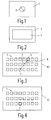
- FIG. 1 shows a multifunction control device 1 of a first embodiment, which has a trackball 2.
- the trackball 2 can be rotated in any direction. It allows the selection of functions or function groups. This selection is made by selecting the respectively assigned selection fields on an assigned screen, which, however, is arranged separately from the multifunction control device 1 shown in FIG. 1.
- FIG. 2 shows a second embodiment of the multifunction control device according to the invention.
- a multi-function control device there 3 indicated, which has a sensor field 4.
- An operator can select selection fields indicated in succession in this direction on a separately arranged screen by moving a finger on the sensor field 4 in the desired direction. Similar to the trackball of the operating device 1 according to FIG. 1, it also applies to this operating device with the sensor field 4 that a movement can take place in any direction.
- the multifunction control device 3 shown in FIG. 2 with the sensor field 4 additionally allows an enter function to be triggered. This activates the selected selection field, i.e. the assigned function or function group is triggered.
- FIG. 3 shows a schematic representation of a screen 10, which is advantageously arranged separately from one of the operating devices 1 or 3 according to FIGS. 1 or 2.
- selection fields 11 are shown thinly, which can be selected.
- a function group or function is assigned to each of the selection fields 11.
- a selection field 5 is first selected.
- This selection field 5 is shown in thick in the illustration according to FIG. 3.
- This selection field can be activated, for example, after switching on the multifunction control device or the assigned screen, but it can also be the function or function group that was previously selected.
- selection field 7 instead of the selection field 5
- an operator can operate either the trackball 2 of the operating device 1 according to FIG. 1 or the sensor field 4 of the operating device 3 according to FIG. 2 so that the selection field 6 of the illustration is displayed first 3 and below, the selection field 7 can be selected.
- These fields then appear optically highlighted one after the other, for example by displaying the edges of the selection field in bold.
- the trackball 2 is rotated in the corresponding direction and with the corresponding range of rotation.
- the successive selection of the selection fields 5, 6 can be carried out, for example, in a software-controlled manner in the direction of the arrow 8, as shown in FIG. 3.
- the second embodiment of the multifunction control device according to FIG. 2 can be used to select the selection fields on the screen 10 according to FIG. 3.
- a finger of the operator is guided in the desired direction via the sensor field 4 of the multifunction control device 3 according to FIG. 2.
- the selection fields 5, 6, 7 are activated in succession.
- FIG. 3 shows that the multifunction control devices 1 and 3 according to FIGS. 1 and 2 allow a selection of selection fields in any direction. It is not only possible to make a selection in certain predetermined directions.
- FIG. 4 finally shows the screen 10 according to FIG. 3, in which the desired selection field 7 is now selected and is shown visually. If the function or function group assigned to this selection field 7 is to be triggered, this can be done by pressing the trackball 2 of the operating device 1 according to FIG. 1 or by intensified pressure on the sensor field 4 of the operating device 3 according to FIG. 2.
Landscapes
- Engineering & Computer Science (AREA)
- General Engineering & Computer Science (AREA)
- Theoretical Computer Science (AREA)
- Human Computer Interaction (AREA)
- Physics & Mathematics (AREA)
- General Physics & Mathematics (AREA)
- Position Input By Displaying (AREA)
- User Interface Of Digital Computer (AREA)
- Switches With Compound Operations (AREA)
- Digital Computer Display Output (AREA)
Applications Claiming Priority (2)
| Application Number | Priority Date | Filing Date | Title |
|---|---|---|---|
| DE19611551 | 1996-03-23 | ||
| DE1996111551 DE19611551A1 (de) | 1996-03-23 | 1996-03-23 | Multifunktions-Bedieneinrichtung |
Publications (2)
| Publication Number | Publication Date |
|---|---|
| EP0802086A2 true EP0802086A2 (fr) | 1997-10-22 |
| EP0802086A3 EP0802086A3 (fr) | 1998-07-08 |
Family
ID=7789223
Family Applications (1)
| Application Number | Title | Priority Date | Filing Date |
|---|---|---|---|
| EP97200788A Ceased EP0802086A3 (fr) | 1996-03-23 | 1997-03-17 | Dispositif de commande multifonctions |
Country Status (3)
| Country | Link |
|---|---|
| EP (1) | EP0802086A3 (fr) |
| JP (1) | JPH1064374A (fr) |
| DE (1) | DE19611551A1 (fr) |
Families Citing this family (5)
| Publication number | Priority date | Publication date | Assignee | Title |
|---|---|---|---|---|
| WO1999048725A1 (fr) * | 1998-03-25 | 1999-09-30 | Lear Automotive Dearborn, Inc. | Plaque frontale d'ordinateur de poche servant a communiquer avec un ordinateur de voiture |
| DE19829568A1 (de) * | 1998-07-02 | 2000-01-05 | Mannesmann Vdo Ag | Bedieneinheit einer fest in einem Fahrzeug installierten Vorrichtung |
| DE19910240A1 (de) * | 1999-03-08 | 2000-09-21 | Mannesmann Vdo Ag | Bedienvorrichtung |
| AT4609U1 (de) | 2000-06-16 | 2001-09-25 | Magna Eybl Gmbh | Kraftfahrzeug und innenausstattungsteil für ein kraftfahrzeug |
| JP4836050B2 (ja) * | 2005-09-15 | 2011-12-14 | 株式会社デンソー | 車載電子機器用入力システム |
Family Cites Families (5)
| Publication number | Priority date | Publication date | Assignee | Title |
|---|---|---|---|---|
| JPH03137686A (ja) * | 1989-10-24 | 1991-06-12 | Mazda Motor Corp | タッチパネル装置 |
| IT1264834B1 (it) * | 1993-06-16 | 1996-10-17 | Francesco Silvano Di | Unita' di impugnatura della leva del cambio diretto di un autoveicolo, raggruppante vari comandi |
| DE4334800A1 (de) * | 1993-10-13 | 1994-05-19 | Allhoff Cramer Adalbert | Lenkschalteinrichtung in Kraftfahrzeugen |
| GB2283080A (en) * | 1993-10-22 | 1995-04-26 | Central Research Lab Ltd | Computer input mouse. |
| DE59507169D1 (de) * | 1994-09-13 | 1999-12-09 | Siemens Ag | Multifunktions-Bedieneinrichtung |
-
1996
- 1996-03-23 DE DE1996111551 patent/DE19611551A1/de not_active Withdrawn
-
1997
- 1997-03-17 EP EP97200788A patent/EP0802086A3/fr not_active Ceased
- 1997-03-24 JP JP9069759A patent/JPH1064374A/ja not_active Abandoned
Also Published As
| Publication number | Publication date |
|---|---|
| JPH1064374A (ja) | 1998-03-06 |
| DE19611551A1 (de) | 1997-09-25 |
| EP0802086A3 (fr) | 1998-07-08 |
Similar Documents
| Publication | Publication Date | Title |
|---|---|---|
| EP1262740B1 (fr) | Système d'ordinateur véhiculaire et procédé de commande d'un curseur pour système d'ordinateur véhiculaire | |
| DE19730297B4 (de) | Bedienvorrichtung mit zweidimensionaler Dialogbewegung | |
| EP0796756B1 (fr) | Dispositif de commande de fonctions d'un véhicule contrôlés à partir d'un menu | |
| DE60115085T2 (de) | Vorrichtung zur verarbeitung der bewegung eines zeigers auf einem bildschirm | |
| EP0961198A2 (fr) | Dispositif électronique aven un interrupteur rotatif et une écran d' affichage | |
| DE19610700A1 (de) | Bedienvorrichtung für menügesteuerte Funktionen eines Fahrzeugs | |
| WO2010025781A1 (fr) | Procédé et dispositif pour l'affichage d'informations dans un véhicule | |
| EP0412308A2 (fr) | Calculateur électronique ayant une représentation des fonctions des touches programmables | |
| EP0525531A2 (fr) | Pupitre de commande pour machines d'usinage et de mesure | |
| EP3513261A2 (fr) | Dispositif de commande permettant de faire fonctionner une machine-outil, en particulier une fraiseuse ou un tour, et machine-outil correspondante | |
| EP0802086A2 (fr) | Dispositif de commande multifonctions | |
| DE60006149T2 (de) | Verfahren zur steuerung einer berührungsempfindlichen oberfläche | |
| DE102009037401A1 (de) | Fahrzeug mit einer Bedieneinrichtung | |
| EP0718994A2 (fr) | Dispositif pour le traitement de siganux audibles | |
| EP0284007A2 (fr) | Dispositif pour introduire des données dans une machine à imprimer | |
| DE202024100451U1 (de) | Bedieneinheit für ein Fahrzeug | |
| EP1177566B3 (fr) | Dispositif permettant d'entrer des valeurs et dote d'un ecran | |
| EP1212741B1 (fr) | Dispositif de navigation | |
| DE102014016020A1 (de) | Steuerungsanordnung mit Lenkradbedienung | |
| DE10119648B4 (de) | Anordnung zur Bedienung von fernsehtechnischen Geräten | |
| DE10359561A1 (de) | Bedienelement für ein Haushaltsgerät | |
| DE69019718T2 (de) | Steuerungsvorrichtung von Funktionen an Bord eines Kraftfahrzeugs. | |
| EP1433606B1 (fr) | Procédé et dispositif pour commander une machine à imprimer | |
| DE19941967B4 (de) | Verfahren und Vorrichtung zur Bewegung eines Aktivierungselementes auf einer Anzeigeeinheit | |
| DE102019125662A1 (de) | Bedienhilfe, Fernsteuerung und Verfahren zur Fernsteuerung |
Legal Events
| Date | Code | Title | Description |
|---|---|---|---|
| PUAI | Public reference made under article 153(3) epc to a published international application that has entered the european phase |
Free format text: ORIGINAL CODE: 0009012 |
|
| AK | Designated contracting states |
Kind code of ref document: A2 Designated state(s): DE FR GB |
|
| PUAL | Search report despatched |
Free format text: ORIGINAL CODE: 0009013 |
|
| AK | Designated contracting states |
Kind code of ref document: A3 Designated state(s): DE FR GB |
|
| RAP3 | Party data changed (applicant data changed or rights of an application transferred) |
Owner name: KONINKLIJKE PHILIPS ELECTRONICS N.V. Owner name: PHILIPS PATENTVERWALTUNG GMBH |
|
| 17P | Request for examination filed |
Effective date: 19990108 |
|
| RAP3 | Party data changed (applicant data changed or rights of an application transferred) |
Owner name: KONINKLIJKE PHILIPS ELECTRONICS N.V. Owner name: PHILIPS CORPORATE INTELLECTUAL PROPERTY GMBH |
|
| 17Q | First examination report despatched |
Effective date: 20000630 |
|
| RAP1 | Party data changed (applicant data changed or rights of an application transferred) |
Owner name: KONINKLIJKE PHILIPS ELECTRONICS N.V. Owner name: PHILIPS CORPORATE INTELLECTUAL PROPERTY GMBH |
|
| RAP1 | Party data changed (applicant data changed or rights of an application transferred) |
Owner name: KONINKLIJKE PHILIPS ELECTRONICS N.V. Owner name: PHILIPS INTELLECTUAL PROPERTY & STANDARDS GMBH |
|
| STAA | Information on the status of an ep patent application or granted ep patent |
Free format text: STATUS: THE APPLICATION HAS BEEN REFUSED |
|
| 18R | Application refused |
Effective date: 20050206 |