EP0802102A1 - Verrou d'extrémité d'aiguille - Google Patents
Verrou d'extrémité d'aiguille Download PDFInfo
- Publication number
- EP0802102A1 EP0802102A1 EP97106375A EP97106375A EP0802102A1 EP 0802102 A1 EP0802102 A1 EP 0802102A1 EP 97106375 A EP97106375 A EP 97106375A EP 97106375 A EP97106375 A EP 97106375A EP 0802102 A1 EP0802102 A1 EP 0802102A1
- Authority
- EP
- European Patent Office
- Prior art keywords
- slide rod
- pressure pieces
- end closure
- rail
- tongue
- Prior art date
- Legal status (The legal status is an assumption and is not a legal conclusion. Google has not performed a legal analysis and makes no representation as to the accuracy of the status listed.)
- Granted
Links
- 230000007797 corrosion Effects 0.000 claims abstract description 6
- 238000005260 corrosion Methods 0.000 claims abstract description 6
- 210000002105 tongue Anatomy 0.000 claims description 62
- 229910000742 Microalloyed steel Inorganic materials 0.000 claims description 5
- ZOKXTWBITQBERF-UHFFFAOYSA-N Molybdenum Chemical compound [Mo] ZOKXTWBITQBERF-UHFFFAOYSA-N 0.000 claims description 3
- 229910052750 molybdenum Inorganic materials 0.000 claims description 3
- 239000011733 molybdenum Substances 0.000 claims description 3
- 229910000831 Steel Inorganic materials 0.000 claims description 2
- 239000010959 steel Substances 0.000 claims description 2
- 238000012423 maintenance Methods 0.000 description 11
- 238000000034 method Methods 0.000 description 6
- 238000005461 lubrication Methods 0.000 description 5
- 238000006073 displacement reaction Methods 0.000 description 2
- 238000004519 manufacturing process Methods 0.000 description 2
- 229910000746 Structural steel Inorganic materials 0.000 description 1
- 239000011248 coating agent Substances 0.000 description 1
- 238000000576 coating method Methods 0.000 description 1
- 238000005553 drilling Methods 0.000 description 1
- 238000005516 engineering process Methods 0.000 description 1
- 239000000463 material Substances 0.000 description 1
- 229910052751 metal Inorganic materials 0.000 description 1
- 239000002184 metal Substances 0.000 description 1
- 238000003825 pressing Methods 0.000 description 1
- 230000001360 synchronised effect Effects 0.000 description 1
Images

Classifications
-
- B—PERFORMING OPERATIONS; TRANSPORTING
- B61—RAILWAYS
- B61L—GUIDING RAILWAY TRAFFIC; ENSURING THE SAFETY OF RAILWAY TRAFFIC
- B61L5/00—Local operating mechanisms for points or track-mounted scotch-blocks; Visible or audible signals; Local operating mechanisms for visible or audible signals
- B61L5/10—Locking mechanisms for points; Means for indicating the setting of points
-
- E—FIXED CONSTRUCTIONS
- E01—CONSTRUCTION OF ROADS, RAILWAYS, OR BRIDGES
- E01B—PERMANENT WAY; PERMANENT-WAY TOOLS; MACHINES FOR MAKING RAILWAYS OF ALL KINDS
- E01B7/00—Switches; Crossings
- E01B7/02—Tongues; Associated constructions
-
- E—FIXED CONSTRUCTIONS
- E01—CONSTRUCTION OF ROADS, RAILWAYS, OR BRIDGES
- E01B—PERMANENT WAY; PERMANENT-WAY TOOLS; MACHINES FOR MAKING RAILWAYS OF ALL KINDS
- E01B2202/00—Characteristics of moving parts of rail systems, e.g. switches, special frogs, tongues
- E01B2202/04—Nature of the support or bearing
- E01B2202/044—Rolling
- E01B2202/046—Rolling with rolls on fixed part
-
- E—FIXED CONSTRUCTIONS
- E01—CONSTRUCTION OF ROADS, RAILWAYS, OR BRIDGES
- E01B—PERMANENT WAY; PERMANENT-WAY TOOLS; MACHINES FOR MAKING RAILWAYS OF ALL KINDS
- E01B2202/00—Characteristics of moving parts of rail systems, e.g. switches, special frogs, tongues
- E01B2202/08—Locking devices or mechanisms for inhibiting movement
Definitions
- the invention relates to a switch end closure for moving and fixing railroad switch tongues.
- a point setting system includes one or more clamp closures and a point end closure, which are connected to each other via linkage or each have a separate drive.
- the one or more clamp closures and the turnout end closure ensure synchronous adjustment of different distances, the turnout or turnout closures having the task of moving the turnout tongues and locking them in their end position.
- the turnout end closure serves to carry the movable tongue rail in a controlled manner in the turnout end area and to bring it on one side into contact with the stock rail.
- the tongue rail is brought to the stock rail at a predefined distance, the so-called drive-through groove.
- a predefined drive-through groove must exist so that the wheels of a rail vehicle do not rub against the tongue rail and damage it, or even run onto the tongue rail and derail.
- the standard system GMV of Deutsche Bahn AG is well known in technology.
- the system consists of an insulated slide rod on which eight pressure pieces are screwed on.
- the slide rod with the pressure pieces screwed on becomes horizontal in the longitudinal direction the slide rod moves.
- the thrust pieces on the pushrod engage the tongue block to which the tongue rail is attached and move the tongue rail attached to the tongue block towards or away from the stock rail. This will ensure correct tracking.
- a guide piece is attached to the stock rail, which is provided with an opening through which the slide rod passes.
- the slide rod When the slide rod is actuated, it slides through the guide piece fixed to the stock rail, which requires regular lubrication of the slide rod.
- the slide rod passes through a U-shaped recess in the tongue block. Regular lubrication of the slide rod is therefore also necessary in the area of the block guide.
- Both the slide rod and the pressure pieces screwed onto it have a toothing, via which the pressure pieces are positioned relative to the position of the tongue block.
- eight thrust pieces are screwed onto a slide rod.
- Two pressure pieces fastened on opposite sides of the slide rod each form a stop or a driving element for the tongue block.
- the pressure pieces are provided with a toothing on the side facing the slide rod in the installed position and the slide rod has a corresponding toothing in the contact area with the pressure pieces.
- the invention has for its object to propose a switch end closure that is easy to manufacture and as low maintenance as possible.
- the switch end closure for moving and fixing railroad switch tongues comprises a slide rod which is mounted on corrosion-resistant, maintenance-free rollers, the rollers being arranged in guide pieces which can be fastened to the stock rail.
- the friction between the slide rod and the guide pieces is significantly reduced and there is no need to lubricate the slide rods in the area in question.
- the regular maintenance work can be significantly reduced.
- the displacement of the slide rod is always smooth, so that the actuating forces required to move it are lower. Therefore can finally the performance of the actuator can also be designed accordingly lower.
- a switch end closure for moving and fixing railroad switch tongues with a slide rod on which pressure pieces can be fastened characterized in that the pressure pieces are arranged on one side and in the installed position on top of the slide rod.
- the pressure pieces are only arranged on one side on the slide rod, the number of pressure pieces to be assembled is halved compared to conventional systems. This is not a disadvantage compared to the conventional systems, because tests and observations have shown that when using conventional systems, usually only one of the thrust pieces arranged on both sides of the slide rod hits the tongue block. In contrast to the conventional systems, the pressure pieces are installed on top of the slide rod. This offers the advantage that when the pressure pieces on the slide rod are adjusted or readjusted, they are easily accessible to the switch mechanic. This simplifies the maintenance work involved.
- the slide rod is guided between U-shaped legs of a tongue block and the sliding contact surfaces of the slide rod are molybdenum-coated in the area of the tongue block.
- the slide rod is provided in the area of the attachment of the pressure pieces with a toothing or corrugation which is designed to correspond to a toothing or corrugation on the pressure pieces.
- a continuous adjustment of the pressure pieces in the longitudinal direction of the slide rod is excluded, the defined displacement of the pressure pieces in the area of the toothing or corrugation facilitates the adjustment and readjustment as part of maintenance work.
- the pressure pieces are preferably adjustable in the longitudinal direction of the slide rod.
- Two of the four pressure pieces can advantageously be fastened on an entire slide rod. Two of the four pressure pieces are in contact with the tongue block after an adjustment process and press the tongue rail against the stock rail or keep it at a predetermined distance from the stock rail.
- steel bolts with an external thread are pressed into the slide rod in the area of the attachment of the pressure pieces.
- the fastening elements between the slide rod and the pressure pieces are captively connected to the slide rod and only suitable, self-locking nuts have to be screwed on to fix the pressure pieces.
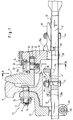
- Fig. 1 a part of the turnout closure 10 for moving and fixing railroad switch tongues is shown in a partial sectional view.
- the slide rod half 12 which is firmly connected to a further slide rod half on the side shown on the right in the drawing plane of FIG. 1, serves to move a tongue rail 14 in a targeted manner. While the tongue rail 14 shown in FIG. 1 is pressed firmly against the stock rail 16, the second tongue rail 14, not shown in FIG. 1, is held in the region of the other half of the push rod at a defined distance from the stock rail, as a result of which a drive-through groove with a predetermined distance between Tongue splint and stock splint is formed.
- the stock rail 16 represents a conventional railroad rail, such as that used by the Deutsche Bahn AG under the designation UIC 60.
- a tongue block 18 is fastened to the tongue rail 14, the fastening preferably being carried out with the aid of a fastening screw 20 which is guided in an eccentric bushing 22 and thus enables adjustment of the tongue rail in the longitudinal direction of the slide rod.
- Reference numeral 24 denotes a locking pin which is inserted through a through hole in the tongue block 18, is secured against falling out and prevents the fastening screw 20 from loosening unintentionally or falling out in the event of a break in the thread.
- the fastening screw 20 is provided with split pin openings 26 through which a split pin (not shown in FIG.
- the locking plate 26a is preferably formed with a 12-hole to form a hexagon of the fastening screw 20.
- the locking plate 26a is secured in height by a split pin, not shown in FIG. 1, in the split pin opening 26.
- the tongue block 18 is fork-shaped in the region of the slide rod 12, only one leg 28 of the tongue block 18 being visible in the sectional view shown in FIG. 1.
- the slide rod is guided with sufficient play in all directions between the two legs 28 of the tongue block.
- the tongue block 18 is preferably forged from microalloyed steel. As a result, wear is reduced and the service life can be increased compared to the use of a component forged from unalloyed structural steel.
- the guide piece 32 is fixedly attached to the stock rail 16, a turnout screw 34 being used for this purpose, on the U-shaped web of which two screw bolts are fixed at a distance corresponding to the position of the standard holes of Deutsche Bahn AG.
- the bolts of the turnout screw 34 are inserted through the existing holes in the stock rail 16, the guide piece 32 is placed on the threaded bolts and the guide piece is fastened with turnout nuts 36.
- Turnout nuts have a defined width across flats, for which the suitable tool is available in the limited tool set of turnout mechanics from Deutsche Bahn AG.
- the guide piece is also preferably forged from microalloyed steel.
- the slide rod 12 When setting the switch, the slide rod 12 is axial, i. H. in the direction of their longitudinal extension by a suitable drive.
- This drive can either be connected separately to the slide rod 12 or the slide rod is connected via linkage to one or more clamp closures and the clamp closure or closures as well as the switch end closure are actuated by means of a common drive.
- the slide rod 12 is moved horizontally in the longitudinal direction and pressure pieces 38 fastened to the slide rod bring about the desired track adjustment.
- the pressure piece 38a shown in Fig. 1 is in contact with the tongue block 18 and thus presses the tongue rail 14 attached to the tongue block against the stock rail 16.
- the tongue block is moved on the one hand relative to the stock rail and thus the tongue rail is moved in the direction of the stock rail and the further held the tongue rail in firm contact with the stock rail after completion of the adjustment process.
- the other slide rod half not shown in FIG. 1 also has pressure pieces 38a and 38b, the pressure piece 38b corresponding to the position shown in FIG. 1 on the other slide rod half being in contact with the tongue block 18 and removing it from the stock rail 16 by a predetermined distance holds.
- This predetermined distance which is referred to as the drive-through groove, represents a fixed, predetermined size and serves to prevent the wheels of a rail vehicle from being removed undesired contact with the tongue rail and possibly derail.
- the pressure piece 38b comes into contact with the tongue block and moves it in the plane of the drawing in FIG. 1 to the right until the desired drive-through groove between the stock rail and the tongue rail is produced has been.
- the tongue block then lies against the pressure piece 38b and is fixed in this position until another adjustment process is carried out.
- the pressure pieces 38a, 38b are made of metal and are preferably forged from microalloyed steel. On the side facing the slide rod 12, the pressure pieces have a toothing or corrugation which is designed to correspond to a toothing or corrugation 40 which is made on the upper side of the slide rod 12 in the installed position. This creates a positive contact between the pressure pieces and the slide rod and it is possible to perform a defined, gradual adjustment of the pressure pieces.
- the pressure pieces are each provided with an elongated hole 42 through which a fastening bolt 44 can pass, which is preferably pressed into the slide rod 12 in the region of the toothing 40. Pressing in the fastening bolt 44 has the advantage that it is captively connected to the slide rod 12 and therefore the maintenance and assembly work can be simplified.
- a washer 46 is placed on a flat, appropriately shaped support in the area of the elongated hole 42 and a self-locking nut is screwed onto the external thread of the fastening bolt 44.
- a so-called Gally nut could be used, which is self-locking and can be used several times.
- the pressure pieces have a stop area on the side facing the tongue block 18, in which the pressure piece has a fork-shaped shape, the legs 50 extending on both sides of the slide rod 12 and at the same time the stop area in the installed position rises far enough above the slide rod 12, to form a sufficiently large contact area with the tongue block 18.
- the fastening nut 48 To the thrust pieces in the axial direction, d. H. to move or adjust in the longitudinal direction of the slide rod, the fastening nut 48 must be loosened until the pressure piece in question can be lifted up beyond the engagement area of the toothing 40. The pressure piece can then be displaced axially, the fastening bolt 44, which is firmly pressed into the slide rod, moving in the longitudinal direction of the elongated hole 42. Finally, the self-locking nut 48 is tightened again.
- Fig. 2 shows a guide piece 32 with attached switch screw 34, the guide roller 30 and the slide rod 12, which rests on the guide roller 30.
- the guide piece 32 is fastened to the stock rail with the aid of a turnout screw 34, on the U-shaped web of which two screw bolts are fixed at a distance corresponding to the position of the standard holes of Deutsche Bahn AG.
- the bolts of the turnout screw 34 are inserted through the existing holes in the stock rails, the guide piece 32 is placed on the threaded bolts and this is fastened with turnout nuts 36.
- a locking plate 52 To solve the To prevent switch nuts 36, their rotational movement is prevented by a locking plate 52.
- the locking plate 52 is secured by a locking bolt 54, the bore of which is located in the middle between the two standard bores for the screw bolts. With the help of a locking pin 56, the movement of the locking plate 52 in the axial direction of the turnout screw 34 is prevented.
- the guide piece 32 has two legs, between which the slide rod 12 extends and the guide roller 30 is attached.
- the guide roller 30 runs on an axle pin 58, which is inserted through through holes in the legs of the guide piece 32 and in a suitable manner, for. B. is secured with a safety pin 60 against loosening.
- the guide roller 30 is formed from a corrosion-resistant material and has a central bore in the longitudinal direction through which the axle bolt 58 passes. As a result, the guide roller is rotatable relative to the axle bolt.
- the guide roller 30 forms a support for the slide rod 12 which, due to the line contact between the slide rod and the rotatable guide roller, is guided with little effort and therefore without the need for lubrication.
- a distance d is formed between the slide rod 12 and the legs of the guide piece 32, which is approximately 10 mm. This prevents jamming of the slide rod in the guide piece and the maintenance work required in the event of jamming of loosening the guide piece, realigning and fastening is eliminated.
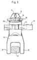
- FIG. 3 shows a sectional view along the line AA in FIG. 1.
- the fastening of the tongue block 18 on the tongue rail is visible in more detail than in FIG. 1.
- a split pin 66 is visible, which is by the Splint openings are inserted in the fastening screw 20 and prevents the fastening screw 20 from being twisted unintentionally.
- a wedge 64 (see also FIG. 1) is hammered in between the tongue block and tongue rail and secured with a locking plate 62. Both the wedge 64 and the locking plate 62 are standard parts of the switch mechanics.
- the tongue block 18 has a forked shape with two legs 28, between which the slide rod 12 is guided.
- the slide rod is preferably coated with molybdenum, which is why manual lubrication of the slide rod is not required in this area. The maintenance effort can thus be further reduced.
- the wear of the turnout end closure according to the invention can be reduced and the service life of the components can be increased. Due to the use of standard elements from Deutsche Bru, adjustment and adjustment work can be carried out easily and without any problems, since the tools required for this are carried by the turnout mechanics.
- the turnout end closure according to the invention can be used in the box-shaped track sleepers which have long been known in the art and can also be used to counteract horizontal systems are replaced. No new drilling patterns are required on the tongue and stock rail.
Landscapes
- Engineering & Computer Science (AREA)
- Mechanical Engineering (AREA)
- Architecture (AREA)
- Civil Engineering (AREA)
- Structural Engineering (AREA)
- Railway Tracks (AREA)
- Train Traffic Observation, Control, And Security (AREA)
Applications Claiming Priority (2)
| Application Number | Priority Date | Filing Date | Title |
|---|---|---|---|
| DE19615196A DE19615196A1 (de) | 1996-04-17 | 1996-04-17 | Weichenendverschluß |
| DE19615196 | 1996-04-17 |
Publications (2)
| Publication Number | Publication Date |
|---|---|
| EP0802102A1 true EP0802102A1 (fr) | 1997-10-22 |
| EP0802102B1 EP0802102B1 (fr) | 2003-07-02 |
Family
ID=7791553
Family Applications (1)
| Application Number | Title | Priority Date | Filing Date |
|---|---|---|---|
| EP97106375A Expired - Lifetime EP0802102B1 (fr) | 1996-04-17 | 1997-04-17 | Verrou d'extrémité d'aiguille |
Country Status (2)
| Country | Link |
|---|---|
| EP (1) | EP0802102B1 (fr) |
| DE (2) | DE19615196A1 (fr) |
Cited By (9)
| Publication number | Priority date | Publication date | Assignee | Title |
|---|---|---|---|---|
| WO2000002759A1 (fr) * | 1998-07-09 | 2000-01-20 | Siemens Schweiz Ag | Dispositif de fermeture |
| EP1078839A1 (fr) * | 1999-08-24 | 2001-02-28 | CARL DAN. PEDDINGHAUS GMBH & CO. KG | Dispositif d' haubanage entre une lame d'aiguillage et l'ensemble d'articulation associé |
| WO2001014200A1 (fr) * | 1999-08-24 | 2001-03-01 | Carl Dan. Peddinghaus Gmbh & Co. Kg | Systeme de verrouillage d'extremite d'aiguillage |
| EP1110841A1 (fr) * | 1999-12-23 | 2001-06-27 | CARL DAN. PEDDINGHAUS GMBH & CO. KG | Tige coulissante |
| EP1190927A1 (fr) * | 2000-09-21 | 2002-03-27 | Siemens Schweiz AG | Dispositif d'ajustage des lames d'aiguillage de surveillance dans un système de manoeuvre d'aiguille |
| AT410809B (de) * | 1999-05-07 | 2003-08-25 | Enzesfeld Caro Metallwerke Ag | Weiche für gleise des schienengebundenen verkehrs |
| CN101870300A (zh) * | 2009-04-22 | 2010-10-27 | 施维哈克股份公司 | 铁路道岔中的转换装置 |
| EP2684758A1 (fr) * | 2012-07-13 | 2014-01-15 | Siemens Schweiz AG | Verrou à pince destiné à retenir fermement une lame d'aiguillage ouverte |
| WO2016165109A1 (fr) * | 2015-04-16 | 2016-10-20 | Alstom Transport Technologies | Procédé et appareil pour un dispositif d'aiguillage |
Families Citing this family (3)
| Publication number | Priority date | Publication date | Assignee | Title |
|---|---|---|---|---|
| DE10000804A1 (de) | 2000-01-11 | 2001-07-26 | Schreck Mieves Gmbh | Weichenverschluß für Weichenzungen |
| CN113668297B (zh) * | 2021-08-16 | 2022-05-24 | 燕山大学 | 一种道岔系统 |
| EP4671081A1 (fr) * | 2024-06-27 | 2025-12-31 | Siemens Mobility AG | Dispositif de réglage d'aiguillage doté de propriétés de roulement améliorées |
Citations (4)
| Publication number | Priority date | Publication date | Assignee | Title |
|---|---|---|---|---|
| FR2350239A1 (fr) * | 1976-05-07 | 1977-12-02 | Erji | Dispositif pour fixer des appareils de signalisation a un rail |
| DE3131499A1 (de) * | 1981-08-08 | 1983-02-24 | Ruhrtaler Gesenkschmiede F.W. Wengeler Kg, 5810 Witten | Umstell- und verschlussvorrichtung fuer weichen |
| WO1995003199A1 (fr) * | 1993-07-26 | 1995-02-02 | Bwg Butzbacher Weichenbau Gmbh | Dispositif de verrouillage de lames d'aiguilles |
| DE19502105A1 (de) * | 1995-01-24 | 1996-07-25 | Peddinghaus Carl Dan Gmbh | Verschlußvorrichtung für Weichenzungen |
-
1996
- 1996-04-17 DE DE19615196A patent/DE19615196A1/de not_active Withdrawn
-
1997
- 1997-04-17 DE DE59710361T patent/DE59710361D1/de not_active Expired - Lifetime
- 1997-04-17 EP EP97106375A patent/EP0802102B1/fr not_active Expired - Lifetime
Patent Citations (4)
| Publication number | Priority date | Publication date | Assignee | Title |
|---|---|---|---|---|
| FR2350239A1 (fr) * | 1976-05-07 | 1977-12-02 | Erji | Dispositif pour fixer des appareils de signalisation a un rail |
| DE3131499A1 (de) * | 1981-08-08 | 1983-02-24 | Ruhrtaler Gesenkschmiede F.W. Wengeler Kg, 5810 Witten | Umstell- und verschlussvorrichtung fuer weichen |
| WO1995003199A1 (fr) * | 1993-07-26 | 1995-02-02 | Bwg Butzbacher Weichenbau Gmbh | Dispositif de verrouillage de lames d'aiguilles |
| DE19502105A1 (de) * | 1995-01-24 | 1996-07-25 | Peddinghaus Carl Dan Gmbh | Verschlußvorrichtung für Weichenzungen |
Cited By (14)
| Publication number | Priority date | Publication date | Assignee | Title |
|---|---|---|---|---|
| WO2000002759A1 (fr) * | 1998-07-09 | 2000-01-20 | Siemens Schweiz Ag | Dispositif de fermeture |
| AT410809B (de) * | 1999-05-07 | 2003-08-25 | Enzesfeld Caro Metallwerke Ag | Weiche für gleise des schienengebundenen verkehrs |
| EP1078839A1 (fr) * | 1999-08-24 | 2001-02-28 | CARL DAN. PEDDINGHAUS GMBH & CO. KG | Dispositif d' haubanage entre une lame d'aiguillage et l'ensemble d'articulation associé |
| WO2001014200A1 (fr) * | 1999-08-24 | 2001-03-01 | Carl Dan. Peddinghaus Gmbh & Co. Kg | Systeme de verrouillage d'extremite d'aiguillage |
| EP1110841A1 (fr) * | 1999-12-23 | 2001-06-27 | CARL DAN. PEDDINGHAUS GMBH & CO. KG | Tige coulissante |
| EP1190927A1 (fr) * | 2000-09-21 | 2002-03-27 | Siemens Schweiz AG | Dispositif d'ajustage des lames d'aiguillage de surveillance dans un système de manoeuvre d'aiguille |
| CN101870300A (zh) * | 2009-04-22 | 2010-10-27 | 施维哈克股份公司 | 铁路道岔中的转换装置 |
| JP2010255403A (ja) * | 2009-04-22 | 2010-11-11 | Schwihag Ag | 鉄道転てつ器の転換装置 |
| EP2243681A3 (fr) * | 2009-04-22 | 2011-08-17 | Schwihag Ag | Dispositif de déplacement dans un aiguillage de voie ferrée |
| CN101870300B (zh) * | 2009-04-22 | 2012-12-26 | 施维哈克股份公司 | 铁路道岔中的转换装置 |
| EP2684758A1 (fr) * | 2012-07-13 | 2014-01-15 | Siemens Schweiz AG | Verrou à pince destiné à retenir fermement une lame d'aiguillage ouverte |
| WO2016165109A1 (fr) * | 2015-04-16 | 2016-10-20 | Alstom Transport Technologies | Procédé et appareil pour un dispositif d'aiguillage |
| US10697128B2 (en) | 2015-04-16 | 2020-06-30 | Alstom Transport Technologies | Method and apparatus for switching device |
| AU2015391064B2 (en) * | 2015-04-16 | 2021-01-14 | Alstom Transport Technologies | Method and apparatus for switching device |
Also Published As
| Publication number | Publication date |
|---|---|
| EP0802102B1 (fr) | 2003-07-02 |
| DE59710361D1 (de) | 2003-08-07 |
| DE19615196A1 (de) | 1997-10-23 |
Similar Documents
| Publication | Publication Date | Title |
|---|---|---|
| EP0723901B1 (fr) | Dispositif de verrouillage pour aiguilles mobiles | |
| EP0802102B1 (fr) | Verrou d'extrémité d'aiguille | |
| EP2236384B1 (fr) | Composant de fermeture pour dispositif de fermeture à languette, dispositif de fermeture à languette et aiguillage doté d'un dispositif de fermeture à languette | |
| EP0495160B1 (fr) | Dispositif pour soulever la lame d'une aiguille | |
| EP0684174A1 (fr) | Dispositif de verrouillage pour pièces d'aiguillage de chemin de fer | |
| DE19507000C1 (de) | Gleisbremselement | |
| AT405657B (de) | Vorrichtung zum festlegen von radlenkern | |
| EP1159183B1 (fr) | Systeme de verrouillage d'aiguille pour lames d'aiguille | |
| EP0409961B1 (fr) | Garniture coulissante pour dispositifs de changement de voie et pour surfaces coulissantes destinees a des pointes de coeur de croisement mobiles, ainsi que procede pour fixer ladite garniture coulissante sur le lit coulissant des changements de voie | |
| EP0904459B1 (fr) | Dispositif de commutation de lames d'aiguille | |
| EP0295237B1 (fr) | Dispositif pour l'actionnement d'aiguillage | |
| EP0563699B1 (fr) | Cylindre porte-plaque muni d'une barre de tension rêglable | |
| DE4431064C2 (de) | Verbindung von Schienenprofilen | |
| EP0267530B1 (fr) | Dispositif de freinage pour véhicules ferroviaires, notamment frein à sabot pour au moins deux jeux de roues | |
| EP1455016B1 (fr) | Coeur de croisement | |
| DE19962518C2 (de) | Weichenstellsystem | |
| DE2415278A1 (de) | Mittelverschluss fuer schienenweichen | |
| DE102004048879A1 (de) | Anlenkung | |
| EP0477431B1 (fr) | Dispositif de freinage pour véhicules ferroviaires, notamment frein à sabot pour au moins deux jeux de roues freinées | |
| DE102020129194B4 (de) | Anordnung und Verfahren zum Ausrichten eines Laufradblocks an einem Fahrwerksträger, insbesondere Kran-Fahrwerksträger | |
| EP0881403B1 (fr) | Ensemble de chariot pour un dispositif de palier linéaire | |
| DE19732477C2 (de) | Vorrichtung für den Ausgleich von Längsbewegungen von Weichenzungen an Stell-oder Überwachungseinrichtungen | |
| DE4424556A1 (de) | Vorrichtung zum Verriegeln einer Weichenzunge mit einer Backenschiene | |
| EP1985756B1 (fr) | Dispositif d'aiguille pour aiguillage | |
| EP1078839A1 (fr) | Dispositif d' haubanage entre une lame d'aiguillage et l'ensemble d'articulation associé |
Legal Events
| Date | Code | Title | Description |
|---|---|---|---|
| PUAI | Public reference made under article 153(3) epc to a published international application that has entered the european phase |
Free format text: ORIGINAL CODE: 0009012 |
|
| AK | Designated contracting states |
Kind code of ref document: A1 Designated state(s): BE CH DE FR LI LU NL SE |
|
| 17P | Request for examination filed |
Effective date: 19980318 |
|
| 17Q | First examination report despatched |
Effective date: 20011127 |
|
| GRAH | Despatch of communication of intention to grant a patent |
Free format text: ORIGINAL CODE: EPIDOS IGRA |
|
| GRAH | Despatch of communication of intention to grant a patent |
Free format text: ORIGINAL CODE: EPIDOS IGRA |
|
| GRAA | (expected) grant |
Free format text: ORIGINAL CODE: 0009210 |
|
| AK | Designated contracting states |
Designated state(s): BE CH DE FR LI LU NL SE |
|
| PG25 | Lapsed in a contracting state [announced via postgrant information from national office to epo] |
Ref country code: NL Free format text: LAPSE BECAUSE OF FAILURE TO SUBMIT A TRANSLATION OF THE DESCRIPTION OR TO PAY THE FEE WITHIN THE PRESCRIBED TIME-LIMIT Effective date: 20030702 Ref country code: FR Free format text: LAPSE BECAUSE OF FAILURE TO SUBMIT A TRANSLATION OF THE DESCRIPTION OR TO PAY THE FEE WITHIN THE PRESCRIBED TIME-LIMIT Effective date: 20030702 |
|
| REG | Reference to a national code |
Ref country code: CH Ref legal event code: EP |
|
| REF | Corresponds to: |
Ref document number: 59710361 Country of ref document: DE Date of ref document: 20030807 Kind code of ref document: P |
|
| PG25 | Lapsed in a contracting state [announced via postgrant information from national office to epo] |
Ref country code: SE Free format text: LAPSE BECAUSE OF FAILURE TO SUBMIT A TRANSLATION OF THE DESCRIPTION OR TO PAY THE FEE WITHIN THE PRESCRIBED TIME-LIMIT Effective date: 20031002 |
|
| NLV1 | Nl: lapsed or annulled due to failure to fulfill the requirements of art. 29p and 29m of the patents act | ||
| PG25 | Lapsed in a contracting state [announced via postgrant information from national office to epo] |
Ref country code: LU Free format text: LAPSE BECAUSE OF NON-PAYMENT OF DUE FEES Effective date: 20040417 |
|
| PG25 | Lapsed in a contracting state [announced via postgrant information from national office to epo] |
Ref country code: LI Free format text: LAPSE BECAUSE OF NON-PAYMENT OF DUE FEES Effective date: 20040430 Ref country code: CH Free format text: LAPSE BECAUSE OF NON-PAYMENT OF DUE FEES Effective date: 20040430 Ref country code: BE Free format text: LAPSE BECAUSE OF NON-PAYMENT OF DUE FEES Effective date: 20040430 |
|
| PLBE | No opposition filed within time limit |
Free format text: ORIGINAL CODE: 0009261 |
|
| STAA | Information on the status of an ep patent application or granted ep patent |
Free format text: STATUS: NO OPPOSITION FILED WITHIN TIME LIMIT |
|
| 26N | No opposition filed |
Effective date: 20040405 |
|
| EN | Fr: translation not filed | ||
| BERE | Be: lapsed |
Owner name: CARL DAN. *PEDDINGHAUS G.M.B.H. & CO. K.G. Effective date: 20040430 |
|
| REG | Reference to a national code |
Ref country code: CH Ref legal event code: PL |
|
| PGFP | Annual fee paid to national office [announced via postgrant information from national office to epo] |
Ref country code: DE Payment date: 20160419 Year of fee payment: 20 |
|
| REG | Reference to a national code |
Ref country code: DE Ref legal event code: R071 Ref document number: 59710361 Country of ref document: DE |