EP0802145B1 - Hebebalken - Google Patents
Hebebalken Download PDFInfo
- Publication number
- EP0802145B1 EP0802145B1 EP96440029A EP96440029A EP0802145B1 EP 0802145 B1 EP0802145 B1 EP 0802145B1 EP 96440029 A EP96440029 A EP 96440029A EP 96440029 A EP96440029 A EP 96440029A EP 0802145 B1 EP0802145 B1 EP 0802145B1
- Authority
- EP
- European Patent Office
- Prior art keywords
- plates
- web
- hole
- hand
- pin
- Prior art date
- Legal status (The legal status is an assumption and is not a legal conclusion. Google has not performed a legal analysis and makes no representation as to the accuracy of the status listed.)
- Expired - Lifetime
Links
- 125000006850 spacer group Chemical group 0.000 claims description 10
- 230000000712 assembly Effects 0.000 claims description 5
- 238000000429 assembly Methods 0.000 claims description 5
- 238000003466 welding Methods 0.000 claims description 5
- 230000000694 effects Effects 0.000 claims description 2
- 230000002035 prolonged effect Effects 0.000 claims 1
- 239000000725 suspension Substances 0.000 abstract description 15
- 230000006978 adaptation Effects 0.000 description 3
- 238000005553 drilling Methods 0.000 description 2
- 230000000284 resting effect Effects 0.000 description 2
- 238000005520 cutting process Methods 0.000 description 1
- 230000006866 deterioration Effects 0.000 description 1
- 238000009826 distribution Methods 0.000 description 1
- 238000005304 joining Methods 0.000 description 1
- 238000004519 manufacturing process Methods 0.000 description 1
Images


Classifications
-
- B—PERFORMING OPERATIONS; TRANSPORTING
- B66—HOISTING; LIFTING; HAULING
- B66C—CRANES; LOAD-ENGAGING ELEMENTS OR DEVICES FOR CRANES, CAPSTANS, WINCHES, OR TACKLES
- B66C1/00—Load-engaging elements or devices attached to lifting or lowering gear of cranes or adapted for connection therewith for transmitting lifting forces to articles or groups of articles
- B66C1/10—Load-engaging elements or devices attached to lifting or lowering gear of cranes or adapted for connection therewith for transmitting lifting forces to articles or groups of articles by mechanical means
- B66C1/22—Rigid members, e.g. L-shaped members, with parts engaging the under surface of the loads; Crane hooks
Definitions
- the present invention relates to a device lifting beam.
- a lifting beam is intended to be placed between the gripping system of a lifting device and the load to be lifted, in order to multiply the anchor points, and for this purpose it includes one or more beams and attachment and suspension elements.
- the most common spreaders are adjustable spreaders, including suspension elements, also called sliders, are movable longitudinally on the beam or on a part of it, in order to allow the adaptation of their spacing to dimensions of the load to preferably carry out a vertical slinging.
- suspension elements also called sliders
- Such a spreader is described in the document FR-A-2.541.258.
- the most famous sliders are either shaped rings threaded on the beam, either T-shaped introduced between the two parts of a double beam, either C-shaped threaded on the lower wing of a beam I.
- Positioning a cursor at a location determined is achieved by means of a fixed rack of the beam, which can be produced by welding cleats.
- adjustable lifting beams can allow slinging at an angle, however when the sliders are tilted the efforts are poorly distributed, which can cause exhaust from minus one of the sliders.
- the beam of most of the existing lifting beams must remain in a position noticeably horizontal, however it is common for the charge to lift is unbalanced, which results in inclination of the beam, and it is then necessary to restore balance by moving the sliders.
- the attachment means consists of a welded ring on the beam, which has the disadvantage, in case of deterioration of said ring, whether the lifter is unusable for the time of repair, which cannot be performed quickly.
- a lifter is long and heavy, which has a drawback for its transport, especially over long distances.
- the object of the present invention is to remedy these various drawbacks by proposing a lifting beam with movable sliders, which allows, while being of a simple design, angled sling and tilt beam, and which is also easily transportable.
- a lifting beam device comprises on the one hand an I-beam standard with two parallel wings arranged on one side and on the other of a soul, and on the other hand an element suspension and two suspension elements subject to said beam, said suspension means being threaded on the lower wing of said beam and each comprising two parallel braced plates, and it is characterized essentially in that said plates are secured to each other by welding and each have centrally a T-shaped recess which allows the passage of the lower wing and the web of the beam, the joining together said plates being produced by means of two pendulums, each pierced with a hole in which a pin, or the like is inserted, also passing through the web of the beam through one of the holes along its length, the lower edge of each of said pendulums coming into contact with the face internal of the wing on which said threads are threaded plates and having a curved central part concentric with the hole of said pendulum and two planar end portions tangent to said curved central part.
- the attachment element is threaded on the upper wing of the beam, it includes at this effect two parallel plates each with centrally an approximate T-shaped recess for the passage of the upper wing and the web of the beam, said plates being secured to one another by through a ring and spacers which are each with a hole for the passage of a pin, or the like, also passing through the web of the beam by a hole in the middle.
- the fastening element comprises two sets strung on the upper wing of the beam and allowing the attachment to two slings, each of said assemblies comprising two parallel plates each comprising a central T-shaped recess, joined one to the other the other on the one hand inferiorly by means of two spacers each drilled with a hole allowing passage of a pin, or the like, also passing through the core of the beam, and on the other hand superiorly by means of a transverse plate with an offset hooking eye laterally towards the middle of the beam.
- a lifting device allows vertical or biased slinging, and allows inclination of the beam.
- the replacement of the fastening element can be produced quickly without require desoldering and welding operations.
- a lifting beam device on the one hand has a standard I-beam 1 comprising a core 10 and two parallel wings 11 and 12, respectively upper and lower on the other hand an element attachment 2, and on the other hand two elements of suspension 3.
- the attachment element 2 has two plates parallel 20 secured at a distance one of the other by welding by means of two spacers 21 and one hooking ring 22.
- Each of the plates 20 is cut in the form of C, i.e. it has a linear body 23 extended on both sides by two curved parts 24 and 25, which form a central recess 26 and whose ends 27 and 28 are facing each other at close range the other.
- the ends 27 of the two plates 20 are joined together by a spacer 21 and the ends 28 are joined by the other spacer 21, while the attachment ring 22 connects the bodies 23.
- the hooking element 2 is threaded on the beam 1 by passing the upper wing 11 into the recess 26, the core 10 passing between the ends 27 and 28 and the spacers 21, the inner face 13 of the wing 11 resting on the inner edges 29 of the ends 27 and 28
- Positioning in the middle of beam 1 of the attachment element 2 is provided by a pin or similar, not shown, passing through the spacers 21 by holes 210, only one of which is visible in FIG. 1, as well as the core 10 of the beam 1 through a hole 14 visible on Figure 2.
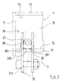
- Each of the suspension elements 3 comprises two parallel plates 30 also cut in the shape of C, that is to say each comprising a body 31 extended by on both sides by two curved parts 32 and 33 which form a central recess 34 and the ends of which, respectively 35 and 36, are opposite by being at a some distance from each other.
- the plates 30 are secured to a certain distance from each other via two pendulums 37, one connecting the ends 35, the other the ends 36 of plates 30, projecting into the recess 34.
- Each of the suspension elements 3 is assembled to the beam 1 by introducing the lower wing 12 thereof in the recess 34 of the plates 30, the core 10 passing between the ends 35 and 36, and the pendulums 37 resting on the inner face 15 of the wing 12.
- the positioning of a suspension element on the beam 1 is produced by means of a pin or the like, not shown, passing through the pendulums 37 through a hole 38, and passing through one of the holes 16 made in the extreme parts of the soul 10.
- the lower edges 39 of the pendulums 37 each have a central curved part 390, concentric to hole 38, and two end parts 391 planar tangents to the central part 390.
- Pendulums 37 and the space remaining between the body 31 of the plates 30 and the wing 12 allow a pivoting of the suspension elements on the wing 12 around of the pin, pivoting limited by the end parts 391 of the lower edges 39 of the pendulums 37.
- the bodies 31 of the plates 30 each include, substantially centrally, a hole 310 allowing the fixing between the plates 30 of a hook 311, visible on Figure 1, by means of a pin, or the like, 312.
- the device according to the invention is completed, for aesthetic and safety reasons, in pairs end plates 17, fixed to the ends of the beam 1 at by means of flanges, not shown, threaded in holes 18 drilled in the core 10 of the beam 1.
- the mounting of the lifting device according to the invention requires only drilling operations holes 14 and 16, and holes 18 for fixing the plates end 17.
- the device according to the invention comprises two attachment assemblies 5 and two suspension elements 3.
- Each of the attachment assemblies 5 differs from the attachment element 2 described above, in that the ring 22 is replaced by a plate 50, pierced in its upper region of an eye 51 for securing a sling 4 by means of a shackle 40, the eye 51 being offset towards the middle of beam 1, to allow better load distribution.
- suspension elements 3 are identical to those described above, in support of Figures 1 and 2.
Landscapes
- Engineering & Computer Science (AREA)
- Mechanical Engineering (AREA)
- Load-Engaging Elements For Cranes (AREA)
- Paper (AREA)
- Laser Surgery Devices (AREA)
Claims (5)
- Hebebalken, welcher einerseits einen Standard-Doppel-T-Träger (1) umfasst, bestehend aus zwei parallelen Flanschen (11, 12), die sich auf beiden Seiten eines Stegs (10) befinden, und andererseits ein Aufhängerelement (2) und zwei Aufhängungselemente (3), die an dem genannten Träger (1) befestigt sind. Die genannten Aufhängungsmittel (3) sind hierbei auf dem unteren Flansch (12) des genannten Trägers (1) aufgereiht und bestehen jeweils aus zwei parallelen Zwischenplatten (30), dadurch gekennzeichnet, dass die genannten Platten (30) aneinander geschweißt sind und jeweils in der Mitte eine T-förmige Aussparung (34) aufweisen, durch die der untere Flansch (12) und der Steg (10) des Trägers (1) hindurchpassen. Die feste Verbindung der beiden Platten (30) wird über zwei Schwingen (37) erreicht, die jeweils mit einem Loch (38) versehen sind, in das ein Stift oder Ähnliches gesteckt wird. Dieser geht außerdem durch eines der Löcher (16), die der Träger auf seiner Längsseite aufweist, durch den Steg (10) des Trägers hindurch. Die untere Kante (39) jeder der genannten Schwingen (37) berührt hierbei die Innenfläche (15) des unteren Flansches (12) und besteht aus einem konzentrisch zum Loch (38) der genannten Schwingen (37) gebogenen Mittelteil (390) und zwei flachen Endstücken (391), die tangential zum gebogenen Mittelstück (390) sind.
- Vorrichtung nach Anspruch 1, dadurch gekennzeichnet, dass das Aufhängerelement (2) auf den unteren Flansch (11) des Trägers (1) aufgeschoben wird und zu diesem Zweck aus zwei parallelen Platten (20) besteht, die jeweils in der Mitte eine in etwa T-förmige Aussparung (26) aufweisen, durch die der obere Flansch (11) und der Steg (10) des Trägers (1) hindurchpassen. Die genannten Platten (20) sind hierbei über eine Öse (22) und Zwischenstücke (21) fest miteinander verbunden. Letztere sind jeweils mit einem Loch (210) versehen, dessen Zweck darin besteht, dass ein Stift oder Ähnliches eingeführt wird, der außerdem durch ein Loch (14), das in seiner Mitte angebracht ist, durch den Steg (10) des Trägers (1) hindurchgeht.
- Vorrichtung nach Anspruch 1, dadurch gekennzeichnet, dass das Aufhängerelement aus zwei Einheiten (5) besteht, die auf den oberen Flansch (11) des Trägers (1) aufgeschoben sind und ein Aufhängen an zwei Anschlagmitteln (4) ermöglichen. Jede der genannten Einheiten (5) besteht hierbei aus zwei parallelen Platten (20), die jeweils in der Mitte eine T-förmige Aussparung (26) aufweisen und einerseits unten über zwei Zwischenstücke (21) fest miteinander verbunden sind, die jeweils mit einem Loch (210) versehen sind, in das ein Stift oder Ähnliches gesteckt werden kann, der außerdem durch den Steg (10) des Trägers (1) hindurchgeht, und andererseits oben über eine quer verlaufende Platte (50), die eine Aufhängeose (51) aufweist, die seitlich zur Mitte des Trägers (1) hin verschoben ist.
- Vorrichtung nach einem der vorhergehenden Ansprüche, dadurch gekennzeichnet, dass zwei Endplatten (17) an jeweils einem Ende des Trägers (1) mittels zweier Flansche fixiert werden, die in Löcher (18) im Steg (10) des Trägers (1) eingeführt werden.
- Vorrichtung nach einer der vorhergehenden Ansprüche, dadurch gekennzeichnet, dass die Platten (20, 30) der Aufhängungs- und Aufhängerelemente (2, 3, 5) C-förmig sind und aus einem Korpus (23, 31) bestehen, der jeweils auf beiden Seiten durch zwei gebogene Teile (24, 25, 32, 33) verlängert wird, die in der Mitte eine Aussparung bilden (26, 34) und deren Enden (27, 28, 35, 36) sich in kurzem Abstand gegenüber liegen.
Priority Applications (5)
| Application Number | Priority Date | Filing Date | Title |
|---|---|---|---|
| DE69611669T DE69611669T2 (de) | 1996-04-16 | 1996-04-16 | Hebebalken |
| AT96440029T ATE198863T1 (de) | 1996-04-16 | 1996-04-16 | Hebebalken |
| EP96440029A EP0802145B1 (de) | 1996-04-16 | 1996-04-16 | Hebebalken |
| ES96440029T ES2156266T3 (es) | 1996-04-16 | 1996-04-16 | Dispositivo de barra de elevacion. |
| US08/734,589 US5820184A (en) | 1996-04-16 | 1996-10-22 | Lifting rudder |
Applications Claiming Priority (1)
| Application Number | Priority Date | Filing Date | Title |
|---|---|---|---|
| EP96440029A EP0802145B1 (de) | 1996-04-16 | 1996-04-16 | Hebebalken |
Publications (2)
| Publication Number | Publication Date |
|---|---|
| EP0802145A1 EP0802145A1 (de) | 1997-10-22 |
| EP0802145B1 true EP0802145B1 (de) | 2001-01-24 |
Family
ID=8225405
Family Applications (1)
| Application Number | Title | Priority Date | Filing Date |
|---|---|---|---|
| EP96440029A Expired - Lifetime EP0802145B1 (de) | 1996-04-16 | 1996-04-16 | Hebebalken |
Country Status (5)
| Country | Link |
|---|---|
| US (1) | US5820184A (de) |
| EP (1) | EP0802145B1 (de) |
| AT (1) | ATE198863T1 (de) |
| DE (1) | DE69611669T2 (de) |
| ES (1) | ES2156266T3 (de) |
Cited By (2)
| Publication number | Priority date | Publication date | Assignee | Title |
|---|---|---|---|---|
| CN103277633A (zh) * | 2013-06-05 | 2013-09-04 | 山东赛瓦特动力设备有限公司 | 防音型柴油发电机组无吊架单点起吊装置 |
| CN104828688A (zh) * | 2015-01-09 | 2015-08-12 | 中国核工业二三建设有限公司 | 一种用于辅助移动起重机超起配重的工具及其使用方法 |
Families Citing this family (31)
| Publication number | Priority date | Publication date | Assignee | Title |
|---|---|---|---|---|
| US6053550A (en) * | 1997-05-07 | 2000-04-25 | Paterson; Bruce | Device for gripping and supporting articles |
| US6062620A (en) * | 1998-08-25 | 2000-05-16 | Eaton Corporation | Spreader bar |
| US7478852B1 (en) * | 2003-03-28 | 2009-01-20 | Durden P Trentis | Lifting beam |
| US20070296229A1 (en) * | 2006-06-23 | 2007-12-27 | The Stanley Works | Grappling system |
| US7597184B1 (en) | 2007-03-29 | 2009-10-06 | Honda Motor Co., Ltd. | Chain adjusting device for engine carriers |
| US8388033B2 (en) * | 2009-11-24 | 2013-03-05 | Alltec Lifting Systems Llc | Method and apparatus for hoisting objects using a modular lifting beam |
| US20110274531A1 (en) * | 2010-05-05 | 2011-11-10 | Over The Top Innovations | Apparatus and method for lifting and moving merchandise gondolas |
| DE102010022996B4 (de) * | 2010-06-08 | 2013-05-29 | Wader-Wittis Gmbh | Hubvorrichtung für Turmsegmente |
| CN102092625B (zh) * | 2010-12-24 | 2013-01-23 | 上海振华重工集团(南通)有限公司 | 通用吊装吊梁 |
| US8955894B2 (en) | 2011-07-18 | 2015-02-17 | Nc Services Group, Ltd. | Adjustable spreader bar system |
| CN102417137A (zh) * | 2011-12-07 | 2012-04-18 | 济南重工股份有限公司 | 热处理井式炉环类件吊装工具 |
| CA2798397C (en) | 2012-09-21 | 2017-03-07 | Pcl Industrial Management Inc. | Adjustable module lift assembly |
| US8622449B1 (en) * | 2012-10-02 | 2014-01-07 | Brad Stroh | Material handling system |
| EP2978705B1 (de) * | 2013-03-25 | 2017-03-15 | Pewag Austria GmbH | Ausgleichswippe für ein mehrsträngiges anschlagmittel |
| JP6198423B2 (ja) | 2013-03-27 | 2017-09-20 | 株式会社クボタ | 吊り上げ装置、吊り上げセット及び水処理設備 |
| CN103332592A (zh) * | 2013-06-27 | 2013-10-02 | 张家港凯航通力船用设备有限公司 | 一种舱盖大梁用翻身吊具 |
| CN105705453B (zh) * | 2013-11-08 | 2018-06-05 | 伊特里克公司 | 组装起重机吊杆的起重机吊杆段及组装起重机吊杆的方法 |
| CN103601066B (zh) * | 2013-11-19 | 2015-10-21 | 中冶天工集团有限公司 | 一种用于吊装位于隐蔽位置处设备的吊具及吊装方法 |
| CN103979407A (zh) * | 2014-05-19 | 2014-08-13 | 中国海洋石油总公司 | 法兰吊装器 |
| CN105383855B (zh) * | 2015-12-09 | 2017-11-07 | 贵州正合博莱金属制品有限公司 | 铝棒转运辅助装置用机箱 |
| CN105396726A (zh) * | 2015-12-23 | 2016-03-16 | 北京北方车辆集团有限公司 | 一种装甲车涂装悬挂吊具 |
| US20180362305A1 (en) * | 2016-04-27 | 2018-12-20 | Greenfield Products, Llc | Barge lid lifter system and method |
| CN105836599A (zh) * | 2016-06-23 | 2016-08-10 | 合肥市神雕起重机械有限公司 | 一种间距可调的平衡梁 |
| CN106090565A (zh) * | 2016-08-12 | 2016-11-09 | 佛山市章扬科技有限公司 | 用于无屏电视移动装置 |
| WO2020102036A1 (en) | 2018-11-15 | 2020-05-22 | B/A Products Co | Lifting device |
| US10633223B1 (en) * | 2018-11-27 | 2020-04-28 | Versabar, Inc. | Adjustable spreader bar |
| CN109969931A (zh) * | 2019-03-18 | 2019-07-05 | 广州城建职业学院 | 一种用于装配式建筑构件的多用途吊梁 |
| CN112079241A (zh) * | 2020-09-14 | 2020-12-15 | 大连船用柴油机有限公司 | 大功率低速柴油机辅助鼓风机吊装方法 |
| CN113636444A (zh) * | 2021-08-13 | 2021-11-12 | 中冶天工集团有限公司 | 一种可以调节不同重量的吊装方法及工具 |
| CN117509395A (zh) * | 2022-07-27 | 2024-02-06 | 中国航发商用航空发动机有限责任公司 | 吊装工具 |
| CN120057725B (zh) * | 2025-04-30 | 2025-07-15 | 中国水利水电第十工程局有限公司 | 一种钢结构厂房吊装施工装置 |
Family Cites Families (10)
| Publication number | Priority date | Publication date | Assignee | Title |
|---|---|---|---|---|
| US3343861A (en) * | 1965-12-10 | 1967-09-26 | United States Steel Corp | Lifting grapple for reels and the like |
| GB1159560A (en) * | 1967-05-06 | 1969-07-30 | Lifting & Engineering Services | Improvements in or relating to Lifting Beams |
| FR1562203A (de) * | 1968-02-20 | 1969-04-04 | ||
| US3561810A (en) * | 1968-09-23 | 1971-02-09 | Power Systems Inc | Lifting beam assembly |
| GB1540847A (en) * | 1976-09-10 | 1979-02-14 | Hartley Simon Ltd | Lifting beam |
| DE2811385C3 (de) * | 1978-03-16 | 1980-09-18 | Blohm + Voss Ag, 2000 Hamburg | Traverse |
| FR2541258A1 (fr) * | 1983-02-22 | 1984-08-24 | Simon Francois | Palonnier pour engin de levage et de manutention |
| US4626012A (en) * | 1984-09-19 | 1986-12-02 | Gary Weldele | Load positioner |
| US4973795A (en) * | 1989-11-09 | 1990-11-27 | Sharpe Robert F | Temporary transmission hot line crossarm and method of replacing transmission hot line crossarms |
| DE29505191U1 (de) * | 1995-03-29 | 1995-06-08 | Glumann, Karl, 09127 Chemnitz | Lasttraverse für stationäre und mobile Hubgeräte zum Bewegen von stabförmigen Gegenständen |
-
1996
- 1996-04-16 EP EP96440029A patent/EP0802145B1/de not_active Expired - Lifetime
- 1996-04-16 DE DE69611669T patent/DE69611669T2/de not_active Expired - Fee Related
- 1996-04-16 ES ES96440029T patent/ES2156266T3/es not_active Expired - Lifetime
- 1996-04-16 AT AT96440029T patent/ATE198863T1/de not_active IP Right Cessation
- 1996-10-22 US US08/734,589 patent/US5820184A/en not_active Expired - Fee Related
Cited By (2)
| Publication number | Priority date | Publication date | Assignee | Title |
|---|---|---|---|---|
| CN103277633A (zh) * | 2013-06-05 | 2013-09-04 | 山东赛瓦特动力设备有限公司 | 防音型柴油发电机组无吊架单点起吊装置 |
| CN104828688A (zh) * | 2015-01-09 | 2015-08-12 | 中国核工业二三建设有限公司 | 一种用于辅助移动起重机超起配重的工具及其使用方法 |
Also Published As
| Publication number | Publication date |
|---|---|
| DE69611669D1 (de) | 2001-03-01 |
| US5820184A (en) | 1998-10-13 |
| DE69611669T2 (de) | 2001-06-28 |
| ES2156266T3 (es) | 2001-06-16 |
| EP0802145A1 (de) | 1997-10-22 |
| ATE198863T1 (de) | 2001-02-15 |
Similar Documents
| Publication | Publication Date | Title |
|---|---|---|
| EP0802145B1 (de) | Hebebalken | |
| EP0635450B1 (de) | Verfahren und Vorrichtung zum Montieren der Ausleger von Turmkränen | |
| EP0296085B1 (de) | Seitenprofil für eine Ladebühne | |
| FR2756551A1 (fr) | Procede et dispositif pour le montage des tirants des fleches de grues a tour | |
| EP3481509B1 (de) | Vorrichtung für sicheren zugang zu einem geschlossenen raum, insbesondere einem mit seitenzugang begrenzten raum | |
| FR3021985A1 (fr) | Dispositif de raccordement a stabilite amelioree | |
| EP0290351B1 (de) | Zeltplanenträgerrahmen für einen leichten Unterstand | |
| FR2756265A1 (fr) | Tourillon de raccordement polyvalent pour palonnier de levage | |
| FR2458640A1 (fr) | Faux-plafond metallique | |
| FR2732323A1 (fr) | Blocs de lest pour grues et dispositif de fixation associe | |
| EP2275324B1 (de) | Ausgleichsgewichtssystem für einen Traktor, insbesondere einen landwirtschftlichen Traktor. | |
| FR2589506A1 (fr) | Dispositif de fixation d'une console pour circulation ou coffrage sur une paroi verticale d'un ouvrage en beton | |
| EP2762201B1 (de) | Mobile Verankerungsvorrichtung für Schiene | |
| EP0575269A1 (de) | Aufhängevorrichtung für Kabelkanäle | |
| FR2728238A3 (fr) | Conteneur-palette | |
| CH374580A (fr) | Dispositif d'attache d'un lien à un support | |
| FR2623241A1 (fr) | Dispositif d'ancrage d'une echelle sur un angle de poteau | |
| FR2580902A1 (fr) | Dispositif d'accrochage, notamment pour la suspension de quartiers de viande. | |
| FR3139323A1 (fr) | Dipositif permettant l’accroche d’un cable sur une palette pour permettre son chargement ou dechargement | |
| FR2897050A1 (fr) | Masse de controle d'un palan ou d'un pont roulant | |
| WO1989007174A1 (fr) | Dispositif d'accrochage d'un hauban sur un tablier en beton d'un pont, et pont equipe de tels dispositifs | |
| FR2581714A1 (fr) | Dispositif porteur a pince pour fixation a des profiles a ailes a faces paralleles ou obliques | |
| FR2637314A1 (fr) | Dispositif de securite a ligne de vie | |
| FR2651520A3 (fr) | Dispositif pour elargir une plate-forme d'echafaudage. | |
| FR2541258A1 (fr) | Palonnier pour engin de levage et de manutention |
Legal Events
| Date | Code | Title | Description |
|---|---|---|---|
| PUAI | Public reference made under article 153(3) epc to a published international application that has entered the european phase |
Free format text: ORIGINAL CODE: 0009012 |
|
| AK | Designated contracting states |
Kind code of ref document: A1 Designated state(s): AT BE CH DE ES FR GB GR IT LI NL SE |
|
| RIN1 | Information on inventor provided before grant (corrected) |
Inventor name: ECHENAY ALAIN |
|
| 17P | Request for examination filed |
Effective date: 19980323 |
|
| 17Q | First examination report despatched |
Effective date: 19990104 |
|
| GRAG | Despatch of communication of intention to grant |
Free format text: ORIGINAL CODE: EPIDOS AGRA |
|
| 17Q | First examination report despatched |
Effective date: 19990104 |
|
| GRAG | Despatch of communication of intention to grant |
Free format text: ORIGINAL CODE: EPIDOS AGRA |
|
| GRAH | Despatch of communication of intention to grant a patent |
Free format text: ORIGINAL CODE: EPIDOS IGRA |
|
| GRAH | Despatch of communication of intention to grant a patent |
Free format text: ORIGINAL CODE: EPIDOS IGRA |
|
| GRAA | (expected) grant |
Free format text: ORIGINAL CODE: 0009210 |
|
| AK | Designated contracting states |
Kind code of ref document: B1 Designated state(s): AT BE CH DE ES FR GB GR IT LI NL SE |
|
| PG25 | Lapsed in a contracting state [announced via postgrant information from national office to epo] |
Ref country code: SE Free format text: THE PATENT HAS BEEN ANNULLED BY A DECISION OF A NATIONAL AUTHORITY Effective date: 20010124 Ref country code: NL Free format text: LAPSE BECAUSE OF FAILURE TO SUBMIT A TRANSLATION OF THE DESCRIPTION OR TO PAY THE FEE WITHIN THE PRESCRIBED TIME-LIMIT Effective date: 20010124 Ref country code: GB Free format text: LAPSE BECAUSE OF FAILURE TO SUBMIT A TRANSLATION OF THE DESCRIPTION OR TO PAY THE FEE WITHIN THE PRESCRIBED TIME-LIMIT Effective date: 20010124 Ref country code: AT Free format text: LAPSE BECAUSE OF FAILURE TO SUBMIT A TRANSLATION OF THE DESCRIPTION OR TO PAY THE FEE WITHIN THE PRESCRIBED TIME-LIMIT Effective date: 20010124 |
|
| REF | Corresponds to: |
Ref document number: 198863 Country of ref document: AT Date of ref document: 20010215 Kind code of ref document: T |
|
| REG | Reference to a national code |
Ref country code: CH Ref legal event code: EP |
|
| REF | Corresponds to: |
Ref document number: 69611669 Country of ref document: DE Date of ref document: 20010301 |
|
| ITF | It: translation for a ep patent filed | ||
| PG25 | Lapsed in a contracting state [announced via postgrant information from national office to epo] |
Ref country code: GR Free format text: LAPSE BECAUSE OF FAILURE TO SUBMIT A TRANSLATION OF THE DESCRIPTION OR TO PAY THE FEE WITHIN THE PRESCRIBED TIME-LIMIT Effective date: 20010427 |
|
| PG25 | Lapsed in a contracting state [announced via postgrant information from national office to epo] |
Ref country code: LI Free format text: LAPSE BECAUSE OF NON-PAYMENT OF DUE FEES Effective date: 20010515 Ref country code: CH Free format text: LAPSE BECAUSE OF NON-PAYMENT OF DUE FEES Effective date: 20010515 |
|
| REG | Reference to a national code |
Ref country code: ES Ref legal event code: FG2A Ref document number: 2156266 Country of ref document: ES Kind code of ref document: T3 |
|
| NLV1 | Nl: lapsed or annulled due to failure to fulfill the requirements of art. 29p and 29m of the patents act | ||
| GBV | Gb: ep patent (uk) treated as always having been void in accordance with gb section 77(7)/1977 [no translation filed] |
Effective date: 20010124 |
|
| PLBE | No opposition filed within time limit |
Free format text: ORIGINAL CODE: 0009261 |
|
| STAA | Information on the status of an ep patent application or granted ep patent |
Free format text: STATUS: NO OPPOSITION FILED WITHIN TIME LIMIT |
|
| REG | Reference to a national code |
Ref country code: CH Ref legal event code: PL |
|
| 26N | No opposition filed | ||
| PG25 | Lapsed in a contracting state [announced via postgrant information from national office to epo] |
Ref country code: DE Free format text: LAPSE BECAUSE OF NON-PAYMENT OF DUE FEES Effective date: 20020201 |
|
| PGFP | Annual fee paid to national office [announced via postgrant information from national office to epo] |
Ref country code: FR Payment date: 20100420 Year of fee payment: 15 Ref country code: ES Payment date: 20100414 Year of fee payment: 15 |
|
| PGFP | Annual fee paid to national office [announced via postgrant information from national office to epo] |
Ref country code: BE Payment date: 20100503 Year of fee payment: 15 |
|
| PG25 | Lapsed in a contracting state [announced via postgrant information from national office to epo] |
Ref country code: IT Free format text: LAPSE BECAUSE OF NON-PAYMENT OF DUE FEES Effective date: 20100416 |
|
| PGFP | Annual fee paid to national office [announced via postgrant information from national office to epo] |
Ref country code: IT Payment date: 20100429 Year of fee payment: 15 |
|
| PGRI | Patent reinstated in contracting state [announced from national office to epo] |
Ref country code: IT Effective date: 20110616 |
|
| BERE | Be: lapsed |
Owner name: S.A. *TOPAL INDUSTRIES Effective date: 20110430 |
|
| REG | Reference to a national code |
Ref country code: FR Ref legal event code: ST Effective date: 20111230 |
|
| PG25 | Lapsed in a contracting state [announced via postgrant information from national office to epo] |
Ref country code: BE Free format text: LAPSE BECAUSE OF NON-PAYMENT OF DUE FEES Effective date: 20110430 Ref country code: FR Free format text: LAPSE BECAUSE OF NON-PAYMENT OF DUE FEES Effective date: 20110502 |
|
| PGRI | Patent reinstated in contracting state [announced from national office to epo] |
Ref country code: IT Effective date: 20110616 |
|
| REG | Reference to a national code |
Ref country code: ES Ref legal event code: FD2A Effective date: 20120524 |
|
| PG25 | Lapsed in a contracting state [announced via postgrant information from national office to epo] |
Ref country code: ES Free format text: LAPSE BECAUSE OF NON-PAYMENT OF DUE FEES Effective date: 20110417 |