EP0802148A1 - Train de roulement, en particulier pour palan à chaîn, appareil de manutention de charge et/ou câble de remorquage - Google Patents
Train de roulement, en particulier pour palan à chaîn, appareil de manutention de charge et/ou câble de remorquage Download PDFInfo
- Publication number
- EP0802148A1 EP0802148A1 EP97250124A EP97250124A EP0802148A1 EP 0802148 A1 EP0802148 A1 EP 0802148A1 EP 97250124 A EP97250124 A EP 97250124A EP 97250124 A EP97250124 A EP 97250124A EP 0802148 A1 EP0802148 A1 EP 0802148A1
- Authority
- EP
- European Patent Office
- Prior art keywords
- rail
- running gear
- wheels
- frame
- gear according
- Prior art date
- Legal status (The legal status is an assumption and is not a legal conclusion. Google has not performed a legal analysis and makes no representation as to the accuracy of the status listed.)
- Granted
Links
Images




Classifications
-
- B—PERFORMING OPERATIONS; TRANSPORTING
- B66—HOISTING; LIFTING; HAULING
- B66C—CRANES; LOAD-ENGAGING ELEMENTS OR DEVICES FOR CRANES, CAPSTANS, WINCHES, OR TACKLES
- B66C9/00—Travelling gear incorporated in or fitted to trolleys or cranes
- B66C9/06—Travelling gear incorporated in or fitted to trolleys or cranes for more than one rail gauge
-
- B—PERFORMING OPERATIONS; TRANSPORTING
- B66—HOISTING; LIFTING; HAULING
- B66C—CRANES; LOAD-ENGAGING ELEMENTS OR DEVICES FOR CRANES, CAPSTANS, WINCHES, OR TACKLES
- B66C11/00—Trolleys or crabs, e.g. operating above runways
- B66C11/02—Trolleys or crabs, e.g. operating above runways with operating gear or operator's cabin suspended, or laterally offset, from runway or track
- B66C11/04—Underhung trolleys
- B66C11/06—Underhung trolleys running on monorails
Definitions
- the invention relates to a trolley, in particular for chain hoists, load suspension devices and / or trailing cables, which comprises a cross-section of the rail consisting of flange and web parts, with opposing running wheels and guide rollers which are rotatably mounted in side-mounted wheel carriers connected below the cross-section of the rail, with at least one the wheel carrier is provided with a load suspension device.
- a trolley with a hoist with a short overall height which has running wheels running on the lower flange of a rail and mounted on a support frame.
- One of the wheels of this lower flange trolley is driven and mounted on a rocker which is pivotally arranged on the support frame.
- a friction wheel is arranged on the rocker arm, which rests on the lower flange of the rocker arm from below and is connected to the driven impeller in terms of drive.
- An adjustable eccentric provided ensures that all impellers rest evenly on the lower flange.
- This trolley proves to be advantageous for applications in which high frictional reinforcement is required; a disadvantage is the very high installation effort when mounting the trolley on the carrier.
- these trolleys are not suitable for different web thicknesses and flange widths.
- a trolley with at least one running wheel is known from DE 30 30 929 A1, which is provided with laterally arranged guide rollers for perfect guiding on the rail support, said guide rollers abutting one another on vertical guide surfaces of a rail support.
- the upper guide rollers together with the lower guide rollers effectively prevent the trolley from tilting on the rail support and the front guide rollers together with the rear guide rollers ensure that the trolley is guided properly in the longitudinal direction of the rail support.
- It is also a disadvantage of this trolley despite the small number of individual parts, that the assembly of the trolley on the carrier is relatively complex.
- This trolley also has a small space of about 1 mm between the guide surfaces and the guide rollers to compensate for tolerances, which means that the parallel running of the rollers is not always guaranteed.
- a very good parallel running of the rollers must be ensured in and outside of bends.
- the running gear should run stably on the carrier rail even with a swinging load, so it should not tend to pitch movements and sideways swinging of the running gear.
- the invention provides that wheel carrier arms which can be pivoted in or out in pairs are pivotably mounted about an axis extending in the direction of the rail and extending below the rail cross-section, the load on at least one of the wheel carrier arms at the level or below the joint formed in each case of the wheel carrier arms connected to one another attacks and the Wheel carrier arms are kept pivoted in on the cross-section of the running rail to a limited extent by a closing torque resulting from the load from the guide rollers resting on both sides of the web.
- the undercarriage according to the invention makes it possible to hang it up in the preassembled state with a few hand movements on a travel rail with a corresponding travel rail cross section, the running gear comprising the travel rail cross section consisting of flange and web parts.
- the (automatically) backlash-free guide rollers which rest on both sides of the web, ensure that the rollers run evenly in parallel, which in turn means that the rolling resistance and thus wear on the rollers are low; the guide rollers are also subject to very little wear in the solution according to the invention. Low wear is associated with low driving resistance, so that the undercarriage can be moved with relatively little effort.
- the undercarriage pivoted in by the load proves to be very advantageous, especially when cornering, since the parallel running of the rollers is ensured even when cornering.
- the constantly attached guide rollers ensure stable guidance of the undercarriage even when the load is swinging. Changes in diameter of the wheels and the guide rollers due to unavoidable abrasion is compensated for in the chassis according to the invention within a large tolerance range in that the chassis automatically adapts to the rail.
- the wheel carrier arms are each designed as a frame pivotably mounted on the axle, each of which accommodates at least two opposing wheels in the center and pairs of horizontal guide rollers in front and behind the wheels, the wheels being located Support on the flange parts and press the horizontal guide roller pairs against the web of the rail cross section. If only two wheels are used, the result is particularly good maneuverability in curves.
- the stability of the undercarriage is particularly great when the frame with the wheels and with the horizontal guide roller pairs is so far above the the respective flange part of the cross-section of the rails can be swiveled in so that the wheels run close to the web.
- the frames are designed in such a way that there is a driving play between the flange part running surface of the rail cross section and the directly opposite surface of the frame. This can be, for example, one millimeter.
- the driving game ensures that the load and the drive do not fall if the wheel breaks.
- the chassis can then be used as a "suspension claw", for example when defective or worn wheels have to be replaced.
- a favorable size with few components and low costs can be achieved if the joint formed below the cross-section of the rail is at the same time a suspension device for the load to be attached.
- the adjustment of the undercarriage to different web thicknesses can advantageously also take place in that the angular position between the frames for the running wheels or for the guide rollers can be adjusted by means of adjustable spacing means.
- a set screw can be used as a sling. In this embodiment, part of the closing force resulting from the load is absorbed within the chassis itself.
- Two different angular positions of the frames for adaptation to different flange inclinations can be achieved very simply by providing two bores in the frame in the region of the joint, two different angular positions of the frames being adjustable by means of a pair of holes and a screw penetrating both frames. This makes it possible to cover all standard cases that occur with a cylindrical standard roll.
- a compact and robust undercarriage with simple drive attachment results if an impeller is directly motor-driven with two impellers.
- the drive can be carried out largely maintenance-free.
- the running stability of the undercarriage is improved in that the wheel or wheels of one frame are offset from one another in the direction of travel relative to the wheel of the other frame.
- the invention proposes that the guide rollers protrude from the frame in the direction of travel. This means that no additional plastic or rubber buffers are required.
- Identical frames can be used for the right and left frames if the ends of the two frames that form the joint are fork-shaped and axially offset on the axis and if both ends of the frame are articulated with a central screw.
- the chassis is also compact in that the load is supported on the screw connection by means of a suspension bracket.
- the suspension bracket can be provided with a cross hole, so that the suspension of the load can be fastened rotated by 90 ° with little effort.
- a connection, in particular secured against rotation, is achieved in that a hexagon socket recess is incorporated into the frame ends for a hexagon screw.
- a very simple fixation results when the snap lock is formed by a spring-type locking element with bolts, the bolts protruding through a free hole in each frame and snapped into a recess in the opposite frame.
- a very even load distribution is achieved if the load acts on at least one of the frames in the center of the cross-section of the running rail.
- a chassis is shown in front view, which comprises a rail 1, which consists of flange parts 2 and a web 3.
- the undercarriage itself has two wheel carrier arms 4a, 4b, which are designed as frames 5a, 5b.
- the frames 5a, 5b are mounted so as to be pivotable about an axis 6 which extends in the direction of the running rail 1 and runs below the cross-section of the running rail, which enables the frames 5a, 5b to be pivoted open or closed.
- Fig. 1 shows that in the upper region of the frame 5a, 5b a pair of opposing wheels 7 are arranged, the axes of rotation of which are horizontal and are supported in the frame 5a, 5b.
- the frames 5a, 5b take in addition to the centrally arranged in the frame 5a, 5b wheels 7 in front and behind the wheels 7 arranged horizontal guide roller pairs, which consist of guide rollers 9, which are supported in the frame 5a, 5b in a vertically rotatably mounted manner. While the running wheels 7 are supported on the lower flange parts 2, the guide rollers 9 rest in pairs on the web 3 of the running rail 1. 1 shows that the frames 5a, 5b can be pivoted so far over the respective flange part 2 of the rail cross section of the rail 1 that the running wheels 7 move directly near the web of the web 3.
- the load on the load hook 11 engages the axis 6; the joint formed below the running rail 1 is at the same time a suspension means for the load to be suspended.
- a suspension means for the load to be suspended are also conceivable, but it is crucial that the load acts on the height or below the joint 10 of the frames 5a, 5b interconnected by the joint on at least one of the frames 5a or 5b in the center of the cross-section of the rail.
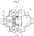
- FIG. 2 shows a partially sectioned plan view of the undercarriage according to FIG. 1 (the travel rail is omitted in FIG. 2).
- FIG. 3 shows a front view of the undercarriage according to FIG. 1, in which the angular position between the frames 5a, 5b for the running wheels 7 and for the guide rollers 9 can be penetrated by means of an adjustable spacing means 12.
- the spacer 12 shown in FIG. 3 is a stop 13 with an adjusting screw. In addition to the adjustment of the angular position between the frames 5a, 5b, the stop 13 causes the closing torque resulting from the load to be absorbed essentially within the chassis itself.
- a driving game 15 is present between the flange part tread 8 of the travel rail 1 and the surface 14 directly opposite this.
- the driving play 15 is approximately 1 mm and prevents the undercarriage from falling in the event of a wheel break, in particular thereby preventing shear from falling.
- the driving game 15 also makes it possible to use the undercarriage as a suspension claw, which enables the wheels to be replaced easily, for example by means of a support plate inserted into the gap in the driving game 15.
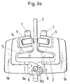
- the frames 5a, 5b are provided in the region of the joint 10 with two bores 16, 16a parallel to the axis 6 (Fig. 1 and Fig. 3a), which enables a second angular position of the frames 5a, 5b by displacing the axis 6, so that the running gear can be optimally adjusted for a second flange inclination.
- Fig. 3a a chassis is shown, in which the axle 6 is inserted into the second bore 16, which - as can be clearly seen in Fig. 3a - allows an optimal adaptation to the inclined flange inclination of the rail 1 in Fig. 3a.
- impeller 7 of a frame 5a or 5b offset relative to the impeller 7 of the other frame 5b or 5a in the direction of travel. This measure can also be used to increase the positional stability during load transport.
- Fig. 2 also shows that the guide rollers 7 protrude from the frame 5a, 5b in the direction of travel and form a buffer to an end stop (not shown), whereby no rubber or plastic buffers are additionally required.
- the two fork-shaped (see FIGS. 1 and 3) frames 5a, 5b are of identical design and are arranged with their ends axially offset on the axis 6.
- a hexagonal recess 17 is worked into the frame ends of the frame 5a, 5b articulated to one another with a central screw connection by means of a screw 6a designed as a hexagon screw.
- the load is supported on the screw 6a via a suspension bracket.
- a snap lock 19 can be seen as a safeguard against inadvertent opening of the undercarriage when relieved, which latches automatically when closed, but can only be released by hand when opened.
- the snap lock 19 is formed by a resilient locking element 20 and a bolt 21.
- the bolt 21 protrudes - penetrating a bore 22 of the outer frame 5a - in the operating position into a recess 23 of the inner frame 5b and is held in this.
- the ratio of the vertical distance between the axes of the impellers 7 'and the horizontal distance of the impellers 7 from the axis 6 (swivel axis) is greater than 3 and less than 10.
Landscapes
- Engineering & Computer Science (AREA)
- Mechanical Engineering (AREA)
- Carriers, Traveling Bodies, And Overhead Traveling Cranes (AREA)
- Chain Conveyers (AREA)
- Framework For Endless Conveyors (AREA)
Applications Claiming Priority (4)
| Application Number | Priority Date | Filing Date | Title |
|---|---|---|---|
| DE19617119 | 1996-04-19 | ||
| DE19617119 | 1996-04-19 | ||
| DE19620145 | 1996-05-09 | ||
| DE19620145A DE19620145C2 (de) | 1996-04-19 | 1996-05-09 | Fahrwerk, insbesondere für Kettenzüge, Lastaufnahmemittel und/oder Schleppkabel |
Publications (2)
| Publication Number | Publication Date |
|---|---|
| EP0802148A1 true EP0802148A1 (fr) | 1997-10-22 |
| EP0802148B1 EP0802148B1 (fr) | 2001-06-20 |
Family
ID=26025230
Family Applications (1)
| Application Number | Title | Priority Date | Filing Date |
|---|---|---|---|
| EP97250124A Expired - Lifetime EP0802148B1 (fr) | 1996-04-19 | 1997-04-18 | Train de roulement, en particulier pour palan à chaín, appareil de manutention de charge et/ou câble de remorquage |
Country Status (4)
| Country | Link |
|---|---|
| US (1) | US5881650A (fr) |
| EP (1) | EP0802148B1 (fr) |
| JP (1) | JP3910257B2 (fr) |
| ES (1) | ES2157525T3 (fr) |
Cited By (4)
| Publication number | Priority date | Publication date | Assignee | Title |
|---|---|---|---|---|
| FR2777270A1 (fr) * | 1998-04-08 | 1999-10-15 | Mannesmann Ag | Dispositif de roulement, en particulier pour des dispositifs de levage |
| CN110395659A (zh) * | 2019-06-28 | 2019-11-01 | 中国一冶集团有限公司 | 浸出槽侧部大口径钢衬管安装设备及安装方法 |
| EP4029821A1 (fr) * | 2021-01-19 | 2022-07-20 | Fives Conveying | Chariot de convoyage aerien de charges |
| DE102023207015A1 (de) * | 2023-07-24 | 2025-01-30 | Gerrit Pies | Laufwagen für ein schienengeführtes Fördersystem |
Families Citing this family (12)
| Publication number | Priority date | Publication date | Assignee | Title |
|---|---|---|---|---|
| US8393055B2 (en) * | 1997-05-21 | 2013-03-12 | Ted Gower | Track mount for flexible impact resistant enclosure |
| CA2513283C (fr) * | 2005-07-15 | 2012-07-24 | Unique Concepts Ltd. | Dispositif a chariot et a rail utilise pour la protection contre les chutes et applications similaires |
| JP2008050165A (ja) * | 2006-07-28 | 2008-03-06 | Three H:Kk | トロリー |
| DE102006039812B3 (de) * | 2006-08-25 | 2008-02-21 | Demag Cranes & Components Gmbh | Fahrwerk, insbesondere Einschienenunterflansch-Fahrwerk für Hebezeuge |
| EP3424774B1 (fr) * | 2013-11-06 | 2023-02-22 | Honda Motor Co., Ltd. | Appareil de charge de contact avec bras de charge et système de charge de contact pour véhicule électrique |
| CN104340863B (zh) * | 2014-10-11 | 2017-03-01 | 华电重工股份有限公司 | 一种穿越式双小车系统及穿越式多小车系统 |
| WO2018102159A1 (fr) * | 2016-11-29 | 2018-06-07 | Regal Beloit America, Inc. | Ensemble chariot pour un système de transport |
| KR101947512B1 (ko) * | 2018-10-10 | 2019-05-21 | 주식회사 인덕 | 이동식 어셈블리형 oltc 인양장치 |
| KR102301077B1 (ko) * | 2019-11-26 | 2021-09-14 | (주)정우프랜트 | 중량물 주행장치 |
| CN113636455B (zh) * | 2021-07-21 | 2023-11-21 | 上海外高桥造船有限公司 | 一种可替换式电驱防爆吊运系统 |
| CN113829325B (zh) * | 2021-10-11 | 2025-04-22 | 深圳市朗驰欣创科技股份有限公司 | 一种挂轨式机器人的行走机构和轨道机器人 |
| US12545524B2 (en) | 2023-12-18 | 2026-02-10 | Lewco, Inc. | Vertical conveying system |
Citations (8)
| Publication number | Priority date | Publication date | Assignee | Title |
|---|---|---|---|---|
| US1005452A (en) * | 1910-03-03 | 1911-10-10 | Edward Y Moore | Trolley-hoist. |
| DE1939084U (de) * | 1966-03-16 | 1966-05-18 | Hueser & Weber K G | Laufkatze. |
| DE6915892U (de) * | 1969-04-16 | 1969-10-30 | Bernhard Veltmann | Klappbare kleinlaufkatze fuer einschienenhaengebahn |
| DE2353622A1 (de) * | 1973-10-26 | 1975-05-07 | Mannesmann Ag | Haengebahnfahrzeug |
| FR2318099A1 (fr) * | 1975-07-15 | 1977-02-11 | Defleur Ets | Chariot porte-palan ouvrant |
| DE4109971A1 (de) * | 1991-03-22 | 1992-09-24 | Mannesmann Ag | Einschienenbahn-unterflansch-fahrwerk |
| US5445080A (en) * | 1993-10-21 | 1995-08-29 | Austin; Robert | Free ranging monotrack sortveyor with selectively lockable article carrying tilt tray |
| DE19507880A1 (de) * | 1994-03-23 | 1995-09-28 | Remmert Friedrich Gmbh | Kurvengängiges Regalförderzeug |
Family Cites Families (17)
| Publication number | Priority date | Publication date | Assignee | Title |
|---|---|---|---|---|
| NL12819C (fr) * | ||||
| US911221A (en) * | 1907-01-24 | 1909-02-02 | Ross J Ellsworth | Detachable conveying-trolley. |
| US1151226A (en) * | 1915-06-21 | 1915-08-24 | Curtis & Company Mfg Company | Trolley. |
| US1646217A (en) * | 1925-11-19 | 1927-10-18 | Yale & Towne Mfg Co | Trolley construction |
| DE494451C (de) * | 1927-11-29 | 1930-03-22 | Fritz Doehle | Laufkatze |
| US2611326A (en) * | 1949-09-12 | 1952-09-23 | Cosby D P Smallpeice | Trolley |
| US2645187A (en) * | 1951-07-21 | 1953-07-14 | Guadagna Joseph | Removable snatch roller |
| US2744472A (en) * | 1953-03-24 | 1956-05-08 | Albina Engine & Machine Works | I-beam roller |
| DE1927583C3 (de) * | 1969-05-30 | 1974-06-27 | Gerald 2000 Hamburg Brettel | Vorrichtung zum natürlichen Trocknen von Furnieren od.dgl |
| DE1939084A1 (de) * | 1969-07-31 | 1971-12-09 | Rauch Fa Constantin | Hydrostatische Lagerentlastung bei Axialkolbenmaschinen |
| US3774548A (en) * | 1971-01-13 | 1973-11-27 | A Borst | Gripping locomotive for suspended railway |
| JPS529190A (en) * | 1975-07-14 | 1977-01-24 | Masaharu Matsuo | Conveyer means for driving waste removing claws |
| US4271927A (en) * | 1979-06-04 | 1981-06-09 | Riggers (Steeplejacks) Limited | Inspection or maintenance cradle |
| DE3030929C2 (de) * | 1980-08-16 | 1983-01-05 | Mannesmann AG, 4000 Düsseldorf | Laufkatze |
| IT8521925U1 (it) * | 1985-05-23 | 1986-11-23 | Fata European Group Spa | Apparecchiatura perfezionata per il trasporto aereo di carichi pesanti su monorotaia |
| DE4209565C2 (de) * | 1992-03-20 | 1995-01-19 | Mannesmann Ag | Laufkatze, insbesondere Einschienenkatze mit kurzer Bauhöhe |
| US5664502A (en) * | 1994-07-27 | 1997-09-09 | Westinghouse Electric Corporation | Wheel assembly capable of maintaining engagement with a rail having an uneven portion therein |
-
1997
- 1997-04-16 US US08/843,698 patent/US5881650A/en not_active Expired - Lifetime
- 1997-04-16 JP JP11431697A patent/JP3910257B2/ja not_active Expired - Fee Related
- 1997-04-18 ES ES97250124T patent/ES2157525T3/es not_active Expired - Lifetime
- 1997-04-18 EP EP97250124A patent/EP0802148B1/fr not_active Expired - Lifetime
Patent Citations (8)
| Publication number | Priority date | Publication date | Assignee | Title |
|---|---|---|---|---|
| US1005452A (en) * | 1910-03-03 | 1911-10-10 | Edward Y Moore | Trolley-hoist. |
| DE1939084U (de) * | 1966-03-16 | 1966-05-18 | Hueser & Weber K G | Laufkatze. |
| DE6915892U (de) * | 1969-04-16 | 1969-10-30 | Bernhard Veltmann | Klappbare kleinlaufkatze fuer einschienenhaengebahn |
| DE2353622A1 (de) * | 1973-10-26 | 1975-05-07 | Mannesmann Ag | Haengebahnfahrzeug |
| FR2318099A1 (fr) * | 1975-07-15 | 1977-02-11 | Defleur Ets | Chariot porte-palan ouvrant |
| DE4109971A1 (de) * | 1991-03-22 | 1992-09-24 | Mannesmann Ag | Einschienenbahn-unterflansch-fahrwerk |
| US5445080A (en) * | 1993-10-21 | 1995-08-29 | Austin; Robert | Free ranging monotrack sortveyor with selectively lockable article carrying tilt tray |
| DE19507880A1 (de) * | 1994-03-23 | 1995-09-28 | Remmert Friedrich Gmbh | Kurvengängiges Regalförderzeug |
Cited By (5)
| Publication number | Priority date | Publication date | Assignee | Title |
|---|---|---|---|---|
| FR2777270A1 (fr) * | 1998-04-08 | 1999-10-15 | Mannesmann Ag | Dispositif de roulement, en particulier pour des dispositifs de levage |
| CN110395659A (zh) * | 2019-06-28 | 2019-11-01 | 中国一冶集团有限公司 | 浸出槽侧部大口径钢衬管安装设备及安装方法 |
| EP4029821A1 (fr) * | 2021-01-19 | 2022-07-20 | Fives Conveying | Chariot de convoyage aerien de charges |
| FR3118959A1 (fr) * | 2021-01-19 | 2022-07-22 | Fives Conveying | Chariot de convoyage aerien de charges |
| DE102023207015A1 (de) * | 2023-07-24 | 2025-01-30 | Gerrit Pies | Laufwagen für ein schienengeführtes Fördersystem |
Also Published As
| Publication number | Publication date |
|---|---|
| EP0802148B1 (fr) | 2001-06-20 |
| JPH1067486A (ja) | 1998-03-10 |
| US5881650A (en) | 1999-03-16 |
| JP3910257B2 (ja) | 2007-04-25 |
| ES2157525T3 (es) | 2001-08-16 |
Similar Documents
| Publication | Publication Date | Title |
|---|---|---|
| EP0845435B1 (fr) | Train de roulement pour un appareil de levage | |
| EP0802148B1 (fr) | Train de roulement, en particulier pour palan à chaín, appareil de manutention de charge et/ou câble de remorquage | |
| EP1086868B1 (fr) | Balancier à double effet pour supports de transporteurs aériens monocable, notamment de télésièges et de télécabines | |
| EP0936119B1 (fr) | Porte pivotante coulissante pour véhicules | |
| DE19713500C1 (de) | Fahrwerk einer schienenverfahrbaren Hebevorrichtung | |
| EP0802149B1 (fr) | Train de roulement, en particulier pour palan à châine, appareil de manutention de charge et/ou câble de remorquage | |
| DE3405994C2 (de) | Seilzug-Fensterheber | |
| EP1227022B1 (fr) | Téléphérique | |
| EP0802147B1 (fr) | Train de roulement, en particulier pour palan à chaíne et/ou câble de remorquage | |
| DE19620145C2 (de) | Fahrwerk, insbesondere für Kettenzüge, Lastaufnahmemittel und/oder Schleppkabel | |
| WO2016165822A1 (fr) | Dispositif de liaison, chariot de transport et système de transport | |
| DE19828336B4 (de) | Laufwerk | |
| DE19816576C2 (de) | Fahrwerk, insbesondere für Hubwerke | |
| EP1549801B1 (fr) | Liaison articulee destinee a des joints de rails de roulement profiles | |
| EP0679788A1 (fr) | Chariot ainsi qu'ensemble coulissant et rail | |
| DE19620150C2 (de) | Fahrwerk, insbesondere für Kettenzüge, Lastaufnahmemittel und/oder Schleppkabel | |
| EP1298271A2 (fr) | Chariot pour une ferrure pour portes ou fenêtres à soulèvement et coulissement et ferrure avec un tel chariot | |
| DE202005004059U1 (de) | Führungssystem für eine Schiebetür | |
| DE3206761A1 (de) | Gelenkfahrzeug | |
| EP0634541B1 (fr) | Chariot de roulement | |
| AT405732B (de) | Hängebahn | |
| DE19748601C2 (de) | Schwenklager für den Ausleger eines Säulenschwenkkranes | |
| DE9418720U1 (de) | Wagenheber für Kfz. | |
| DE19755456C1 (de) | Seiltrieb eines Hebezeuges | |
| CH683516A5 (de) | Sicherheitsvorrichtung für einen Laufwagen an einer Seilkran-Anlage. |
Legal Events
| Date | Code | Title | Description |
|---|---|---|---|
| PUAI | Public reference made under article 153(3) epc to a published international application that has entered the european phase |
Free format text: ORIGINAL CODE: 0009012 |
|
| AK | Designated contracting states |
Kind code of ref document: A1 Designated state(s): DE ES FR GB IT |
|
| 17P | Request for examination filed |
Effective date: 19980318 |
|
| GRAG | Despatch of communication of intention to grant |
Free format text: ORIGINAL CODE: EPIDOS AGRA |
|
| 17Q | First examination report despatched |
Effective date: 20000717 |
|
| GRAG | Despatch of communication of intention to grant |
Free format text: ORIGINAL CODE: EPIDOS AGRA |
|
| GRAH | Despatch of communication of intention to grant a patent |
Free format text: ORIGINAL CODE: EPIDOS IGRA |
|
| GRAH | Despatch of communication of intention to grant a patent |
Free format text: ORIGINAL CODE: EPIDOS IGRA |
|
| GRAA | (expected) grant |
Free format text: ORIGINAL CODE: 0009210 |
|
| AK | Designated contracting states |
Kind code of ref document: B1 Designated state(s): DE ES FR GB IT |
|
| GBT | Gb: translation of ep patent filed (gb section 77(6)(a)/1977) |
Effective date: 20010621 |
|
| REF | Corresponds to: |
Ref document number: 59703843 Country of ref document: DE Date of ref document: 20010726 |
|
| REG | Reference to a national code |
Ref country code: ES Ref legal event code: FG2A Ref document number: 2157525 Country of ref document: ES Kind code of ref document: T3 |
|
| ITF | It: translation for a ep patent filed | ||
| ET | Fr: translation filed | ||
| REG | Reference to a national code |
Ref country code: GB Ref legal event code: IF02 |
|
| PLBE | No opposition filed within time limit |
Free format text: ORIGINAL CODE: 0009261 |
|
| STAA | Information on the status of an ep patent application or granted ep patent |
Free format text: STATUS: NO OPPOSITION FILED WITHIN TIME LIMIT |
|
| 26N | No opposition filed | ||
| REG | Reference to a national code |
Ref country code: GB Ref legal event code: 732E |
|
| REG | Reference to a national code |
Ref country code: FR Ref legal event code: TP |
|
| PGFP | Annual fee paid to national office [announced via postgrant information from national office to epo] |
Ref country code: GB Payment date: 20140422 Year of fee payment: 18 |
|
| PGFP | Annual fee paid to national office [announced via postgrant information from national office to epo] |
Ref country code: ES Payment date: 20140428 Year of fee payment: 18 Ref country code: DE Payment date: 20140418 Year of fee payment: 18 Ref country code: FR Payment date: 20140422 Year of fee payment: 18 Ref country code: IT Payment date: 20140430 Year of fee payment: 18 |
|
| REG | Reference to a national code |
Ref country code: DE Ref legal event code: R119 Ref document number: 59703843 Country of ref document: DE |
|
| GBPC | Gb: european patent ceased through non-payment of renewal fee |
Effective date: 20150418 |
|
| PG25 | Lapsed in a contracting state [announced via postgrant information from national office to epo] |
Ref country code: DE Free format text: LAPSE BECAUSE OF NON-PAYMENT OF DUE FEES Effective date: 20151103 Ref country code: IT Free format text: LAPSE BECAUSE OF NON-PAYMENT OF DUE FEES Effective date: 20150418 Ref country code: GB Free format text: LAPSE BECAUSE OF NON-PAYMENT OF DUE FEES Effective date: 20150418 |
|
| REG | Reference to a national code |
Ref country code: FR Ref legal event code: ST Effective date: 20151231 |
|
| PG25 | Lapsed in a contracting state [announced via postgrant information from national office to epo] |
Ref country code: FR Free format text: LAPSE BECAUSE OF NON-PAYMENT OF DUE FEES Effective date: 20150430 |
|
| REG | Reference to a national code |
Ref country code: ES Ref legal event code: FD2A Effective date: 20160526 |
|
| PG25 | Lapsed in a contracting state [announced via postgrant information from national office to epo] |
Ref country code: ES Free format text: LAPSE BECAUSE OF NON-PAYMENT OF DUE FEES Effective date: 20150419 |