EP0802610A2 - Motopompe pour hautes températures et procédé pour son fonctionnement - Google Patents
Motopompe pour hautes températures et procédé pour son fonctionnement Download PDFInfo
- Publication number
- EP0802610A2 EP0802610A2 EP97104643A EP97104643A EP0802610A2 EP 0802610 A2 EP0802610 A2 EP 0802610A2 EP 97104643 A EP97104643 A EP 97104643A EP 97104643 A EP97104643 A EP 97104643A EP 0802610 A2 EP0802610 A2 EP 0802610A2
- Authority
- EP
- European Patent Office
- Prior art keywords
- coolant
- temperature
- motor
- pump
- stator
- Prior art date
- Legal status (The legal status is an assumption and is not a legal conclusion. Google has not performed a legal analysis and makes no representation as to the accuracy of the status listed.)
- Withdrawn
Links
- 238000000034 method Methods 0.000 title claims abstract description 34
- 239000002826 coolant Substances 0.000 claims abstract description 119
- 238000001816 cooling Methods 0.000 claims abstract description 12
- 239000007788 liquid Substances 0.000 claims description 35
- 238000005086 pumping Methods 0.000 claims description 10
- 238000001704 evaporation Methods 0.000 claims description 5
- 230000008020 evaporation Effects 0.000 claims description 4
- 238000010586 diagram Methods 0.000 description 3
- 230000007423 decrease Effects 0.000 description 2
- 239000012530 fluid Substances 0.000 description 2
- XLYOFNOQVPJJNP-UHFFFAOYSA-N water Substances O XLYOFNOQVPJJNP-UHFFFAOYSA-N 0.000 description 2
- VRDIULHPQTYCLN-UHFFFAOYSA-N Prothionamide Chemical compound CCCC1=CC(C(N)=S)=CC=N1 VRDIULHPQTYCLN-UHFFFAOYSA-N 0.000 description 1
- 230000003247 decreasing effect Effects 0.000 description 1
- 238000007599 discharging Methods 0.000 description 1
- 238000010438 heat treatment Methods 0.000 description 1
- 239000000411 inducer Substances 0.000 description 1
- 238000012986 modification Methods 0.000 description 1
- 230000004048 modification Effects 0.000 description 1
- 238000000926 separation method Methods 0.000 description 1
Images



Classifications
-
- H—ELECTRICITY
- H02—GENERATION; CONVERSION OR DISTRIBUTION OF ELECTRIC POWER
- H02K—DYNAMO-ELECTRIC MACHINES
- H02K9/00—Arrangements for cooling or ventilating
- H02K9/19—Arrangements for cooling or ventilating for machines with closed casing and closed-circuit cooling using a liquid cooling medium, e.g. oil
- H02K9/197—Arrangements for cooling or ventilating for machines with closed casing and closed-circuit cooling using a liquid cooling medium, e.g. oil in which the rotor or stator space is fluid-tight, e.g. to provide for different cooling media for rotor and stator
-
- F—MECHANICAL ENGINEERING; LIGHTING; HEATING; WEAPONS; BLASTING
- F04—POSITIVE - DISPLACEMENT MACHINES FOR LIQUIDS; PUMPS FOR LIQUIDS OR ELASTIC FLUIDS
- F04D—NON-POSITIVE-DISPLACEMENT PUMPS
- F04D13/00—Pumping installations or systems
- F04D13/02—Units comprising pumps and their driving means
- F04D13/06—Units comprising pumps and their driving means the pump being electrically driven
- F04D13/0606—Canned motor pumps
-
- F—MECHANICAL ENGINEERING; LIGHTING; HEATING; WEAPONS; BLASTING
- F04—POSITIVE - DISPLACEMENT MACHINES FOR LIQUIDS; PUMPS FOR LIQUIDS OR ELASTIC FLUIDS
- F04D—NON-POSITIVE-DISPLACEMENT PUMPS
- F04D29/00—Details, component parts, or accessories
- F04D29/58—Cooling; Heating; Diminishing heat transfer
- F04D29/5806—Cooling the drive system
-
- F—MECHANICAL ENGINEERING; LIGHTING; HEATING; WEAPONS; BLASTING
- F04—POSITIVE - DISPLACEMENT MACHINES FOR LIQUIDS; PUMPS FOR LIQUIDS OR ELASTIC FLUIDS
- F04D—NON-POSITIVE-DISPLACEMENT PUMPS
- F04D29/00—Details, component parts, or accessories
- F04D29/58—Cooling; Heating; Diminishing heat transfer
- F04D29/586—Cooling; Heating; Diminishing heat transfer specially adapted for liquid pumps
- F04D29/588—Cooling; Heating; Diminishing heat transfer specially adapted for liquid pumps cooling or heating the machine
-
- H—ELECTRICITY
- H02—GENERATION; CONVERSION OR DISTRIBUTION OF ELECTRIC POWER
- H02K—DYNAMO-ELECTRIC MACHINES
- H02K5/00—Casings; Enclosures; Supports
- H02K5/04—Casings or enclosures characterised by the shape, form or construction thereof
- H02K5/12—Casings or enclosures characterised by the shape, form or construction thereof specially adapted for operating in liquid or gas
- H02K5/128—Casings or enclosures characterised by the shape, form or construction thereof specially adapted for operating in liquid or gas using air-gap sleeves or air-gap discs
-
- H—ELECTRICITY
- H02—GENERATION; CONVERSION OR DISTRIBUTION OF ELECTRIC POWER
- H02K—DYNAMO-ELECTRIC MACHINES
- H02K2205/00—Specific aspects not provided for in the other groups of this subclass relating to casings, enclosures, supports
- H02K2205/12—Machines characterised by means for reducing windage losses or windage noise
Definitions
- the present invention relates to a high-temperature motor pump and a method for operating thereof, and more particularly to a high-temperature motor pump for pumping a high temperature liquid for use in a boiler system or a nuclear power plant and a method for operating thereof.
- a conventional high-temperature motor pump comprises a pump portion for pumping a high temperature liquid and a motor portion having a motor for driving the pump portion. These portions are housed in a liquid-tight chamber, and a coolant flow is provided in the motor portion for cooling the motor to pass through a narrow gap between a stator and a rotor.
- a method for operating a motor pump comprising a pump portion; a motor portion including a rotor and a stator for driving the pump portion by way of a common rotation shaft; and a casing for housing the pump portion and the motor portion.
- the method comprising the steps of: providing a coolant to a gap between the stator and the rotor; and controlling the temperature of the coolant in the gap at a temperature more than a predetermined temperature for keeping the viscosity thereof to prevent the frictional loss between the rotor and the stator.
- a high-temperature motor pump comprising: a pump portion for pumping a liquid; a motor portion for driving the pump portion, the motor portion including a rotor and a stator; a rotation shaft for transmitting a rotation of the motor portion to the pump portion; a casing for housing the pump portion, the motor portion and the rotation shaft; a coolant passage formed within the casing to pass through a gap between the stator and the rotor for flowing a coolant therethrough; a temperature sensor for sensing temperature in the gap portion; and a controller for controlling the flow rate and/or the temperature of the coolant based on a signal of the temperature sensor.
- the coolant is maintained above a predetermined temperature to keep the viscosity of the coolant at a lower level.
- the coolant can flows the gap between the rotor and the stator in the motor portion at a higher speed so as to cool it more efficiently. Also, the energy loss at the gap due to the friction of the coolant can be reduced so that the pumping efficiency can be improved.
- FIGS. 1 and 2 show a motor pump 1 of a first embodiment of the present invention.
- the motor pump 1 has a pump portion 4 for pumping a high temperature liquid, a motor portion 3 for driving the pump portion 4, a rotation shaft 5 common for the motor portion 4 and the pump portion 3, and a bearing portion 2 for supporting the rotation shaft 5.
- the bearing portion 2 has a bearing casing 21 having a cylindrical shape and a bearing 22 such as a magnetic bearing encased in the bearing casing 21.
- the upper end of the bearing casing 21 is covered with a cover plate 23 in which a coolant passage 24 for introducing a coolant into the motor pump 1 is defined.
- the coolant thus introduced into the bearing casing 21 from the passage 24 flows inside the bearing 22 to cool and lubricate the bearing 22.
- the motor portion 3 has a cylindrical motor casing 30 which is connected to a lower end of the bearing casing 21 through flanges. Inside the motor casing 30 is defined a substantially cylindrical stator housing portion 31 for housing a stator 32 therein. Inside of the stator 32, a rotor 33 is provided integral with the rotation shaft 5 for rotating it. Between the stator 32 and the rotor 33, a cylindrical gap 34 is defined.
- the stator 32 comprises cores and coils 35.
- the coil 35 which protrudes from the edge of the core is housed in a coil chamber 36 which is a part of the stator housing portion 31.
- the motor casing 30 has an exterior pipe 38 for connecting top and bottom portions of the stator housing portion 31.
- the exterior pipe 38 forms a circulation passage for coolant together with a gap (internal flow passage) 37 between a wall of the stator housing portion 31 and the stator 32.
- the circulation passage is provided for cooling the coolant by an outer air by flowing the coolant to circulate as indicated by arrows through natural convection when the temperature difference between the inside and the outside of the motor casing 30 is at a certain level for.
- a pump casing 43 is connected to the lower end of the motor casing 30.
- An inducer 44 connected to the lower end of the rotation shaft 5 is provided in the pump casing 43 and is rotatably supported by a bearing 45.
- An inlet 41 and an outlet 42 are provided to open at the bottom and a lateral side of the pump casing 43 respectively.
- Inside the pump casing 43 is formed an internal passage 46 connecting a space adjacent the rotation shaft 5 of the motor portion 3 to the inlet passage 41a above the pump inlet 41.
- the motor pump 1 is usually used by placing the pump inlet 41 in a high temperature liquid or connecting it to an inlet line 60.
- the outlet 42 is connected to an outlet line 61 for discharging the pumped liquid therethrough.
- the passage 24 for introducing the coolant is connected to a coolant supply line 63 which has a controlling device 62.
- the controlling device 62 controls the temperature of the coolant in the gap 34 of the motor portion 3 by adjusting the flow rate and/or temperature of the coolant in the coolant supply line 63.
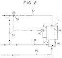
- FIG. 2 shows a first example of the controlling device 62, in which the temperature of the coolant in the gap 34 is controlled by adjusting the flow rate of the supplied coolant.
- the outlet line 61 of the pump is branched off into an auxiliary line 64, which is connected to the coolant supply line 63.
- a flow adjustment valve 65 for adjusting the flow rate of the coolant in the coolant supply line 63 is provided on a downstream side of the merge point with the auxiliary line 64.
- a thermometer 66 for measuring the temperature of the liquid is provided in the gap 34 of the motor portion 3.
- the controlling device 62 of the example compares the measured temperature of the liquid with a predetermined temperature, and transmits a signal to a valve driver (not shown) for driving the valve 65 so as to decrease the valve opening when the measured temperature is lower than the predetermined temperature, and to increase it when the temperature is higher than the predetermined temperature. Through such a process, the coolant flowing in the gap 34 is maintained at an appropriate high temperature.
- an appropriate high temperature means a temperature at which the motor portion 3 can operate and the kinematic viscosity coefficient of the coolant remains less than 1/3 of that at room temperature.
- TABLE 1 shows the variation of the kinematic viscosity coefficient of water and TABLE 2 shows the variation of the kinematic viscosity coefficient of an example of a heat transfer medium oil.
- the frictional loss at the gap 34 is negligible and the operational efficiency of the motor pump is fairly improved.
- the kinematic viscosity coefficient ⁇ at a temperature T generally is expressed as ⁇ T .
- water of 65°C is generally used as a coolant.
- the kinematic viscosity coefficient at this temperature ⁇ 65°C is 0.447, as shown in TABLE 1.
- the kinematic viscosity coefficient ⁇ 327°C is 0.118, which is less than 30% of ⁇ 65°C .
- the coolant is introduced from the passage 24 to the bearing portion 2, and flows into the gap 34 between the stator 32 and the rotor 33. There, the coolant temperature is raised by absorbing the heat generated in the stator 32 and the rotor 33. Then, the coolant flows through the internal passage 46 and merges with the fluid to be pumped at the inlet passage 41a. The fluid temperature changes in the process of heat exchange and frictional heating in the coolant passage including the gap 34.
- the flow rate of the coolant is controlled by the controlling device 62 so that the temperature of the liquid in the gap 34 between the stator 32 and the rotor 33 becomes high enough to keep the kinematic viscosity coefficient less than 1/3 of that at room temperature. As a result, the frictional resistance resulting from the liquid is small and the energy loss of the motor pump 1 can be lowered.
- the temperature of the liquid at the gap 34 is given as a summation of various temperature changes subjected to the liquid in the passage to the gap 34.
- another heat source may be required.
- the temperature of the liquid is a little lower, the temperature thereof may be raised to a predetermined temperature in the passage to the gap 34. If the pump is for pumping the high temperature liquid, it is not necessary to provide additional heat source to keep the coolant at the required temperature.
- the coolant can be mixed into the liquid to result in a simple structure of the flow passage.
- the coolant may be of a different kind of liquid than the pumped liquid.
- FIG. 3 shows another example of the controlling device 62, in which the temperature of the coolant in the gap 34 is controlled by adjusting the temperature of the coolant supplied to the passage 24.
- a heat exchanger 67 having a heat exchange medium line 69 is provided in the coolant supply line 63.
- An automatic valve 68 is provided in the heat exchange medium line 69 for controlling the temperature of the coolant by adjusting the flow rate of a heat exchange medium supplied to the heat exchanger 67 in response to the signal transmitted from the thermometer 66. That is, when the temperature of the coolant in the gap is higher than the target temperature, the automatic valve 68 increases the opening, and when the temperature of the coolant in the gap is lower than the target temperature, the automatic valve 68 decreases the opening.
- the coolant may be supplied from the outer source, however, a part of or all of the coolant may be supplied from the pump through the auxiliary line 64 when the pressure of the pump outlet line is sufficiently high.
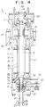
- FIGS. 4 and 5 show a motor pump 1 of a second embodiment of the present invention.
- the stator 32 and rotor 33 are cooled by a latent heat cooling process, which is more efficient than a sensible heat cooling process, by evaporating the coolant by the heat generated in the motor portion 3.
- a coolant outlet hole 70 is provided on the motor casing 30 in the region close to the pump casing 43. Between the motor casing 30 and a separation plate 71 of the pump casing 30 is provided a seal 72. By such configuration, the vapor evaporated inside the motor casing 30 flows uniformly in the entire annular gap 34 and is exhausted from the coolant outlet 70 without flowing into the pump casing 43.
- the coolant outlet 70 is connected to the coolant outlet line 73, in which a condenser 74 for condensing the vapor and a pressure reducing valve (not shown) positioned downstream the condenser 74 are provided.
- the condensed liquid is returned to the pump inlet line 60 after being adjusted of its pressure by the pressure reducing valve.
- the auxiliary line 64 branched off from the pump outlet line 61 is connected to the coolant supply line 63 in series so that the pumped liquid is used as coolant.
- a flow adjustment valve 75 for adjusting the flow rate of the liquid is provided at the merge point of the auxiliary line 64 and the pump outlet line 61.
- the coolant outlet line 73 has a thermometer 76 and a pressure gage 77 for respectively measuring the temperature and the pressure of the coolant flowing therein.
- the signals from the thermometer 76 and the pressure gage 78 are transmitted to a processor 78 for judging the state of the coolant, including whether the coolant is in a gaseous or liquidus state.
- the processor 78 generates a signal to the flow adjustment valve 75 for adjusting the flow rate of the liquid flowing into the motor portion 3 so that the coolant is evaporated by the heat generated in the motor portion 3.
- the coolant is prevented from flowing through from the coolant outlet 70 without being evaporated in the motor portion 3.
- the motor temperature is constant, it is possible to control the flow adjustment valve 75 only by the signal of the pressure gage 77.
- the high temperature liquid handled by the pump is used as a coolant, which flows through the annular gap 34 between the rotor 32 and the stator 33 to be evaporated.
- the coolant cools the motor effectively by a latent heat cooling process, which is more efficient than a sensible heat cooling process.
- the viscosity thereof is greatly reduced so that the friction loss due to the coolant is greatly decreased.
- the invention relates to a method for operating a motor pump comprising a pump portion; a motor portion including a rotor and a stator for driving said pump protion by way of a common rotation shaft; and a casing for housing said pump portion and said motor portion, said method comprising the step of providing a coolant to a gap between said stator and said rotor.
Landscapes
- Engineering & Computer Science (AREA)
- Power Engineering (AREA)
- Mechanical Engineering (AREA)
- General Engineering & Computer Science (AREA)
- Physics & Mathematics (AREA)
- Thermal Sciences (AREA)
- Structures Of Non-Positive Displacement Pumps (AREA)
- Motor Or Generator Cooling System (AREA)
- Control Of Non-Positive-Displacement Pumps (AREA)
Applications Claiming Priority (2)
| Application Number | Priority Date | Filing Date | Title |
|---|---|---|---|
| JP08873796A JP3346698B2 (ja) | 1996-03-18 | 1996-03-18 | 高温用モータポンプとその運転方法 |
| JP88737/96 | 1996-03-18 |
Publications (2)
| Publication Number | Publication Date |
|---|---|
| EP0802610A2 true EP0802610A2 (fr) | 1997-10-22 |
| EP0802610A3 EP0802610A3 (fr) | 1998-05-27 |
Family
ID=13951243
Family Applications (1)
| Application Number | Title | Priority Date | Filing Date |
|---|---|---|---|
| EP97104643A Withdrawn EP0802610A3 (fr) | 1996-03-18 | 1997-03-18 | Motopompe pour hautes températures et procédé pour son fonctionnement |
Country Status (3)
| Country | Link |
|---|---|
| US (1) | US5882182A (fr) |
| EP (1) | EP0802610A3 (fr) |
| JP (1) | JP3346698B2 (fr) |
Cited By (3)
| Publication number | Priority date | Publication date | Assignee | Title |
|---|---|---|---|---|
| DE102005038209A1 (de) * | 2005-08-12 | 2007-02-15 | Wilo Ag | Kühlmittelpumpe für Elektromotore |
| DE102009052856B3 (de) * | 2009-11-11 | 2010-09-09 | Leistritz Ag | Pumpe mit einer Magnetkupplung |
| EP1826887A3 (fr) * | 2006-02-24 | 2012-11-21 | General Electric Company | Pompe avec moteur électrique qui peut être utilisée dans des pipelines et procédé correspondant |
Families Citing this family (28)
| Publication number | Priority date | Publication date | Assignee | Title |
|---|---|---|---|---|
| US7053139B2 (en) * | 1998-12-30 | 2006-05-30 | Qi Wang | Inhibiting polymer oxidation using non-phenolic antioxidants |
| US6722854B2 (en) | 2001-01-24 | 2004-04-20 | Sundyne Corporation | Canned pump with ultrasonic bubble detector |
| US6626649B2 (en) * | 2001-07-18 | 2003-09-30 | Advanced Thermal Sciences Corp. | Pump system employing liquid filled rotor |
| US20040040660A1 (en) * | 2001-10-03 | 2004-03-04 | Biberger Maximilian Albert | High pressure processing chamber for multiple semiconductor substrates |
| US20050227187A1 (en) * | 2002-03-04 | 2005-10-13 | Supercritical Systems Inc. | Ionic fluid in supercritical fluid for semiconductor processing |
| US7225820B2 (en) * | 2003-02-10 | 2007-06-05 | Tokyo Electron Limited | High-pressure processing chamber for a semiconductor wafer |
| US7270137B2 (en) * | 2003-04-28 | 2007-09-18 | Tokyo Electron Limited | Apparatus and method of securing a workpiece during high-pressure processing |
| US20040231707A1 (en) * | 2003-05-20 | 2004-11-25 | Paul Schilling | Decontamination of supercritical wafer processing equipment |
| US20050022850A1 (en) * | 2003-07-29 | 2005-02-03 | Supercritical Systems, Inc. | Regulation of flow of processing chemistry only into a processing chamber |
| US7186093B2 (en) * | 2004-10-05 | 2007-03-06 | Tokyo Electron Limited | Method and apparatus for cooling motor bearings of a high pressure pump |
| US20060102282A1 (en) * | 2004-11-15 | 2006-05-18 | Supercritical Systems, Inc. | Method and apparatus for selectively filtering residue from a processing chamber |
| US20060185694A1 (en) * | 2005-02-23 | 2006-08-24 | Richard Brown | Rinsing step in supercritical processing |
| US7550075B2 (en) * | 2005-03-23 | 2009-06-23 | Tokyo Electron Ltd. | Removal of contaminants from a fluid |
| US7380984B2 (en) * | 2005-03-28 | 2008-06-03 | Tokyo Electron Limited | Process flow thermocouple |
| US7767145B2 (en) * | 2005-03-28 | 2010-08-03 | Toyko Electron Limited | High pressure fourier transform infrared cell |
| US20060225772A1 (en) * | 2005-03-29 | 2006-10-12 | Jones William D | Controlled pressure differential in a high-pressure processing chamber |
| US7494107B2 (en) * | 2005-03-30 | 2009-02-24 | Supercritical Systems, Inc. | Gate valve for plus-atmospheric pressure semiconductor process vessels |
| US20060219268A1 (en) * | 2005-03-30 | 2006-10-05 | Gunilla Jacobson | Neutralization of systemic poisoning in wafer processing |
| DE102007036239A1 (de) * | 2007-08-02 | 2009-02-05 | Continental Automotive Gmbh | Verfahren zur Abfuhr von Wärme von Bauteilen einer Flüssigkeitspumpe |
| JP5271928B2 (ja) * | 2010-01-26 | 2013-08-21 | 株式会社酉島製作所 | 循環ポンプ |
| JP5189185B2 (ja) * | 2011-06-20 | 2013-04-24 | 株式会社小松製作所 | 電動機 |
| CN102562582B (zh) * | 2012-03-05 | 2015-02-25 | 安徽凯特泵业有限公司 | 一种硅钢涂层液输送泵 |
| US9425664B2 (en) | 2012-05-09 | 2016-08-23 | Thingap, Llc | Composite stator for electromechanical power conversion |
| CN103206372A (zh) * | 2013-03-18 | 2013-07-17 | 丹阳市华昱机电设备有限公司 | 新型水泵 |
| US12385481B2 (en) * | 2016-05-27 | 2025-08-12 | Ghsp, Inc. | Thermistor flow path |
| US11959481B2 (en) * | 2016-05-27 | 2024-04-16 | Ghsp, Inc. | Thermistor flow path |
| US10914305B2 (en) * | 2016-05-27 | 2021-02-09 | Ghsp, Inc. | Thermistor flow path |
| JP6805065B2 (ja) * | 2017-04-21 | 2020-12-23 | 株式会社日立産機システム | 水中ポンプおよびそれを用いた水中ポンプシステム |
Family Cites Families (11)
| Publication number | Priority date | Publication date | Assignee | Title |
|---|---|---|---|---|
| DE3120232C2 (de) * | 1981-05-21 | 1985-03-21 | Klein, Schanzlin & Becker Ag, 6710 Frankenthal | Druckausgleichseinrichtung für den Elektromotor eines gekapselten Kreiselpumpen-Motor-Aggregates |
| SU1060807A1 (ru) * | 1982-05-12 | 1983-12-15 | Криворожский Ордена Трудового Красного Знамени Горнорудный Институт | Устройство дл регулировани расхода охлаждающей среды компрессора |
| JPS5958197A (ja) * | 1982-09-28 | 1984-04-03 | Nikkiso Co Ltd | キヤンドモ−タポンプ |
| JPS59226225A (ja) * | 1983-06-08 | 1984-12-19 | Nissan Motor Co Ltd | 自動車用内燃機関の冷却水温制御装置 |
| JPS618492A (ja) * | 1984-06-25 | 1986-01-16 | Mitsubishi Electric Corp | 回転式圧縮機 |
| JPH01174231A (ja) * | 1987-12-25 | 1989-07-10 | Mitsubishi Heavy Ind Ltd | キャンドモータないしは浸水型モータ駆動の高温高圧流体ポンプ |
| SU1687857A1 (ru) * | 1988-11-30 | 1991-10-30 | Е.А. Похиленко | Компрессорна установка |
| DE4009198A1 (de) * | 1990-03-22 | 1991-09-26 | Rheinhuette Gmbh & Co | Trockenlaufsicherung fuer spaltrohrmotorpumpen |
| US5129795A (en) * | 1991-05-31 | 1992-07-14 | Powerdyne Corporation | Motor driven pump |
| US5221191A (en) * | 1992-04-29 | 1993-06-22 | Carrier Corporation | Horizontal rotary compressor |
| JP2501074B2 (ja) * | 1993-03-01 | 1996-05-29 | 日機装株式会社 | キャンドモ―タポンプ |
-
1996
- 1996-03-18 JP JP08873796A patent/JP3346698B2/ja not_active Expired - Fee Related
-
1997
- 1997-03-18 EP EP97104643A patent/EP0802610A3/fr not_active Withdrawn
- 1997-03-18 US US08/819,939 patent/US5882182A/en not_active Expired - Fee Related
Cited By (3)
| Publication number | Priority date | Publication date | Assignee | Title |
|---|---|---|---|---|
| DE102005038209A1 (de) * | 2005-08-12 | 2007-02-15 | Wilo Ag | Kühlmittelpumpe für Elektromotore |
| EP1826887A3 (fr) * | 2006-02-24 | 2012-11-21 | General Electric Company | Pompe avec moteur électrique qui peut être utilisée dans des pipelines et procédé correspondant |
| DE102009052856B3 (de) * | 2009-11-11 | 2010-09-09 | Leistritz Ag | Pumpe mit einer Magnetkupplung |
Also Published As
| Publication number | Publication date |
|---|---|
| JPH09250487A (ja) | 1997-09-22 |
| JP3346698B2 (ja) | 2002-11-18 |
| US5882182A (en) | 1999-03-16 |
| EP0802610A3 (fr) | 1998-05-27 |
Similar Documents
| Publication | Publication Date | Title |
|---|---|---|
| US5882182A (en) | High-temperature motor pump and method for operating thereof | |
| TWI638123B (zh) | 馬達外殼溫度控制系統 | |
| CN104254744B (zh) | 离心式制冷剂蒸气压缩机 | |
| US8950206B2 (en) | Compressor assembly having electronics cooling system and method | |
| KR890004397B1 (ko) | 냉각장치의 전기모우터식 압축기를 보호하는 제어장치와 그 방법 | |
| EP0644333A2 (fr) | Système de commande d'une pompe | |
| US6349552B2 (en) | Temperature control device for thermal medium fluid | |
| KR900005977B1 (ko) | 냉동시스템의 작동방법 및 냉동시스템의 제어시스템 | |
| KR950003791B1 (ko) | 자동 냉각기 설비의 평형 | |
| EP0509844B1 (fr) | Appareillage pour le refroidissement d'un dispositif électronique | |
| KR930000404B1 (ko) | 냉매가열식 냉난방기 | |
| EP0226215B1 (fr) | Appareil d'usinage par étincelles | |
| US5355846A (en) | Cooling device for use in engine | |
| US4262488A (en) | System and method for controlling the discharge temperature of a high pressure stage of a multi-stage centrifugal compression refrigeration unit | |
| US4248292A (en) | Heat transfer control circuit for a heat pump | |
| CN219108056U (zh) | 空调变频器的冷却系统、空调设备 | |
| JP2682629B2 (ja) | Lsiの冷却装置 | |
| US2487852A (en) | Refrigerant condenser for mechanical refrigerating machines | |
| CN115666089A (zh) | 电子设备及其内部环境温度调节控制方法 | |
| US3238998A (en) | Heat exchange devices | |
| JPH0575284A (ja) | 冷却装置 | |
| JPS6210530A (ja) | 温室空調用ヒ−トポンプ | |
| CN121617788B (zh) | 一种用于干式变压器的泵驱式相变冷却系统的控制方法 | |
| US3064148A (en) | Auxiliary motor housing | |
| JPH0460217A (ja) | 油潤滑軸受 |
Legal Events
| Date | Code | Title | Description |
|---|---|---|---|
| PUAI | Public reference made under article 153(3) epc to a published international application that has entered the european phase |
Free format text: ORIGINAL CODE: 0009012 |
|
| AK | Designated contracting states |
Kind code of ref document: A2 Designated state(s): CH DE GB LI NL |
|
| PUAL | Search report despatched |
Free format text: ORIGINAL CODE: 0009013 |
|
| AK | Designated contracting states |
Kind code of ref document: A3 Designated state(s): CH DE GB LI NL |
|
| 17P | Request for examination filed |
Effective date: 19981123 |
|
| 17Q | First examination report despatched |
Effective date: 20001017 |
|
| GRAH | Despatch of communication of intention to grant a patent |
Free format text: ORIGINAL CODE: EPIDOS IGRA |
|
| STAA | Information on the status of an ep patent application or granted ep patent |
Free format text: STATUS: THE APPLICATION IS DEEMED TO BE WITHDRAWN |
|
| 18D | Application deemed to be withdrawn |
Effective date: 20031015 |