EP0802680A2 - Procédé de segmentation d'images - Google Patents
Procédé de segmentation d'images Download PDFInfo
- Publication number
- EP0802680A2 EP0802680A2 EP97201016A EP97201016A EP0802680A2 EP 0802680 A2 EP0802680 A2 EP 0802680A2 EP 97201016 A EP97201016 A EP 97201016A EP 97201016 A EP97201016 A EP 97201016A EP 0802680 A2 EP0802680 A2 EP 0802680A2
- Authority
- EP
- European Patent Office
- Prior art keywords
- regions
- region
- image
- pixels
- intermediate regions
- Prior art date
- Legal status (The legal status is an assumption and is not a legal conclusion. Google has not performed a legal analysis and makes no representation as to the accuracy of the status listed.)
- Granted
Links
Images

Classifications
-
- H—ELECTRICITY
- H04—ELECTRIC COMMUNICATION TECHNIQUE
- H04N—PICTORIAL COMMUNICATION, e.g. TELEVISION
- H04N19/00—Methods or arrangements for coding, decoding, compressing or decompressing digital video signals
- H04N19/50—Methods or arrangements for coding, decoding, compressing or decompressing digital video signals using predictive coding
- H04N19/503—Methods or arrangements for coding, decoding, compressing or decompressing digital video signals using predictive coding involving temporal prediction
- H04N19/51—Motion estimation or motion compensation
- H04N19/537—Motion estimation other than block-based
-
- H—ELECTRICITY
- H04—ELECTRIC COMMUNICATION TECHNIQUE
- H04N—PICTORIAL COMMUNICATION, e.g. TELEVISION
- H04N19/00—Methods or arrangements for coding, decoding, compressing or decompressing digital video signals
- H04N19/50—Methods or arrangements for coding, decoding, compressing or decompressing digital video signals using predictive coding
- H04N19/503—Methods or arrangements for coding, decoding, compressing or decompressing digital video signals using predictive coding involving temporal prediction
- H04N19/51—Motion estimation or motion compensation
-
- H—ELECTRICITY
- H04—ELECTRIC COMMUNICATION TECHNIQUE
- H04N—PICTORIAL COMMUNICATION, e.g. TELEVISION
- H04N19/00—Methods or arrangements for coding, decoding, compressing or decompressing digital video signals
- H04N19/20—Methods or arrangements for coding, decoding, compressing or decompressing digital video signals using video object coding
Definitions
- the invention relates to a method for segmenting images of an image signal, the image being broken down into regions within an image in which adjacent pixels are combined.
- object-oriented encoding attempts to classify the image on the basis of the image content, ie the objects reproduced in this image. This has the advantage that transition effects occurring between the blocks do not appear to be a nuisance, since they coincide with the object boundaries.
- This object is achieved in that the color type values of the pixels are used for the region formation, that those neighboring Pixels of an image can be combined into a coherent region, which have similar chromaticity values, and that a common chromaticity value is provided for the pixels of a region.
- the invention is based on the knowledge that, for the object-oriented coding and thus for the segmentation of the image preceding it, an even higher data reduction than in the known methods can be achieved in particular by focusing on the color type values of the pixels for the region formation. This is possible because the human eye is much less sensitive to color stimuli than to brightness information. It is therefore possible to go as far as to provide only one color type value per region for all the pixels belonging to the region. For this purpose, those contiguous neighboring pixels are drawn together to form a region that have similar color values within predefined limits. This means that only one color value is used for all pixels in a region, which is possible due to the relationships mentioned above.
- the color type value assigned to a region can advantageously, as is provided according to an embodiment of the invention, correspond to the mean value of the original color type values of the pixels added to the region. This results in an on average minimal deviation of the color type value of the region from the original color type values of the pixels belonging to it.
- the brightness values of the pixels can also be used for the formation of the regions, however, as is provided in accordance with a further embodiment of the invention, they should then be weighted less than their color type values in order to obtain the advantages mentioned above.
- the formation of the regions with a common chromaticity value of all the pixels of a region is carried out in two stages in such a way that intermediate regions are formed in a first stage, the generation of both the chromaticity and the regions the brightness values of the pixels are used, and in a second stage the regions are formed from the intermediate regions in such a way that the intermediate regions are combined into regions, intermediate regions with similar chromaticity values forming a common region with a common chromaticity Value can be summarized.
- the result is that the region is formed on the basis of the color type values of the pixels.
- a region is formed in a manner known per se, the generation of both the color type and the brightness values of the pixels being used. This creates a segmentation that is based on both values.
- These intermediate regions are summarized exclusively with regard to their color type values to the effect that intermediate regions that have similar color type values within a predeterminable limit have to be combined into a common region. This common region then has a color type value for all pixels of this region.
- This two-stage procedure has the advantage that in the first stage the region formation can detect the object boundaries even more reliably, since the brightness values are also used there.
- the intermediate regions formed in this way are then summarized again for the formation of the regions, so that the desired effect of reducing the number of regions and thus the amount of data is ultimately achieved.
- the regions are formed in two stages
- a motion estimation of the intermediate regions in an image I n and the subsequent image I n + 1 the new position of the intermediate region in the image I n + 1 is determined on the basis of the motion vectors determined for each intermediate region by means of the movement estimate, so that the pixels of the image I n + 1 belonging to each shifted intermediate region are subsequently adapted will be that pixels of the image I n + 1 not captured by these adapted intermediate regions are added to one of these intermediate regions or newly formed intermediate regions and that in the second stage the intermediate regions are then combined into regions.
- the intermediate regions initially formed in the first stage do not generally have to be regenerated in every image. Since the image contents of successive images are generally very similar (apart from camera changes, scene changes or the like), it is possible to find a region in a subsequent image based on the motion estimation, even if it should have changed its position in the image. By locating the region again using the motion estimation, it does not have to be formed anew, instead their data can be taken from the previous picture. This results in a reduction in the coding effort of the computing effort and thus the computing time.
- the intermediate regions tracked in this way in successive images are each combined into regions in the manner described above, intermediate regions with similar chromaticity values being merged into a common region with only one chromaticity value.
- a further embodiment of the invention provides that for successive images in an image I n + 1, the intermediate regions combined in the previous image In to an assigned region are searched again, whereby Intermediate regions moved between the images I n and I n + 1 can be found with the help of the movement information that an attempt is being made to merge these intermediate regions into the same assigned region and for those intermediate regions for which this is not successful, to merge with other or new ones Regions.
- intermediate regions fused into one region are generally also found in a subsequent image.
- the intermediate regions are merged into the regions, there is therefore the possibility of fusing the same intermediate regions again, if appropriate in the image, into the common region in successive images.
- This also has the advantage for this processing step that the intermediate regions can be found again and that they can be merged into the region in the same way as in the previous image. This means that no recalculation is required here either. Those regions for which this is not possible, for example because intermediate regions are not present in the image content or new intermediate regions appear, are merged with other regions or an or several new regions were formed, in which the remaining intermediate regions can then be merged.
- the coding of the shape of the regions is carried out by means of a chain code in which the position of an initial pixel of the edge of a region is completely coded and in which the positions of the other pixels of the edge of the region are successive starting from the starting pixel are coded in such a way that in each case only the coding is carried out as to whether the pixel in question is arranged to the left of, to the right of, above or below the previously coded pixel.
- coding of the shape of the segments is also necessary.
- a data-saving way of coding the shape of the regions is possible using a chain code.
- the complete position specification of this pixel is coded only from one output pixel.
- This starting pixel lies on the edge of a region.
- only a relative coding of the neighbors is then carried out for each further pixel of the edge of the region that is adjacent to this.
- the pixel adjacent to the starting pixel is only coded as to whether it is above, below, to the left of or to the right of the starting pixel.
- This process is then repeated for every further adjacent pixel of the edge until the entire pixels of the edge of the region are encoded in this way.
- 2-bit coding is sufficient for every further pixel on the edge of a region.
- Fig. 1 shows a schematic representation of the procedure for the two-stage coding.
- a signal I which contains the image content of an image, possibly of several successive images, first reaches stage 1, in which a first division of the image content into intermediate segments is carried out. This can be done, for example, in a manner known per se by taking into account the brightness and color values of the pixels of the image content.
- the block supplies the output signal with a label image in which all points of an intermediate region i are identified by the number i.
- This data of the intermediate regions is processed in a further circuit block 2 in such a way that it is checked which color type values the pixels of the regions have. Among the intermediate regions there are probably those that have similar chromaticity values for their pixels. These intermediate regions are then merged into regions. For each of these regions, only one color type value is provided for all pixels in this region.
- the circuit block 2 of the representation according to FIG. 1 supplies this data S of the regions on the output side.
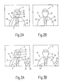
- FIG. 2A shows an image with registered intermediate regions, as can be obtained in the first stage of the method.
- Figure 2B shows the final regions formed from the chrominance values.
- intermediate regions have been formed for the illustrated chest image of a person.
- Six intermediate regions have been formed solely for the head 11 of the person shown, in particular in addition to the facial skin 10 also a separate intermediate region 12 for the nose and an intermediate region 13 for the mouth of the person shown.
- a total of seven intermediate regions have been formed in the chest region 14, in particular a region 15 for the arm of the person or the sleeve and a region 16 for the right half of the chest.
- a further intermediate region 17 which for example represents a button on the jacket 16.
- These intermediate regions have been formed on the basis of both the brightness and the color values of the image content.
- the invention merges into regions as are shown in FIG. 2B.
- the formation of these regions entered in FIG. 2B can also be generated immediately from the original image content instead of the representation in FIG. 2, which is carried out in two stages.
- the illustration according to FIG. 2B shows, among other things, that two regions could be saved for the head region compared to the intermediate regions.
- the intermediate regions 12 of the nose and 13 of the mouth of the intermediate region 10, which reproduces the remaining facial content, have been struck.
- these three intermediate regions 10, 12 and 13 have become a region 21, with all pixels of region 21 having a common color type value exhibit.
- This color type value can have arisen, for example, by averaging the color type values of regions 10, 12 and 13.
- regions 15, 16 and 17 have merged into a new region 22 in the chest area. Similar to the face area, this is possible because the intermediate regions 15, 16 and 17 were those that have similar color values.
- there are different parts of the jacket that differ more by brightness values than by color values.
- FIG. 2B shows the regions formed which reproduce those image contents which have similar chromaticity values.
- This region formation is helpful for an encoding of the data of the image, since the region formation on the one hand shows the boundaries of different objects shown in the image and, on the other hand, a considerable data reduction of the color values is already achieved through the region formation.
- the subsequent coding only the brightness values of the pixels have to be coded in a suitable manner.
- two-stage coding was carried out within an image without taking into account the image contents of previous or subsequent images.
- FIG. 3A A representation corresponding to FIG. 2A is indicated in FIG. 3A.
- the picture content shown in FIG. 3A is the picture following the picture in FIG. 2A.
- the intermediate regions formed in FIG. 2A are tracked using a motion estimation. By means of this motion estimation, most of the intermediate regions can be found again in the example shown. In the example of FIGS. 2A and 3A, the person shown has moved little. Based on the motion estimation, the intermediate regions would still be able to be tracked even if, for example, the person had moved from the left half of the image to the right half of the image.
- intermediate region 17 of FIG. 2A could be found again.
- the intermediate region 17 according to FIG. 2A could not be found again, since a sheet has been pushed in front of the breast of the person depicted, which has been combined into a new intermediate region 31 for the segmentation of the image shown in FIG. 3A.
- an arm is also shown, the sleeves of which are combined into an intermediate region 32 and the hand of which is combined into an intermediate region 33.
- the hand 33 has a different color than the areas surrounding it, so that the intermediate region 33 must become a new region 43.
- FIG. 3 shows that both in the first stage and in the second stage, the image contents of the model and of the intermediate regions or regions formed in these for the segmentation of the following image according to FIG. 3A. This means that a large number of regions and intermediate regions no longer need to be recalculated because the associated data can be taken from the model.
- FIG. 4 shows in a schematic block diagram how such a two-stage segmentation, in which the image contents of previous images are taken into account, can be carried out.
- a circuit block 51 is successively supplied with the data of successive images I n , I n + 1 , etc.
- the formation of the intermediate regions takes place corresponding to the circuit block 1 according to FIG. 1.
- the output data generated in this case are in turn fed to the circuit block 51 via a delay element 52, so that, for example, the intermediate regions determined in the model I n are available for an image I n + 1 and their data can be used for the motion estimation.
- Circuit block 51 is followed by a circuit block 53, in which regions are formed in accordance with circuit block 2 as shown in FIG. 1.
- the representation according to FIG. 4 takes into account the intermediate regions and the regions of the model.
- circuit block 53 also supplies data which indicate the intermediate regions from which a region is composed.
- the data for the regions of an image supplied by the circuit block 53 are delayed by means of a delay element, so that, for example, the regions formed in the previous image In are available for the formation of the regions of an image I n + 1 .
- circuit block 55 which encodes the shape and arrangement of the regions and outputs them as region data S.
- region data S indicates their location, size, etc.
- chain code which indicates the position of all boundary points of a region. Starting from an initial pixel whose position is transmitted completely coded, only the relative position of neighboring pixels is transmitted above, below, to the left of or to the right of the respective neighboring pixel.
- FIG. 4 also shows a circuit block 56 in which the color data are encoded. Since the segmentation and, in particular, the formation of the regions was previously carried out in such a way that all the pixels belonging to a region now only have a common color type value, coding is only required region by region.
- the circuit block 56 therefore generates, for example, a color difference pair UV C for each region, which specifies the coded color information for all pixels of a region.
- a circuit block 57 is also provided, which outputs the brightness values of the pixels in coded form as signal Y c . If necessary, the data of the intermediate regions as well as of the regions can be used for the coding of the brightness information. For the brightness information, a more detailed coding of the individual values of the pixels may have to be carried out, so that not all pixels of a region can be coded with the same brightness value.
- FIG. 4 shows the image segmentation according to the invention on the basis of the schematic illustration of the circuit blocks 51 to 54.
- the coding of the image content, which is carried out in the circuit block 57, is not the subject of the invention.
Landscapes
- Engineering & Computer Science (AREA)
- Multimedia (AREA)
- Signal Processing (AREA)
- Compression Or Coding Systems Of Tv Signals (AREA)
- Image Analysis (AREA)
- Image Processing (AREA)
- Compression Of Band Width Or Redundancy In Fax (AREA)
Applications Claiming Priority (2)
| Application Number | Priority Date | Filing Date | Title |
|---|---|---|---|
| DE19615493A DE19615493A1 (de) | 1996-04-19 | 1996-04-19 | Verfahren zur Bildsegmentierung |
| DE19615493 | 1996-04-19 |
Publications (3)
| Publication Number | Publication Date |
|---|---|
| EP0802680A2 true EP0802680A2 (fr) | 1997-10-22 |
| EP0802680A3 EP0802680A3 (fr) | 2000-07-19 |
| EP0802680B1 EP0802680B1 (fr) | 2007-02-14 |
Family
ID=7791746
Family Applications (1)
| Application Number | Title | Priority Date | Filing Date |
|---|---|---|---|
| EP97201016A Expired - Lifetime EP0802680B1 (fr) | 1996-04-19 | 1997-04-07 | Procédé de segmentation d'images |
Country Status (4)
| Country | Link |
|---|---|
| EP (1) | EP0802680B1 (fr) |
| JP (1) | JP4123539B2 (fr) |
| CN (1) | CN1106765C (fr) |
| DE (2) | DE19615493A1 (fr) |
Cited By (9)
| Publication number | Priority date | Publication date | Assignee | Title |
|---|---|---|---|---|
| EP1388815A3 (fr) * | 2002-04-25 | 2005-11-16 | Microsoft Corporation | Système de segmentation d'images en couches |
| US7024039B2 (en) | 2002-04-25 | 2006-04-04 | Microsoft Corporation | Block retouching |
| US7043079B2 (en) | 2002-04-25 | 2006-05-09 | Microsoft Corporation | “Don't care” pixel interpolation |
| US7110596B2 (en) | 2002-04-25 | 2006-09-19 | Microsoft Corporation | System and method facilitating document image compression utilizing a mask |
| US7120297B2 (en) | 2002-04-25 | 2006-10-10 | Microsoft Corporation | Segmented layered image system |
| US7164797B2 (en) | 2002-04-25 | 2007-01-16 | Microsoft Corporation | Clustering |
| US7263227B2 (en) | 2002-04-25 | 2007-08-28 | Microsoft Corporation | Activity detector |
| US7392472B2 (en) | 2002-04-25 | 2008-06-24 | Microsoft Corporation | Layout analysis |
| CN109816659A (zh) * | 2019-01-28 | 2019-05-28 | 北京旷视科技有限公司 | 图像分割方法、装置及系统 |
Families Citing this family (7)
| Publication number | Priority date | Publication date | Assignee | Title |
|---|---|---|---|---|
| US7526115B2 (en) * | 2004-02-23 | 2009-04-28 | Siemens Medical Solutions Usa, Inc. | System and method for toboggan based object segmentation using divergent gradient field response in images |
| JP4539964B2 (ja) * | 2004-07-21 | 2010-09-08 | 大日本スクリーン製造株式会社 | 画像の領域分割 |
| KR101626688B1 (ko) | 2010-04-13 | 2016-06-01 | 지이 비디오 컴프레션, 엘엘씨 | 샘플 영역 병합 |
| TWI575887B (zh) | 2010-04-13 | 2017-03-21 | Ge影像壓縮有限公司 | 在樣本陣列多元樹細分中之繼承技術 |
| RS63059B1 (sr) | 2010-04-13 | 2022-04-29 | Ge Video Compression Llc | Kodiranje videa primenom podele sa više stabala na slikama |
| BR122020007923B1 (pt) | 2010-04-13 | 2021-08-03 | Ge Video Compression, Llc | Predição interplano |
| CN102957904A (zh) * | 2011-08-24 | 2013-03-06 | 上海山景集成电路技术有限公司 | 对图像信息进行压缩编码的方法、系统及设备 |
Family Cites Families (1)
| Publication number | Priority date | Publication date | Assignee | Title |
|---|---|---|---|---|
| KR0181052B1 (ko) * | 1995-03-31 | 1999-05-01 | 배순훈 | 고화질 영상 시스템의 영역 분할 장치 |
-
1996
- 1996-04-19 DE DE19615493A patent/DE19615493A1/de not_active Withdrawn
-
1997
- 1997-04-07 DE DE59712814T patent/DE59712814D1/de not_active Expired - Lifetime
- 1997-04-07 EP EP97201016A patent/EP0802680B1/fr not_active Expired - Lifetime
- 1997-04-18 CN CN97110768A patent/CN1106765C/zh not_active Expired - Lifetime
- 1997-04-21 JP JP10327297A patent/JP4123539B2/ja not_active Expired - Fee Related
Cited By (15)
| Publication number | Priority date | Publication date | Assignee | Title |
|---|---|---|---|---|
| EP1388815A3 (fr) * | 2002-04-25 | 2005-11-16 | Microsoft Corporation | Système de segmentation d'images en couches |
| US7024039B2 (en) | 2002-04-25 | 2006-04-04 | Microsoft Corporation | Block retouching |
| US7043079B2 (en) | 2002-04-25 | 2006-05-09 | Microsoft Corporation | “Don't care” pixel interpolation |
| US7110596B2 (en) | 2002-04-25 | 2006-09-19 | Microsoft Corporation | System and method facilitating document image compression utilizing a mask |
| US7120297B2 (en) | 2002-04-25 | 2006-10-10 | Microsoft Corporation | Segmented layered image system |
| US7164797B2 (en) | 2002-04-25 | 2007-01-16 | Microsoft Corporation | Clustering |
| US7263227B2 (en) | 2002-04-25 | 2007-08-28 | Microsoft Corporation | Activity detector |
| US7376275B2 (en) | 2002-04-25 | 2008-05-20 | Microsoft Corporation | Clustering |
| US7376266B2 (en) | 2002-04-25 | 2008-05-20 | Microsoft Corporation | Segmented layered image system |
| US7386171B2 (en) | 2002-04-25 | 2008-06-10 | Microsoft Corporation | Activity detector |
| US7392472B2 (en) | 2002-04-25 | 2008-06-24 | Microsoft Corporation | Layout analysis |
| US7397952B2 (en) | 2002-04-25 | 2008-07-08 | Microsoft Corporation | “Don't care” pixel interpolation |
| US7512274B2 (en) | 2002-04-25 | 2009-03-31 | Microsoft Corporation | Block retouching |
| US7764834B2 (en) | 2002-04-25 | 2010-07-27 | Microsoft Corporation | System and method facilitating document image compression utilizing a mask |
| CN109816659A (zh) * | 2019-01-28 | 2019-05-28 | 北京旷视科技有限公司 | 图像分割方法、装置及系统 |
Also Published As
| Publication number | Publication date |
|---|---|
| CN1106765C (zh) | 2003-04-23 |
| JP4123539B2 (ja) | 2008-07-23 |
| DE19615493A1 (de) | 1997-10-23 |
| JPH1069544A (ja) | 1998-03-10 |
| CN1168056A (zh) | 1997-12-17 |
| EP0802680A3 (fr) | 2000-07-19 |
| DE59712814D1 (de) | 2007-03-29 |
| EP0802680B1 (fr) | 2007-02-14 |
Similar Documents
| Publication | Publication Date | Title |
|---|---|---|
| EP0802680B1 (fr) | Procédé de segmentation d'images | |
| DE69428239T2 (de) | Verfahren und Vorrichtung zum Extrahieren bestimmter Gebiete | |
| DE69225941T2 (de) | Bildkodierung und/oder -dekodierung | |
| DE69718830T2 (de) | Verfahren zur verallgemeinerten darstellung und kodierung inhaltsabhängig skalierbarer formen | |
| DE4242796C2 (de) | Hocheffizientes Kodierverfahren für mit Zweipegelbildern vermischte natürliche Bilder | |
| DE69313703T2 (de) | Unter-Ensemble zur Bildkodierung mit Korrektur der Aktualisierung der kodierenden Daten und Unter-Ensemble zur Dekodierung der diese Bilder darstellenden Signale | |
| DE69628282T2 (de) | Verfahren zur kompression mehrerer videobilder | |
| DE60003032T2 (de) | Verfahren zur bildsegmentation | |
| DE112016005905B4 (de) | Verfahren und System zum Verschmelzen erfasster Messungen | |
| DE69515647T2 (de) | Schnittstelle für videokamera und intra / inter-frame kodierer | |
| DE69226112T2 (de) | Bildkantendetektionssystem | |
| DE19743202B4 (de) | Verfahren zum Codieren eines Bewegungsvektors | |
| DE69711215T2 (de) | Verfahren zur verarbeitung eines videostroms | |
| DE69904610T2 (de) | Bewegungsschätzungsverfahren zur Reduzierung der Übertragungskosten von Bewegungsvektoren | |
| DE3905234C2 (fr) | ||
| DE69229146T2 (de) | Verfahren und Vorrichtung zur Detektion eines Bewegungsvektors sowie Kodierungsverfahren und Vorrichtung zur Anwendung eines solchen Verfahrens und Vorrichtung | |
| DE69512824T2 (de) | Kompressions- und Dekompressionsverfahren für mehrdimensionale mehrwertige Farbbilder | |
| EP0941613B1 (fr) | Procede de codage d'une image numerisee | |
| EP0897247A2 (fr) | Procédé de calcul de vecteurs de mouvement | |
| DE10084783B3 (de) | System und Verfahren zur Generierung von Videoframes | |
| DE10250781B4 (de) | Verfahren und Vorrichtung zur automatischen Segmentierung eines Vordergrundobjektes in einem Bild | |
| DE69124823T2 (de) | Verarbeitung von Bildsignalen | |
| DE60320076T2 (de) | Verfahren zur elektronischen farbentfernung unter nutzung räumlicher beziehungen zur verbesserung der genauigkeit | |
| DE19756224A1 (de) | Verfahren zur Bestimmung der Bewegung eines sich bewegenden Bildes unter Verwendung eines zweidimensionalen Dreieckmustergittermodells | |
| EP0802679A2 (fr) | Procédé de segmentation d'images |
Legal Events
| Date | Code | Title | Description |
|---|---|---|---|
| PUAI | Public reference made under article 153(3) epc to a published international application that has entered the european phase |
Free format text: ORIGINAL CODE: 0009012 |
|
| AK | Designated contracting states |
Kind code of ref document: A2 Designated state(s): DE FI FR GB |
|
| RAP3 | Party data changed (applicant data changed or rights of an application transferred) |
Owner name: KONINKLIJKE PHILIPS ELECTRONICS N.V. Owner name: PHILIPS CORPORATE INTELLECTUAL PROPERTY GMBH |
|
| PUAL | Search report despatched |
Free format text: ORIGINAL CODE: 0009013 |
|
| AK | Designated contracting states |
Kind code of ref document: A3 Designated state(s): DE FI FR GB |
|
| RIN1 | Information on inventor provided before grant (corrected) |
Inventor name: GRIGAT, ROLF-RAINER, PROF.-DR.-ING. Inventor name: SIGGELKOW, SVEN Inventor name: IBENTHAL, ACHIM |
|
| 17P | Request for examination filed |
Effective date: 20010119 |
|
| RAP1 | Party data changed (applicant data changed or rights of an application transferred) |
Owner name: KONINKLIJKE PHILIPS ELECTRONICS N.V. Owner name: PHILIPS CORPORATE INTELLECTUAL PROPERTY GMBH |
|
| RAP1 | Party data changed (applicant data changed or rights of an application transferred) |
Owner name: KONINKLIJKE PHILIPS ELECTRONICS N.V. Owner name: PHILIPS INTELLECTUAL PROPERTY & STANDARDS GMBH |
|
| 17Q | First examination report despatched |
Effective date: 20050705 |
|
| GRAP | Despatch of communication of intention to grant a patent |
Free format text: ORIGINAL CODE: EPIDOSNIGR1 |
|
| GRAS | Grant fee paid |
Free format text: ORIGINAL CODE: EPIDOSNIGR3 |
|
| GRAA | (expected) grant |
Free format text: ORIGINAL CODE: 0009210 |
|
| AK | Designated contracting states |
Kind code of ref document: B1 Designated state(s): DE FI FR GB |
|
| PG25 | Lapsed in a contracting state [announced via postgrant information from national office to epo] |
Ref country code: FI Free format text: LAPSE BECAUSE OF FAILURE TO SUBMIT A TRANSLATION OF THE DESCRIPTION OR TO PAY THE FEE WITHIN THE PRESCRIBED TIME-LIMIT Effective date: 20070214 |
|
| REG | Reference to a national code |
Ref country code: GB Ref legal event code: FG4D Free format text: NOT ENGLISH |
|
| REF | Corresponds to: |
Ref document number: 59712814 Country of ref document: DE Date of ref document: 20070329 Kind code of ref document: P |
|
| GBT | Gb: translation of ep patent filed (gb section 77(6)(a)/1977) |
Effective date: 20070516 |
|
| ET | Fr: translation filed | ||
| PLBE | No opposition filed within time limit |
Free format text: ORIGINAL CODE: 0009261 |
|
| STAA | Information on the status of an ep patent application or granted ep patent |
Free format text: STATUS: NO OPPOSITION FILED WITHIN TIME LIMIT |
|
| 26N | No opposition filed |
Effective date: 20071115 |
|
| REG | Reference to a national code |
Ref country code: GB Ref legal event code: 732E |
|
| REG | Reference to a national code |
Ref country code: FR Ref legal event code: TP |
|
| PGFP | Annual fee paid to national office [announced via postgrant information from national office to epo] |
Ref country code: FR Payment date: 20100506 Year of fee payment: 14 |
|
| REG | Reference to a national code |
Ref country code: FR Ref legal event code: ST Effective date: 20111230 |
|
| PG25 | Lapsed in a contracting state [announced via postgrant information from national office to epo] |
Ref country code: FR Free format text: LAPSE BECAUSE OF NON-PAYMENT OF DUE FEES Effective date: 20110502 |
|
| REG | Reference to a national code |
Ref country code: DE Ref legal event code: R084 Ref document number: 59712814 Country of ref document: DE Effective date: 20110426 |
|
| REG | Reference to a national code |
Ref country code: FR Ref legal event code: TP Owner name: TRIDENT MICROSYSTEMS (FAR EAST) LTD., KY Effective date: 20120418 |
|
| REG | Reference to a national code |
Ref country code: DE Ref legal event code: R082 Ref document number: 59712814 Country of ref document: DE Representative=s name: EPPING HERMANN FISCHER, PATENTANWALTSGESELLSCH, DE |
|
| REG | Reference to a national code |
Ref country code: DE Ref legal event code: R082 Ref document number: 59712814 Country of ref document: DE Representative=s name: EPPING HERMANN FISCHER PATENTANWALTSGESELLSCHA, DE Effective date: 20121023 Ref country code: DE Ref legal event code: R082 Ref document number: 59712814 Country of ref document: DE Representative=s name: EPPING HERMANN FISCHER, PATENTANWALTSGESELLSCH, DE Effective date: 20121023 Ref country code: DE Ref legal event code: R081 Ref document number: 59712814 Country of ref document: DE Owner name: ENTROPIC COMMUNICATIONS, INC., SAN DIEGO, US Free format text: FORMER OWNER: TRIDENT MICROSYSTEMS (FAR EAST) LTD., GRAND CAYMAN, KY Effective date: 20121023 Ref country code: DE Ref legal event code: R081 Ref document number: 59712814 Country of ref document: DE Owner name: ENTROPIC COMMUNICATIONS, INC., US Free format text: FORMER OWNER: TRIDENT MICROSYSTEMS (FAR EAST) LTD., GRAND CAYMAN, KY Effective date: 20121023 |
|
| PGFP | Annual fee paid to national office [announced via postgrant information from national office to epo] |
Ref country code: DE Payment date: 20130429 Year of fee payment: 17 Ref country code: GB Payment date: 20130429 Year of fee payment: 17 |
|
| REG | Reference to a national code |
Ref country code: DE Ref legal event code: R119 Ref document number: 59712814 Country of ref document: DE |
|
| GBPC | Gb: european patent ceased through non-payment of renewal fee |
Effective date: 20140407 |
|
| REG | Reference to a national code |
Ref country code: DE Ref legal event code: R119 Ref document number: 59712814 Country of ref document: DE Effective date: 20141101 |
|
| PG25 | Lapsed in a contracting state [announced via postgrant information from national office to epo] |
Ref country code: DE Free format text: LAPSE BECAUSE OF NON-PAYMENT OF DUE FEES Effective date: 20141101 Ref country code: GB Free format text: LAPSE BECAUSE OF NON-PAYMENT OF DUE FEES Effective date: 20140407 |