EP0802689A2 - Magnetische Aufnahmevorrichtung - Google Patents
Magnetische Aufnahmevorrichtung Download PDFInfo
- Publication number
- EP0802689A2 EP0802689A2 EP97302553A EP97302553A EP0802689A2 EP 0802689 A2 EP0802689 A2 EP 0802689A2 EP 97302553 A EP97302553 A EP 97302553A EP 97302553 A EP97302553 A EP 97302553A EP 0802689 A2 EP0802689 A2 EP 0802689A2
- Authority
- EP
- European Patent Office
- Prior art keywords
- signal
- phase
- field
- recording
- chroma
- Prior art date
- Legal status (The legal status is an assumption and is not a legal conclusion. Google has not performed a legal analysis and makes no representation as to the accuracy of the status listed.)
- Granted
Links
Images


Classifications
-
- H—ELECTRICITY
- H04—ELECTRIC COMMUNICATION TECHNIQUE
- H04N—PICTORIAL COMMUNICATION, e.g. TELEVISION
- H04N9/00—Details of colour television systems
- H04N9/79—Processing of colour television signals in connection with recording
- H04N9/80—Transformation of the television signal for recording, e.g. modulation, frequency changing; Inverse transformation for playback
- H04N9/82—Transformation of the television signal for recording, e.g. modulation, frequency changing; Inverse transformation for playback the individual colour picture signal components being recorded simultaneously only
- H04N9/83—Transformation of the television signal for recording, e.g. modulation, frequency changing; Inverse transformation for playback the individual colour picture signal components being recorded simultaneously only the recorded chrominance signal occupying a frequency band under the frequency band of the recorded brightness signal
-
- H—ELECTRICITY
- H04—ELECTRIC COMMUNICATION TECHNIQUE
- H04N—PICTORIAL COMMUNICATION, e.g. TELEVISION
- H04N5/00—Details of television systems
- H04N5/76—Television signal recording
- H04N5/78—Television signal recording using magnetic recording
- H04N5/782—Television signal recording using magnetic recording on tape
- H04N5/783—Adaptations for reproducing at a rate different from the recording rate
-
- H—ELECTRICITY
- H04—ELECTRIC COMMUNICATION TECHNIQUE
- H04N—PICTORIAL COMMUNICATION, e.g. TELEVISION
- H04N9/00—Details of colour television systems
- H04N9/79—Processing of colour television signals in connection with recording
- H04N9/797—Processing of colour television signals in connection with recording for recording the signal in a plurality of channels, the bandwidth of each channel being less than the bandwidth of the signal
- H04N9/7973—Processing of colour television signals in connection with recording for recording the signal in a plurality of channels, the bandwidth of each channel being less than the bandwidth of the signal by dividing the luminance or colour component signal samples or frequency bands among a plurality of recording channels
Definitions
- the present invention relates to a magnetic recording device, and a magnetic recording and reproducing device for performing long-time recording of video signals of the PAL system, by field extraction, and which enables production of images without extinction of color at the time of continuous reproduction from the recorded tape.
- the phase of one of the two chrominance signals is inverted every other horizontal period (one horizontal period will hereinafter be represented by "H"), and at the receiving end, it is combined with the signal having been delayed by one horizontal period.
- H horizontal period
- This provides an improvement with regard to color distortion. Description is now made of an example of a video signal reproduction processing circuit in a VTR coloring images by means of chroma signals, during reproduction of the video signals of the PAL system having been field-extraction recorded, to which the above-mentioned prior art is applied.
- Fig. 9 is a block diagram showing video signal processing circuit in a playback system of a conventional surveillance VTR.
- Fig. 10 is a diagram showing the positional relationship between four heads on the rotary drum.
- reference mark "FBS” denotes a point where the field blanking period starts, "A” denotes that the burst phase is +135°, and "B” denotes that the burst phase is -135°.
- a first pair of heads 2a and 2b having different azimuth angles are disposed on a rotary drum 1, 180° apart from each other.
- a second pair of heads 3a and 3b having different azimuth angles from each other and having identical azimuth angles as the heads 2a and 2b, respectively, are disposed on the rotary drum 1, such that the tracks recorded by the second pair of heads 3a and 3b are shifted forward relative to the tracks recorded by the first pair of heads 2a and 2b, by a distance (gap space) corresponding to a multiple of 1H period (2H periods in the example illustrated).
- the video signal of each field is recorded per track.
- the head amplifier 4 switches between a first field signal and a second field signal, according to a first head switching signal of a duty ratio 50 % generated by a first switching signal generator 9.
- the first pair of heads 2a and 2b, and the second pair of heads 3a and 3b are switched according to a second switching signal generated by a second switching signal generator 10.
- the FM signal is amplified by the head amplifier 4, and detected by the FM detector 5, and output as the luminance signal Y.
- a low-band chroma signal C1 having been superimposed on the FM signal is converted to a baseband chroma signal C2 by the high-band converting circuit 6.
- the baseband chroma signal C2 is input to the B-Y axis inverter 7, and the switch 8 alternately outputs the inverted chroma signal C2I or the baseband chroma signal C2.
- the switching operation of the switch 8 is controlled by the first head switching signal generated by the first switching signal generator 9, and when the head 3a is selected, the baseband chroma signal C2 is output, and when the head 3b is selected the inverted chroma signal C2I is output as the chroma signal.
- the chroma signal having a continuous phase formed of the baseband chroma signal C2 and the inverted chroma signal C2I are mixed with the luminance signal Y at the adder 11, and is output as the video signal.
- the video signal having been extraction-recorded and produced in the LP mode reproduction, is thereby colored.
- an 8-hour recording mode As in an LP mode (dual-time mode) of the VHS system, to perform surveillance for a period of three times the 8 hours, i.e., for 24 hours, the tape is transported at a speed one third the speed of the LP mode, and field-extraction-recording every three fields is performed.
- the "8-hour recording mode” means a mode in which the tape speed and the recording track width are halved compared with those in the standard tape transport speed mode (SP mode) to double the recording time to 8 hours.
- the burst phase of the chroma signal is not continuous, so that the reproduced image will not be colored.
- the number of fields out of which one field is extracted is made at least five, or generally (4 x N + 1), with N being a natural number, to preserve a four-field sequence.
- recording is conducted with through extraction in frame units (in 2-field units).
- the television signal according to the CCIR (International Radio Consultative Committee) standards uses a sequence of four fields, in which the burst phase of the chroma signal is alternated every 1H period between + 135° and - 135° about the B-Y axis.
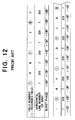
- the same point (timing) in the field I to the field IV of the television signal i.e., the position at which the recording video heads are switched is shown in Fig. 12.
- the switching occurs at the 7th line of the field I, the 319th line in the next, field II, and then the 7th line in the next, field III, and then the 319th line in the field IV.
- the burst phase is +, +, -, -, and so on. If the field-extraction is not effected, the burst phase of each field is continuous to that of the preceding field, and the reproduced image will be colored.
- the burst phase at the same point is +, -, +, -, and so on. This sequence is different from the sequence of the original burst phase, and is discontinuous, resulting in loss of color.
- phase of the chroma signal may be inverted during reproduction of the field IV and the field II, so that the burst phase at the same points will be +, +, -, -, and so on, and continuity is preserved. Then, the resultant image will be colored.
- phase of the field I and field III may be inverted. That is, if the chroma phase of every other field is inverted, the burst phase of the chroma signal at the same point will be +, +, -, -, and so on, and the resultant image will be colored.
- the reproducing device has the function of inverting the phase of the chroma signal every other field, it is necessary to provide a means for examining whether the video signal being reproduced has been field extraction recorded and therefore the chroma phase of the video signal is continuous, and it is necessary to invert the phase of the chroma signal of the reproduced video signal every other field. This will increase the cost of the device.
- the present invention has been made to solve the problems described above.
- An object is to provide a magnetic recording device which can field-extraction record the video signal of the PAL system, one out of every three fields, in such a manner that when the recorded video signal is reproduced in a mode in which every track is traced by a head just once, the image produced by the reproduced video signal is colored, without inverting the phase of the chroma signal every other field during the reproduction.
- a magnetic recording device for magnetically recording video signal of the PAL system, through field extraction comprising:
- the device may further comprise:
- the output of a reference oscillator forming a PLL for locking the phase with the input chroma signal is input to a phase inverting means, and the phase of the chroma signal is inverted by the phase inverting means every recording field, and is then low-band converted.
- recording compatibility can be achieved in the video signal of the PAL system.
- the device may further comprise:
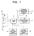
- Fig. 1 is a block diagram showing the configuration of the video signal processing circuit of a VTR according to the present invention.
- the components identical to those in Fig. 9 are denoted by identical reference numerals.
- the chroma conversion/inversion circuit 13 converts the base band chroma signal C2 into a low-band chroma C1.
- the chroma conversion/inversion circuit 13 performs B-Y axis inversion for making continuous the burst phase of the video signal to be recorded, in accordance with the head switching signal from the first switching signal generator 9.
- the chroma conversion/inversion circuit 13 converts the low-band chroma signal C1 into a baseband chroma signal C2.
- the chroma conversion/inversion circuit 13 performs B-Y axis inversion for making the burst phase of the reproduced video signal continuous.
- the chroma phase In a fast playback or speed search, in which the tracks are traced obliquely so that each head traces part only of each track, and video signal of each field is formed by assembling the video signals from fractions of different tracks, the chroma phase must be reversed at each transition from one track to another.
- the FM modulation/detection circuit 12 modulates the luminance signal Y to produce FM signals.
- the FM modulation/detection circuit 12 performs FM detection to produce a luminance signal.
- the head amplifiers 4 are used to amplify the signals to be recorded, during recording, and to amplify the reproduced signal during playback.
- the first switching signal generator 9 generates a first switching signal.
- the second switching signal generator 10 generates a second switching signal.
- the first pair of heads 2a and 2b, and a second pair of heads 3a and 3b are used to record the video signal, and to reproduce the FM signals recorded on the magnetic tape field by field.
- the input to the head amplifier 4 is switched between a first signal in field units, and a second signal in field units, according to the first switching signal of a 50 % duty ratio, generated by the first switching signal generator 9.
- the selection between the first pair of heads 2a and 2b and the second pair of heads 3a and 3b is made according to the second switching signal generator 10.
- the luminance signal Y is FM modulated by the FM modulation/detection circuit 12 to become an FM signal.
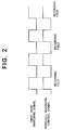
- the chroma conversion/inversion circuit 13 processes the chroma signal C2 so that its phase is alternately inverted or not inverted (passed without the inversion) about the B-Y axis, in synchronism with the first head switching signal (later described in detail with reference to Fig. 2), and converts the signal into a lower band, to produce a low-band chroma signal C1.
- the FM signal and the low-band chroma signal C1 are superimposed at the head amplifier 4, and supplied to the second heads 3a and 3b when the second head switching signal is High, and alternately supplied to the second heads 3a or 3b according to the first head switching signal, so that the television signal is field-extraction-recorded on the magnetic tape in the order of field I, field IV, field III, field II, field I, field IV, field III, field II ... .
- the signals reproduced in field units by the second heads 3a and 3b are amplified by the head amplifier 4, and are alternately output in accordance with the first head switching signal.
- the low-band chroma signal C1 is converted to a higher band, without the B-Y axis inversion, at the chroma conversion/inversion circuit 13, and reproduced as a baseband chroma signal C2.
- the FM signal is FM-detected at the FM modulation/detection circuit 12, and reproduced as a luminance signal Y.
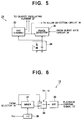
- an RP selector 14 switches between the baseband chroma signal C2 supplied from a surveillance device or the like, and a baseband chroma signal at the time of playback according to the mode set for recording (R) or playback (P).
- a bandpass filter (BPF) 15 passes the 4.43 MHz components of the output signal of the RP selector 14.
- a comb filter 16 extracts the chroma signal from the signal output from the BPF 15 during playback.
- a playback amplifying/killer circuit 17 amplifies the reproduced chroma signal and also serves as a chroma killer.
- An HL selector 18 switches between the output signal of the BPF 15 and the output signal of the playback amplifying/killer circuit 17 according to a control signal 24H-REC-H.
- a B-Y axis inversion circuit 10 is capable of inverting the phase of the baseband chroma signal of the PAL system about the B-Y axis, according to the through/inversion control signal TH/IV.
- the B-Y axis inversion circuit 19 outputs a baseband chroma signal C2 having a continuous phase.
- An HL selector 20 switches between the output of the B-Y axis inversion circuit 19, and the output of the BPF 15 according to the control signal 24H-REC-H.
- a microcomputer 21 generates the control signals 24H-REC-H, TH/IV and the like, depending on the mode of the magnetic recording and playback device.
- Fig. 4 is a flowchart showing an example of control exerted by the microcomputer 21.
- the microcomputer 21 makes judgment depending on the mode setting for the VTR (ST1), and checks if the mode is a 24-hour recording mode (ST2). If the answer is "No”, the control signal 24H-REC-H is set Low (ST3). If the answer is "Yes”, the control signal 24H-REC-H is set High and the TH/IV is generated (ST4). Recording is then started (ST5).
- a Quartz oscillating element (Quartz crystal) 22 is for oscillation at 4.43 MHz.
- a crystal oscillator (XO) 23 performs free-running oscillation to serve as a reference for the high-band conversion of the low-band chroma signal C1 during playback.
- a recording APC (automatic phase control) circuit 24 is for phase-locking a voltage-controlled oscillator 33, to be described later, with the burst signal.
- An RP selector 25 is for selective connection with the crystal oscillator 23 during playback, or with the voltage-controlled oscillator 33, to be described later, within the APC circuit 24.
- An RP selector 26 is for selectively inputting the baseband chroma signal C2 output from the HL selector 20 during recording, or the low-band chroma signal C1 during playback.
- An automatic chroma gain controller (ACC) 27 detects the level of the signal output from the RP selector 26 and controls the gain of the chroma signal so as to maintain the level constant.
- a burst gate circuit (BG) 28 extracts the burst signal from the output of the ACC 27.
- a main converter 29 performs low-band conversion of the chroma signal output from the ACC 27 by means of the reference frequency signal of 5.06 MHz during recording, and performs the high-band conversion of the low-band conversion chroma signal to a baseband chroma signal C2 by means of the low-band chroma signal and the reference frequency signal of 5.06 MHz during playback.
- a killer detection circuit 30 detects whether the burst signal of the BG 28 is PLL-locked in the recording APC circuit 24.
- a sub-converter 31 produces the reference frequency signal of 5.06 MHz from the color subcarrier frequency signal Fsc generated by the Quartz oscillator 22, and inputs the reference signal to the main converter 29.
- a killer circuit 32 outputs the low-band chroma signal C1 during recording, and applies the chroma killer in accordance with the killer output from the killer detection circuit 30.
- a voltage-controlled oscillator circuit (VXO) 33 performs voltage-controlled oscillation for locking the phase of the input chroma signal C2 during recording.
- a phase detector 35 compares the phase of the output signal from the VXO 33 and the burst signal output from the burst gate circuit 28, and smoothes the error output at a recording APC filter 34, and controls the frequency of the VXO 33 such that the phase difference is -90°.
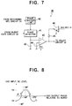
- Fig. 6 is a block diagram showing the internal configuration of the B-Y axis inversion circuit 19.
- the output of the crystal 22 is the color subcarrier frequency signal Fsc of 4.43 MHz.
- An x2 multiplier 36 multiplies the phase, cos ⁇ t, of the color subcarrier frequency signal Fsc by two to produce cos 2 ⁇ t.
- An adder (mixer) 37 multiplies, by means of a multiplier formed of a dual-stage differential amplifier, the cos ( ⁇ t ⁇ ⁇ ) where the B-Y axis is ⁇ t and the burst phase is ⁇ , by the output cos 2 ⁇ t of the x2 multiplier 36.
- a through/inversion selector 38 selects the through signal or the B-Y axis-inverted signal according to the through/inversion control signal TH/IV from the microcomputer 21.
- a bandpass filter 39 removes the components other than cos ( ⁇ t - ( ⁇ )) having been B-Y axis inverted, from the output signal of the adder 37.
- a phase shifter 40 shifts the phase of the output signal from the VXO 33 by +90°.
- a phase detector 41 performs synchronous detection of the output signal from the phase shifter 40 and the burst signal output from the burst gate circuit 28, and the DC potential at the output is lowered when the two inputs are of the same phase.
- a killer filter 42 smoothes the DC output of the phase detector 41.
- a comparator 43 compares the smoothed DC potential with the 1/2 Vcc potential, and outputs a DC potential of a High level for killer operation when the smoothed DC potential is greater than the 1/2 Vcc potential.
- Reference numeral 44 denotes a 1/2 Vcc power supply.
- a diode 45 forcibly lowers the output of the comparator 43 to Low, in a 24-hour recording mode control signal 24H-REC-H from the microcomputer 21. This is achieved because the control signal 24H-REC-H from the microcomputer 21 is inverted by a digital transistor 46. Because of the potential, the killer operation of the killer circuit 32 is released.
- the baseband chroma signal C2 input to the RP selector 14 is passed through the BPF 15 and supplied to the HL selectors 18 and 20. Since the control signal 24H-REC-H is Low, the signal is guided by the HL selector 20 to the RP selector 26, and is subjected to chroma gain control at the ACC 27. The signal is then low-band converted at the main converter 29, and passed through the killer circuit 32, and output as the low-band recording chroma signal C1 to the head amplifier 4.
- the chroma signal output from the ACC 27 to the burst gate circuit 28 is burst-gated, and is subjected to phase-control at the recording APC 24.
- the oscillation output of the VXO 33 within the APC 24 is input to the sub-converter 31, and the low-band converted recording chroma signal C1 is phase-locked with the baseband signal C2.
- the output signal of the VXO 33 is in an equilibrium when the burst signal output from the burst gate circuit 28 is lagging by 90°.
- the oscillating frequency of the VXO 33 is lowered, and the output phase of the VXO 33 is retarded. In this way, the phase difference is maintained at the equilibrium point -90°.
- the output burst signal of the burst gate circuit 28 is phase-locked is checked by the killer detection circuit 30, and if it is locked, the operation of the killer circuit 32 is interrupted. If the output signal of the VXO 33 which is locked at -90 with respect to the burst phase is phase-shifted by +90° by the phase-shifter 40, and if this phase-shifted signal is in phase with the burst phase, the output DC of the phase detector 41 is lowered.
- the chroma signal output from the BPF 15 in the same way as above is guided by the HL selector 18 to the B-Y axis inversion circuit 19, because the control signal 24H-REC-H is High. If the recording were conducted in the same way as in the 8-hour mode, the burst phase of the recorded fields would not be continuous. Therefore, if the through/inversion control signal TH/IN output from the microcomputer 21 is made High and Low alternately at every field, as shown in Fig. 2, the input chroma signal is alternately passed through or B-Y axis inverted.
- the B-Y axis inverted chroma signal is inverted relative to the output Fsc of the quartz oscillator 22 phased-locked with the input chroma signal before the inversion. Because the control signal 24H-REC-H is High, the output signal of the B-Y axis inversion circuit 19 is guided by the HL selector 20 to the RP selector 26, and is subjected to automatic chroma control at the ACC 27. The signal is then low-band converted at the main converter 29, and output via the killer circuit 32 as the recording chroma signal C1. The burst signal supplied from the ACC 27 to the burst gate circuit 28 is input to the recording APC circuit 24. In this way, feedback control loop is applied. This feedback loop is in addition to the feedback loop in the recording APC circuit 24, so that dual feedback loop is formed.
- the burst signal supplied from the ACC 27 to the burst gate circuit 28 is then input to the phase detector 41 in the killer detection circuit 30. If the output phase of the VXO 33 is a little lagging relative to -90° with respect to the burst phase of the chroma signal inverted about the B-Y axis, the terminal voltage of the recording APC filter 34 in the recording APC circuit 24 rises, and the oscillation frequency of the VXO 33 rises.
- the output phase of the VXO 33 is advanced, and accordingly the phase of Fsc input to the B-Y axis inversion circuit 19 is advanced, and the phase of the B-Y axis inverted chroma signal is also advanced, and the phase of the burst signal having passed the HL selector 20, the RP selector 26, the ACC 27 and the burst gate circuit 28 is also advanced.
- the output phase of the VXO 33 cannot advance, and the input DC level of the VXO 33 is left increased, and the output phase of the VXO 33 is retarded relatively.
- the output phase of the VXO 33 which is at -270° (or +90° ) is shifted by -90 by the phase shifter 40, resulting in -180° (or +180° ) which is an inversion, the phase detector 41 does not find that it is in phase, and the killer circuit 32 operates. But because the killer output is made Low by the diode 45, as described above, the killer operation of the killer circuit 32 is released. In the above configuration, the killer operation is forcibly released by the killer detection circuit 30. If the arrangement is such as to recognize a locked condition only when the phase detector 41 finds an in-phase or opposite-phase relationship, it may not be necessary to forcibly release the killer operation.
- the low-band chroma signal C1 is guided by the RP selector 26 to the ACC 27, and supplied to the main converter 29, where it is high-band converted.
- the signal is further passed through the RP selector 14, to the BPF 15, and is supplied to the comb filter 16, where the components other than the chroma signal is removed.
- the chroma signal is amplified at the playback amplifying/killer circuit 17, and is passed through the RP selector 18 to the B-Y axis inversion circuit 19, which passes the input signal without inversion, because the through/inversion control signal TH/IV from the microcomputer 21 is selecting "Through".
- the output of the B-Y axis inversion circuit 19 is the baseband chroma signal C2 during playback.
- the output of the free-running oscillation at 4.43 MHz at the oscillator 23 is passed through the sub-converter 31, and the main converter 29 performs high-band conversion by means of an oscillation output of 5.06 MHz.
- the circuit 19 for the B-Y axis phase inversion it is possible to share the circuit 19 for the B-Y axis phase inversion, so that the cost can be lowered and the function of coloring the images is improved.
- the intermittent recording is conducted at a tape transport speed which is one third of the LP mode.
- the invention can be applied to a situation in which the intermittent recording is conducted at a tape speed one third of the SP mode.
- the field-extraction recording is conducted every three fields.
- the difference from the 8-hour playback in Embodiment 1 is that the through/inversion control signal TH/IV from the microcomputer 21 controls "through” or "inversion” so as to preserve continuity of the phase of the color signal. That is, for instance, if the same track is reproduced repeatedly during still playback, a discontinuity occurs at the connecting points between successive fields. By alternating "through” and “inversion” at every reproduced field, the continuity is preserved and the image is colored.
- Fsc input to the B-Y axis inversion circuit 19 is the signal locked to the oscillator 23 in the free-running oscillation. Operation other than still playback, such as frame advancement, can be controlled in the same way.
- the same track is traced three time, and the video data of the same field is repeated reproduced three times to form the video data of three successive fields.
- the chroma phase of the reproduced video signal is not continuous between successive fields.
- the chroma phase of the successive fields is made continuous and the image is colored.
- the chroma phase is reversed each time there is a transition from one track to another, i.e., the head amplifier 4 switches from one head to another.
Landscapes
- Engineering & Computer Science (AREA)
- Multimedia (AREA)
- Signal Processing (AREA)
- Television Signal Processing For Recording (AREA)
- Processing Of Color Television Signals (AREA)
Applications Claiming Priority (3)
| Application Number | Priority Date | Filing Date | Title |
|---|---|---|---|
| JP9257996 | 1996-04-15 | ||
| JP92579/96 | 1996-04-15 | ||
| JP8092579A JPH09284807A (ja) | 1996-04-15 | 1996-04-15 | 磁気記録装置及び磁気記録再生装置 |
Publications (3)
| Publication Number | Publication Date |
|---|---|
| EP0802689A2 true EP0802689A2 (de) | 1997-10-22 |
| EP0802689A3 EP0802689A3 (de) | 1998-11-04 |
| EP0802689B1 EP0802689B1 (de) | 2002-07-03 |
Family
ID=14058348
Family Applications (1)
| Application Number | Title | Priority Date | Filing Date |
|---|---|---|---|
| EP19970302553 Expired - Lifetime EP0802689B1 (de) | 1996-04-15 | 1997-04-15 | Magnetische Aufnahmevorrichtung |
Country Status (3)
| Country | Link |
|---|---|
| EP (1) | EP0802689B1 (de) |
| JP (1) | JPH09284807A (de) |
| DE (1) | DE69713669T2 (de) |
Family Cites Families (1)
| Publication number | Priority date | Publication date | Assignee | Title |
|---|---|---|---|---|
| JPH05344535A (ja) * | 1992-06-05 | 1993-12-24 | Matsushita Electric Ind Co Ltd | 補強信号が付加された映像信号の磁気記録再生装置 |
-
1996
- 1996-04-15 JP JP8092579A patent/JPH09284807A/ja active Pending
-
1997
- 1997-04-15 DE DE1997613669 patent/DE69713669T2/de not_active Expired - Fee Related
- 1997-04-15 EP EP19970302553 patent/EP0802689B1/de not_active Expired - Lifetime
Also Published As
| Publication number | Publication date |
|---|---|
| EP0802689A3 (de) | 1998-11-04 |
| DE69713669D1 (de) | 2002-08-08 |
| DE69713669T2 (de) | 2003-03-13 |
| EP0802689B1 (de) | 2002-07-03 |
| JPH09284807A (ja) | 1997-10-31 |
Similar Documents
| Publication | Publication Date | Title |
|---|---|---|
| US4672470A (en) | Video signal recording and reproducing apparatus | |
| JP2937642B2 (ja) | 映像記録及び再生システム | |
| US4555735A (en) | Interconnection system between image pickup device and recording device | |
| US4100567A (en) | Compensating time-based errors in a reproduced video signal | |
| JPS6226235B2 (de) | ||
| US5003403A (en) | Recording apparatus | |
| US4326216A (en) | Synchronous color conversion system | |
| US4991026A (en) | Chrominance signal reproducing apparatus for video tape recorder | |
| KR920001105B1 (ko) | 영상신호의 기록 재생장치 | |
| EP0802689B1 (de) | Magnetische Aufnahmevorrichtung | |
| JPS63232786A (ja) | カラ−映像信号の記録方法及びその再生方法 | |
| US4809084A (en) | Apparatus for processing video signal | |
| US3845497A (en) | Colour video signal recording and reproducing system and apparatus | |
| US5802238A (en) | Circuit arrangement for processing a color signal at a carrier frequency higher than a carrier frequency at which the color signal had been recorded | |
| JPS6141294A (ja) | 記録再生装置 | |
| JP2602533B2 (ja) | 映像信号処理装置 | |
| JP2502617B2 (ja) | 映像信号記録再生装置 | |
| JP3129108B2 (ja) | 映像信号処理装置 | |
| JPS605675Y2 (ja) | Pal方式カラ−映像信号再生装置 | |
| KR880000412Y1 (ko) | 칼러 영상신호 기록장치 | |
| JP2719213B2 (ja) | スーパーインポーズ信号処理回路 | |
| JPH058630B2 (de) | ||
| JPH01191591A (ja) | 映像信号処理装置 | |
| JPS58205391A (ja) | 色信号処理回路 | |
| JPH0357394A (ja) | 磁気記録再生装置 |
Legal Events
| Date | Code | Title | Description |
|---|---|---|---|
| PUAI | Public reference made under article 153(3) epc to a published international application that has entered the european phase |
Free format text: ORIGINAL CODE: 0009012 |
|
| AK | Designated contracting states |
Kind code of ref document: A2 Designated state(s): DE FR GB IT |
|
| PUAL | Search report despatched |
Free format text: ORIGINAL CODE: 0009013 |
|
| AK | Designated contracting states |
Kind code of ref document: A3 Designated state(s): DE FR GB IT |
|
| 17P | Request for examination filed |
Effective date: 19981104 |
|
| GRAG | Despatch of communication of intention to grant |
Free format text: ORIGINAL CODE: EPIDOS AGRA |
|
| 17Q | First examination report despatched |
Effective date: 20010828 |
|
| GRAG | Despatch of communication of intention to grant |
Free format text: ORIGINAL CODE: EPIDOS AGRA |
|
| GRAG | Despatch of communication of intention to grant |
Free format text: ORIGINAL CODE: EPIDOS AGRA |
|
| GRAH | Despatch of communication of intention to grant a patent |
Free format text: ORIGINAL CODE: EPIDOS IGRA |
|
| GRAH | Despatch of communication of intention to grant a patent |
Free format text: ORIGINAL CODE: EPIDOS IGRA |
|
| GRAA | (expected) grant |
Free format text: ORIGINAL CODE: 0009210 |
|
| AK | Designated contracting states |
Kind code of ref document: B1 Designated state(s): DE FR GB IT |
|
| REF | Corresponds to: |
Ref document number: 69713669 Country of ref document: DE Date of ref document: 20020808 |
|
| ET | Fr: translation filed | ||
| PLBE | No opposition filed within time limit |
Free format text: ORIGINAL CODE: 0009261 |
|
| STAA | Information on the status of an ep patent application or granted ep patent |
Free format text: STATUS: NO OPPOSITION FILED WITHIN TIME LIMIT |
|
| 26N | No opposition filed |
Effective date: 20030404 |
|
| PGFP | Annual fee paid to national office [announced via postgrant information from national office to epo] |
Ref country code: FR Payment date: 20040408 Year of fee payment: 8 |
|
| PGFP | Annual fee paid to national office [announced via postgrant information from national office to epo] |
Ref country code: GB Payment date: 20040414 Year of fee payment: 8 |
|
| PGFP | Annual fee paid to national office [announced via postgrant information from national office to epo] |
Ref country code: DE Payment date: 20040422 Year of fee payment: 8 |
|
| PG25 | Lapsed in a contracting state [announced via postgrant information from national office to epo] |
Ref country code: IT Free format text: LAPSE BECAUSE OF NON-PAYMENT OF DUE FEES;WARNING: LAPSES OF ITALIAN PATENTS WITH EFFECTIVE DATE BEFORE 2007 MAY HAVE OCCURRED AT ANY TIME BEFORE 2007. THE CORRECT EFFECTIVE DATE MAY BE DIFFERENT FROM THE ONE RECORDED. Effective date: 20050415 Ref country code: GB Free format text: LAPSE BECAUSE OF NON-PAYMENT OF DUE FEES Effective date: 20050415 |
|
| PG25 | Lapsed in a contracting state [announced via postgrant information from national office to epo] |
Ref country code: DE Free format text: LAPSE BECAUSE OF NON-PAYMENT OF DUE FEES Effective date: 20051101 |
|
| GBPC | Gb: european patent ceased through non-payment of renewal fee |
Effective date: 20050415 |
|
| PG25 | Lapsed in a contracting state [announced via postgrant information from national office to epo] |
Ref country code: FR Free format text: LAPSE BECAUSE OF NON-PAYMENT OF DUE FEES Effective date: 20051230 |
|
| REG | Reference to a national code |
Ref country code: FR Ref legal event code: ST Effective date: 20051230 |