EP0802691A2 - Netzwerksystem für mobile Funkübertragung - Google Patents
Netzwerksystem für mobile Funkübertragung Download PDFInfo
- Publication number
- EP0802691A2 EP0802691A2 EP97302635A EP97302635A EP0802691A2 EP 0802691 A2 EP0802691 A2 EP 0802691A2 EP 97302635 A EP97302635 A EP 97302635A EP 97302635 A EP97302635 A EP 97302635A EP 0802691 A2 EP0802691 A2 EP 0802691A2
- Authority
- EP
- European Patent Office
- Prior art keywords
- server unit
- mobile radio
- base station
- electric field
- field strength
- Prior art date
- Legal status (The legal status is an assumption and is not a legal conclusion. Google has not performed a legal analysis and makes no representation as to the accuracy of the status listed.)
- Withdrawn
Links
- 238000004891 communication Methods 0.000 title claims abstract description 65
- 230000005684 electric field Effects 0.000 claims abstract description 108
- 230000005540 biological transmission Effects 0.000 claims abstract description 38
- 238000012544 monitoring process Methods 0.000 claims abstract description 35
- 230000004044 response Effects 0.000 claims abstract description 13
- 238000012545 processing Methods 0.000 claims description 17
- 238000011084 recovery Methods 0.000 claims description 4
- 238000000034 method Methods 0.000 description 22
- 238000010586 diagram Methods 0.000 description 5
- 239000000470 constituent Substances 0.000 description 1
- 238000012986 modification Methods 0.000 description 1
- 230000004048 modification Effects 0.000 description 1
Images


Classifications
-
- H—ELECTRICITY
- H04—ELECTRIC COMMUNICATION TECHNIQUE
- H04W—WIRELESS COMMUNICATION NETWORKS
- H04W36/00—Hand-off or reselection arrangements
- H04W36/02—Buffering or recovering information during reselection ; Modification of the traffic flow during hand-off
-
- H—ELECTRICITY
- H04—ELECTRIC COMMUNICATION TECHNIQUE
- H04W—WIRELESS COMMUNICATION NETWORKS
- H04W36/00—Hand-off or reselection arrangements
- H04W36/24—Reselection being triggered by specific parameters
- H04W36/30—Reselection being triggered by specific parameters by measured or perceived connection quality data
- H04W36/302—Reselection being triggered by specific parameters by measured or perceived connection quality data due to low signal strength
-
- H—ELECTRICITY
- H04—ELECTRIC COMMUNICATION TECHNIQUE
- H04W—WIRELESS COMMUNICATION NETWORKS
- H04W88/00—Devices specially adapted for wireless communication networks, e.g. terminals, base stations or access point devices
- H04W88/02—Terminal devices
- H04W88/06—Terminal devices adapted for operation in multiple networks or having at least two operational modes, e.g. multi-mode terminals
Definitions
- the present invention relates to a network system for mobile radio communication in which a network system for a mobile radio terminal is connected to a communication through a public or private radio base station to perform data communication with a server unit.
- a particular system to be described below, by way of example, in illustration of the invention minimises data losses even if slot errors or a drop in electric field strength occur between a mobile radio terminal and a public or private radio base station.
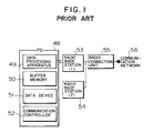
- a previously proposed network system for mobile radio communication which includes a radio connection unit 55 for selecting a line to be connected through a communication network 56, radio base stations 53 and 54 respectively installed in a plurality of unit cells, and a mobile radio terminal (to be referred to as a PS hereinafter) 48 which establishes a radio channel with a radio base station while moving.
- the PS 48 includes a buffer memory (to be referred to as a BM hereinafter) 50 for temporarily storing data in a line switching operation, a data device 51, a data processing apparatus 49, and a communication controller 52.
- the radio base station (1) 53 determines the necessity for line switching during communication between the PS 48 and the radio base station (1) 53, the radio base station (1) 53 sends a line switching notification to the radio connection unit 55, and also sends a communication interruption notification to the data processing apparatus 49.
- the data processing apparatus 49 transmits an acknowledgement signal to the radio connection unit 55 and starts to store, in the BM 50, the communication data which has been directly transmitted.
- the radio connection unit 55 receives the acknowledgement signal from the data processing apparatus 49, the communication between the PS 48 and the radio base station (1) 53 is interrupted. While the data processing apparatus 49 is storing the communication data, line switching processing is performed.
- the radio connection unit 55 sends a switching instruction to the radio base station (1) 53, that has been serving up until now, and the radio base station (2) 54 that is to serve next.
- the radio base station (1) 53 as the currently serving station sends a switching instruction to the communication controller 52.
- the communication controller 52 When these operations are complete, the communication is resumed.
- the data processing apparatus 49 reads out the data stored in the BM 50 and transmits the data to the radio base station (2) 54 through the communication controller 52. When all the data are read out from the BM 50, direct communication without the mediacy of the BM 50 is started again.
- the server unit that transmits/receives data to/from the PS has no BM for storing data. For this reason, if a hit occurs during data transmission from the server unit to the PS, data is lost.
- the radio base station must monitor the reception state of the PS so as to send a line switching instruction thereto. For this reason, line switching processing is complicated, resulting in a decrease in line switching speed.
- a PS is connected to a public radio base station (to be referred to as a public CS hereinafter) or a private radio base station (to be referred to as a private CS hereinafter) to perform data communication with a server unit in a network, and that data losses can be minimised even if slot errors or a reduction in electric field strength occur between a PS and the CS, thereby providing highly reliable data transmission.
- a public radio base station to be referred to as a public CS hereinafter
- a private radio base station to be referred to as a private CS hereinafter
- a network system for mobile radio communication (which is referred to as a network system for mobile radio communication using a public CS hereinafter) comprising a network constituted by a server unit and a client unit, a radio connection unit connected to a communication network, a public CS installed in a cell, and a PS which establishes a radio channel with the public CS while moving, the network system being adapted to perform data communication between the server unit and the PS, wherein each of the server unit and the PS includes a BM and an auxiliary storage unit which hold data, and the PS includes an electric field strength monitoring section for monitoring slot errors or a reduction in an electric field strength, stores data in the BM during data transmission to the server unit when a level based on slot errors or a reduction in electric field strength is not lower than a threshold for line switching, sends a line switching notification to the server unit, sends a line switching request to the public CS, and starts to transmit the data
- a PS in another network system for mobile radio communication using a public CS, to be described below, by way of example in illustration of the invention, includes a section for instructing a server unit to store data in a BM during data reception from the server unit when an electric field strength monitoring section determines that a level based on slot errors or a reduction in electric field strength is not lower than a threshold for line switching, a section for sending a line switching request to the public CS, and a section for notifying the server unit of completion of line switching upon reception of a response indicating completion of line switching from the public CS, and the server unit includes a section for starting to transmit the data stored in a BM.
- a PS includes a section for sending a server unit a notification indicating that preparation for line disconnection is in progress during data reception from the server unit when a level based on slot errors or a reduction in electric field strength is not lower than a threshold for line disconnection, a section for starting a timer, and a section for notifying the server unit of recovery of the electric field strength when the electric field strength is recovered within a disconnection determination time
- the server unit includes a section for storing data in a BM upon reception of the notification indicating that preparation for line disconnection is in progress from the PS, and a section for starting to transmit the data stored in a BM upon reception of a notification indicating that the electric field strength is recovered.
- a further arrangement to be described below by way of example in illustration of the present invention includes a network system for mobile radio communication using a public CS, in which a PS includes a section for storing data in a BM during data transmission to a server unit when an electric field strength monitoring section determines that a level based on slot errors or a reduction in electric field strength is not lower than a threshold for line disconnection, a section for starting a timer, and a section for starting the data stored in a BM when the electric field strength is recovered within a predetermined disconnection determination time.
- the PS when the electric field strength is not recovered within the disconnection determination time, the PS can output a line disconnection request to the public CS and can perform termination processing in preparation for power off of the PS upon completion of line disconnection.
- a still further network system for mobile radio communication to be described below includes a private network constituted by a radio management server, a server unit, and a client unit, a private CS installed in a cell, and a PS which establishes a radio channel with the private CS while moving, the system being adapted to perform data communication between the server unit and the PS, each of the server unit and the PS including a BM and an auxiliary storage unit which hold data, and the PS including an electric field strength monitoring section for monitoring slot errors or a reduction in electric field strength, a section for storing data in the BM during data transmission to the server unit when a level based on slot errors or a reduction in electric field strength is not lower than a threshold for line switching, a section for sending a line switching notification to the server unit, a section for sending a line switching request to the private CS, and a section for starting to transmit the data stored in the BM upon reception of a response indicating completion of line switching from the private CS.
- a PS includes a section for instructing a server unit to store data in a BM during data reception from the server unit when an electric field strength monitoring section determines that a level based on slot errors or a reduction in electric field strength is not lower than a threshold for line switching, a section for sending a line switching request to the private CS, and a section for notifying the server unit of completion of line switching upon reception of a response indicating completion of line switching from the private CS, and the server unit includes a section for changing a private CS destination ID of the data stored in a BM to a private CS destination ID after line switching, and a section for starting to transmit the stored data.
- a PS includes a section for notifying a server unit that preparation for line disconnection is in progress during data reception from the server unit when an electric field strength monitoring section determines that a level based on slot errors or a reduction in electric field strength is not lower than a threshold for line switching, a section for starting a timer, and a section for notifying the server unit of recovery of the electric field strength when the electric field strength is recovered within a disconnection determination time
- the server unit includes a section for storing data in a BM upon reception of a notification indicating that preparation for line disconnection is in progress from the PS, and a section for starting to transmit the data stored in the BM upon reception of a notification indicating that the electric field strength is recovered.
- a PS includes a section for storing data in a BM during data transmission to a server unit when an electric field strength monitoring section determines that a level based on slot errors or a reduction in electric field strength is not lower than a threshold for line disconnection, a section for starting a timer, and a section for starting to transmit the data stored in a BM when the electric field strength is recovered within a predetermined disconnection determination time.
- the PS can output a line disconnection request to the public CS when the electric field strength is not recovered within the disconnection determination time, and can perform termination processing in preparation for power off of the PS upon completion of line disconnection.
- a network system for mobile radio communication including both a mobile radio network system using a public CS and a mobile radio network system using a private CS will also be described below by way of example in illustration of the invention, in which a PS includes a section for switching connection to the public CS or the private CS.
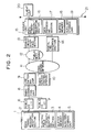
- a network system for mobile radio communication will be described below with reference to Fig. 2. Assume that a slot error or a reduction in electric field strength occurs between a PS and a public CS during a wide-area information service in which, for example, the user transmits/receives data, outside the office, to/from a server unit connected to a network such as an office LAN through a high-speed network such as an ISDN or a public network such as a telephone line.
- a network such as an office LAN through a high-speed network such as an ISDN or a public network such as a telephone line.
- the first system comprises a network 21 constituted by a server unit 15 and a client unit 20, a line switching unit 9 to which the network 21 is connected through a digital line interface section 14 and a high-speed network 11 or through an analog circuit interface section 13, a public network 12, and the high-speed network 11, a radio connection unit 8 for generating position information on the basis of a PS position registration request from a public CS (1) 6 or a public CS (2) 7, a radio service control station 10 for recording the position information, and a group of unit cells.
- Each unit cell comprises the public CS (1) 6 or the public CS (2) 7 and a PS 1 which establishes a channel with the public CS (1) 6 or the public CS (2) 7 in the unit cell while moving.
- the PS 1 has a means of requesting the public CS (1) 6 to perform line switching and disconnection.
- the PS 1 includes a data transmission/reception section 2 for transmitting/receiving data, an electric field strength monitoring section 3 for monitoring a slot error or a reduction in electric field strength, a BM 4 for temporarily storing data to be communicated, and an auxiliary storage unit 5 for saving data.
- the server unit 15 includes a data processing section 17 for analyzing a request from the PS 1 and processing necessary data, a data transmission/reception section 16 for transmitting/receiving data, a BM 18 for temporarily storing data to be communicated, and an auxiliary storage unit 19.
- the digital line interface section 14 provides the interface between the high-speed network 11 and the server unit 15.
- the analog circuit interface section 13 provides the interface between the public network 12 and the server unit 15.
- the digital line interface section 14 an assembly of a terminal adaptor, a line controller, and an ISDN board is available.
- TDMA Time Division Multiple Access
- TDD Time Division Duplex
- the thresholds for line switching and line disconnection are specified in advance between the PS and the radio base station, and both the level obtained by monitoring a reduction in electric field strength instead of slot errors and the level based on a combination of monitoring operations for slot errors and a reduction in electric field strength can be compared with the above thresholds. Since a method of monitoring slot errors and a reduction in electric field strength is a known technique in the radio communication schemes, and is not a constituent element of the present invention, a description thereof will be omitted.
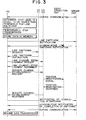
- the level based on slot errors or a reduction in electric field strength is equal to or higher than the threshold for line switching, and data is to be transmitted to the server unit.
- the procedure required between the PS, the public CS, and the server unit in this case will be described as the first mode of the first system with reference to Fig. 3.
- the data transmission/reception section 2 When the electric field strength monitoring section 3 of the PS 1 determines that the level based on slot errors or a reduction in electric field strength is equal to or higher than the threshold for line switching, the data transmission/reception section 2 temporarily stops the transmission, and stores, in the BM 4, the data which cannot be transmitted. The data transmission/reception section 2 then sends a line switching notification to the server unit 15. Upon reception of an acknowledgement from the server unit 15, the data transmission/reception section 2 requests the public CS (1) 6 to perform line switching.
- the PS 1 Upon reception of the line switching instruction from the public CS (1) 6, the PS 1 sends the public CS (2) 7 a request for establishing a channel for transferring information required to connect the radio base station and the PS (to be referred to as a link line establishment request hereinafter).
- the PS 1 sends the public CS (2) 7 a request for establishing a channel used to transmit/receive data (to be referred to as a service channel establishment request hereinafter).
- the public CS (2) 7 Upon reception of the request, the public CS (2) 7 sends a position registration signal to the radio connection unit 8. The signal is then registered in the radio service control station 10 through the radio connection unit 8 and the line switching unit 9.
- the PS 1 Upon reception of a response signal indicating the completion of line switching from the public CS (2) 7, the PS 1 notifies the server unit 15 of the completion of line switching. Upon reception of an acknowledgement from the server unit 15, the PS 1 starts to transmit the data stored in the BM 4.
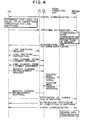
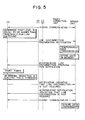
- the PS 1 When the electric field strength monitoring section 3 of the PS 1 determines that the level based on slot errors or a reduction electric field strength is equal to or higher than the threshold for line switching, the PS 1 sends a line switching notification to the server unit 15.
- the data transmission/reception section 16 temporarily stops the transmission, stores, in the BM 18, the data which cannot be transmitted, and sends the PS 1 an acknowledgement to the line switching notification.
- the PS 1 Upon reception of the acknowledgement, the PS 1 sends a line switching request to the public CS (1) 6.
- the PS 1 Upon reception of a line switching instruction from the public CS (1) 6, the PS 1 sends a link channel establishment request to the public CS (2) 7. When a link channel is established, the PS 1 sends a service channel establishment request to the public CS (2) 7. Upon reception of the request, the public CS (2) 7 sends a position registration signal to the radio connection unit 8. The signal is then registered in the radio service control station 10 through the radio connection unit 8 and the line switching unit 9. Upon reception of a response indicating the completion of line switching from the public CS (2) 7, the PS 1 notifies the server unit 15 of the completion of line switching. The server unit 15 sends an acknowledgement to the PS 1 and starts to transmit the data stored in the BM 18.
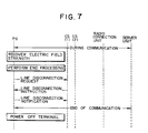
- the PS 1 sends a line disconnection preparation notification to the server unit 15.
- the data transmission/reception section 16 temporarily stops the transmission, stores, in the BM 18, the data which cannot be transmitted, and sends an acknowledgement to the PS 1.
- the PS 1 starts the timer and checks whether the electric field strength is recovered within a predetermined disconnection determination time. If the electric field strength is recovered within the predetermined disconnection determination time, the PS 1 notifies the server unit 15 that line disconnection is not required. The server unit 15 then sends an acknowledgement to the PS 1, and starts to transmit the data stored in the BM 18.
- the data transmission/reception section 2 temporarily stops the transmission, stores, in the BM 4, the data which cannot be transmitted, and sends a line disconnection preparation notification to the server unit 15.
- the PS 1 Upon reception of an acknowledgement from the server unit 15, the PS 1 starts the timer, and checks whether the electric field strength is recovered within a predetermined disconnection determination time. If the electric field strength is recovered within the disconnection determination time, the PS 1 notifies the server unit 15 that line disconnection is not required.
- the PS 1 starts to transmit the data stored in the BM 4.
- the PS 1 sends a line disconnection request to the public CS (1) 6.
- the PS 1 Upon reception of a line disconnection instruction from the public CS (1) 6, the PS 1 disconnects the line, and notifies the public CS (1) 6 that the line is disconnected.
- the PS 1 is then powered off.
- the PS 1 is powered on again, the operation state indicated by the information saved in the auxiliary storage unit 5 is restored.
- the PS 1 retransmits the data saved in the auxiliary storage unit 5.
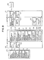
- Fig. 8 is a block diagram showing the overall arrangement of the second system of the present invention.
- a network system for mobile radio communication will be described below. Assume that a slot error or a reduction in electric field strength occurs between a PS and a private CS during a local information service system or the like in which, for example, data is transmitted/received to/from a server unit connected to a network in facilities such as an amusement park without the mediacy of a line.
- the second system comprises a network A23 constituted by a radio management server A26, a group of unit cells, a server unit A27, and a client unit (1) 29, and a network B31 constituted by a radio management server B32, a group of unit cells, a server unit B33, and a client unit (2) 34.
- Each unit cell is constituted by a private CS (1) 24 and a CS (2) 25, or a CS (3) 36 and a CS (4) 37, and a PS (1) 22 or a PS (2) 38 which establishes a channel with a private CS in the unit cell while moving.
- the PS (1) 22 or the PS (2) 38 has a means of requesting a private CS to perform line switching and disconnection.
- Each PS includes a data transmission/reception section 2 for transmitting/receiving data, an electric field strength monitoring section 3 for monitoring slot errors or a reduction in electric field strength due to interference, a BM 4 for temporarily storing data to be communicated, and an auxiliary storage unit 5 for saving data.
- Each of the server units 27 and 33 includes a data processing section 17 for analyzing a request from a corresponding one of the PS (1) 22 and the PS (2) 38, and processing necessary data, a data transmission/reception section 16 for transmitting/receiving data, a BM 18 for temporarily storing data to be communicated, an auxiliary storage unit 19, and an ID changing section 28.
- the address of the PS is registered in the radio management server in advance, and the radio management server can transmit data to the PS by changing the destination of the data on the basis of the address.
- the level based on slot errors or a reduction in electric field strength is equal to or higher than a threshold for line switching, and data is to be transmitted to the server unit.
- the procedure required between the PS, the private CS, and the server unit in this case will be described below as the first mode of the second system with reference to Fig. 9.
- the data transmission/reception section 2 temporarily stops the transmission, stores, in the BM 4, the data which cannot be transmitted, and sends a line switching notification to the server unit A27.
- the PS (1) 22 Upon reception of an acknowledgement from the server unit A27, the PS (1) 22 sends a line switching request to the private CS (1) 24.
- the PS (1) 22 Upon reception of a line switching instruction from the private CS (1) 24, the PS (1) 22 sends a link channel establishment request to the private CS (2) 25. When a link channel is established, the PS (1) 22 sends a service channel establishment request to the private CS (2) 25.
- the private CS (2) 25 requests the radio management server A26 to change the ID of the PS (1) 22.
- the radio management server A26 changes the ID of the PS (1) 22, holds the ID data, and notifies the server unit A27 that the ID has been changed.
- the PS (1) 22 Upon reception of a response indicating the completion of line switching from the private CS (2) 25, the PS (1) 22 notifies the server unit A27 of the completion of line switching.
- the PS (1) 22 Upon reception of an acknowledgement from the server unit A27, the PS (1) 22 starts to transmit the data stored in the BM 4.
- the PS (1) 22 sends a line switching notification to the server unit A27.
- the data transmission/reception section 16 temporarily stops the transmission, stores, in the BM 18, the data which cannot be transmitted, and sends the PS (1) 22 an acknowledgement to the line switching notification.
- the PS (1) 22 Upon reception of the acknowledgement, the PS (1) 22 sends a line switching request to the private CS (1) 24. Upon reception of a line switching instruction from the private CS (1) 24, the PS (1) 22 sends a link channel establishment request to the private CS (2) 25. When a link channel is established, the PS (1) 22 sends a service channel establishment request to the private CS (2) 25.
- the private CS (2) 25 requests the radio management server A26 to change the ID of the PS (1) 22.
- the radio management server A26 changes the ID of the PS (1) 22, and holds the ID data.
- the radio management server A26 notifies the server unit A27 that the ID is changed.
- the PS (1) 22 Upon reception of a response indicating the completion of line switching from the private CS (2) 25, the PS (1) 22 notifies the server unit A27 of the completion of line switching.
- the server unit A27 sends an acknowledgement to the PS (1) 22.
- the ID changing section 28 then changes the destination of the data stored in the BM 18, and starts to transmit the data.
- the PS (1) 22 sends a line switching preparation notification to the server unit A27.
- the data transmission/reception section 16 temporarily stops the transmission, stores, in the BM 18, the data which cannot be transmitted, and sends an acknowledgement to the PS (1) 22.
- the PS (1) 22 starts a timer, and checks whether the electric field strength is recovered within a predetermined disconnection determination time. If the electric field strength is recovered within the disconnection determination time, the PS (1) 22 notifies the server unit A27 that line disconnection is not required.
- the server unit A27 sends an acknowledgement to the PS (1) 22, and starts to transmit the data stored in the BM 18.
- the data transmission/reception section 2 temporarily stops the transmission, stores, in the BM 4, the data which cannot be transmitted, and sends a line disconnection notification to the server unit A27.
- the PS (1) 22 Upon reception of an acknowledgement from the server unit A27, the PS (1) 22 starts the timer, and checks whether the electric field strength is recovered within a predetermined disconnection determination time. If the electric field strength is recovered within the disconnection determination time, the PS (1) 22 notifies the server unit A27 that line disconnection is not required. Upon reception of an acknowledgement from the server unit A27, the PS (1) 22 starts to transmit the data stored in the BM 4.
- the PS (1) 22 then sends a line disconnection request to the private CS (1) 24.
- the PS (1) 22 disconnects the line, and notifies the private CS (1) 24 that the line is disconnected.
- the PS (1) 22 is then powered off. When the PS (1) 22 is powered on again, the operation state indicated by the information saved in the auxiliary storage unit 5 is restored. If the electric field strength is recovered, the PS (1) 22 retransmits the data saved in the auxiliary storage unit 5.
- Fig. 14 is a block diagram showing the overall arrangement of the third system of the present invention.
- the third system comprises first and second systems.
- the first system includes a line switching unit 9 to which a network 46 constituted by a server unit 15 and a client unit 47 is connected through a digital line interface section 14 and high-speed network 11 or through an analog circuit interface section 13, a public network 12, and the high-speed network 11, a radio connection unit 8 for generating position information on the basis of a position registration request from a public CS 39, a radio service control station 10 for registering the position information, and a group of unit cells each constituted by a PS 1 which establishes a channel with the public CS 39 while moving, and the public CS 39.
- the second system includes a network 40 constituted by a radio management server 42, a server unit 43, and a client unit 44 and a group of unit cells each constituted by the PS 1 which establishes a channel with a private CS 41 while moving, and the private CS 41.
- the PS 1 when the PS 1 is powered on, a channel is established between the PS 1 and the private CS 41 of the second system which is located in the unit cell.
- the data transmission/reception section 2 of the PS 1 detects the start of connection processing with respect to a public CS, thereby connecting a channel between the PS 1 and the public CS 39 of the first system which is located in the unit cell.
- the PS 1 can transmit/receive data to/from the server unit 43 connected to the network inside the same facilities, or can transmit/receive data to/from the server unit 15 connected to a network such as a LAN in other facilities inside the office.
Landscapes
- Engineering & Computer Science (AREA)
- Computer Networks & Wireless Communication (AREA)
- Signal Processing (AREA)
- Mobile Radio Communication Systems (AREA)
Applications Claiming Priority (3)
| Application Number | Priority Date | Filing Date | Title |
|---|---|---|---|
| JP96696/96 | 1996-04-18 | ||
| JP8096696A JP2859204B2 (ja) | 1996-04-18 | 1996-04-18 | 移動無線ネットワークシステム |
| JP9669696 | 1996-04-18 |
Publications (2)
| Publication Number | Publication Date |
|---|---|
| EP0802691A2 true EP0802691A2 (de) | 1997-10-22 |
| EP0802691A3 EP0802691A3 (de) | 2003-11-12 |
Family
ID=14171941
Family Applications (1)
| Application Number | Title | Priority Date | Filing Date |
|---|---|---|---|
| EP97302635A Withdrawn EP0802691A3 (de) | 1996-04-18 | 1997-04-17 | Netzwerksystem für mobile Funkübertragung |
Country Status (5)
| Country | Link |
|---|---|
| US (1) | US6173184B1 (de) |
| EP (1) | EP0802691A3 (de) |
| JP (1) | JP2859204B2 (de) |
| AU (1) | AU731118B2 (de) |
| CA (1) | CA2202565C (de) |
Cited By (8)
| Publication number | Priority date | Publication date | Assignee | Title |
|---|---|---|---|---|
| WO2000018153A1 (de) * | 1998-09-21 | 2000-03-30 | Mannesmann Ag | Kanalzuweisung eines kanals für datencalls mit unterschiedlichem nutz-/störsignal(n/s)-verhältnis als bei kanälen für sprach-calls in mobilfunknetzen |
| EP0946068A3 (de) * | 1998-03-26 | 2000-10-18 | Nec Corporation | Verfahren und System zur Funkdatenübertragung |
| EP0920218A3 (de) * | 1997-11-25 | 2001-03-14 | Mitsubishi Denki Kabushiki Kaisha | Datenvermittlungsvorrichtung zum Schalten erhaltener Daten ohne die Codiereinheit zu verändern |
| EP1283649A1 (de) * | 2001-08-08 | 2003-02-12 | Siemens Aktiengesellschaft | Verfahren und Anordnung für effektive Handover in einem Datenübertragungssystem bei Datenübertragungen in Abwärtsrichtung |
| WO2003015441A1 (de) * | 2001-08-08 | 2003-02-20 | Siemens Aktiengesellschaft | Verfahren und anordnung für effektive handover in einem datenübertragungssystem bei datenübertragungen in abwärtsrichtung |
| EP1848227A1 (de) * | 2006-04-18 | 2007-10-24 | Samsung Electronics Co., Ltd. | Verfahren und Vorrichtung zur Kontrolle der Übertragung einer Meldung während der Weiterleitung in einem mobilen Kommunikationsendgerät |
| EP2276179A1 (de) * | 2002-04-30 | 2011-01-19 | Panasonic Corporation | Drahtloses Kommunikationsgerät |
| CN102123360A (zh) * | 2010-01-11 | 2011-07-13 | 联发科技股份有限公司 | 无线消息传递方法及移动站 |
Families Citing this family (8)
| Publication number | Priority date | Publication date | Assignee | Title |
|---|---|---|---|---|
| JP3107041B2 (ja) * | 1998-04-28 | 2000-11-06 | 日本電気株式会社 | 無線データ通信方法及び装置 |
| JP3620010B2 (ja) | 1998-05-22 | 2005-02-16 | 富士通株式会社 | 無線通信システムで用いられる装置とプログラム記録媒体 |
| US7310529B1 (en) * | 2000-01-24 | 2007-12-18 | Nortel Networks Limited | Packet data traffic control for cellular wireless networks |
| JP2001285508A (ja) * | 2000-03-30 | 2001-10-12 | Sogo Keibi Hosho Co Ltd | 警備通信システム |
| EP1345463B1 (de) | 2002-03-13 | 2009-09-23 | NTT DoCoMo, Inc. | Mobiler Knoten, Mobilkommunikationssystem, und Kommunikationssteuerungsprogramm |
| KR20100118146A (ko) * | 2008-03-27 | 2010-11-04 | 쿄세라 코포레이션 | 무선 통신 장치 및 통신 장치 |
| US8254905B2 (en) * | 2008-07-07 | 2012-08-28 | Cisco Technology, Inc. | Service monitoring and disconnection notification in a wireless gateway device |
| JP5441113B2 (ja) * | 2009-11-06 | 2014-03-12 | シャープ株式会社 | シンクライアントシステム |
Citations (1)
| Publication number | Priority date | Publication date | Assignee | Title |
|---|---|---|---|---|
| EP0643543A2 (de) * | 1993-09-10 | 1995-03-15 | Alcatel SEL Aktiengesellschaft | Nahbereichfunktelefonsystem |
Family Cites Families (16)
| Publication number | Priority date | Publication date | Assignee | Title |
|---|---|---|---|---|
| JPH0683134B2 (ja) | 1983-05-18 | 1994-10-19 | 株式会社日立製作所 | 移動無線通信方法 |
| DE3886967T2 (de) * | 1987-03-20 | 1994-07-07 | Hitachi Ltd | Tragbares schnurloses Kommunikationssystem und Verfahren. |
| US4887265A (en) * | 1988-03-18 | 1989-12-12 | Motorola, Inc. | Packet-switched cellular telephone system |
| US5367558A (en) * | 1988-09-23 | 1994-11-22 | Motorola, Inc. | Cellular cordless telephone |
| US4912756A (en) * | 1989-04-07 | 1990-03-27 | Unilink Corporation | Method and apparatus for error-free digital data transmission during cellular telephone handoff, etc. |
| US5159592A (en) * | 1990-10-29 | 1992-10-27 | International Business Machines Corporation | Network address management for a wired network supporting wireless communication to a plurality of mobile users |
| JP3252487B2 (ja) * | 1992-10-23 | 2002-02-04 | 松下電器産業株式会社 | セルラ無線電話システム |
| HUT71357A (en) * | 1993-07-02 | 1995-11-28 | Motorola Inc | Method and apparatus for transferring a radiotelephone call from one coverage area to another |
| US5446736A (en) * | 1993-10-07 | 1995-08-29 | Ast Research, Inc. | Method and apparatus for connecting a node to a wireless network using a standard protocol |
| US5794141A (en) * | 1994-02-24 | 1998-08-11 | Gte Mobile Comm Servinc | Multi-mode communication network with handset-assisted cordless base station activation |
| US5594951A (en) * | 1994-10-07 | 1997-01-14 | Motorola, Inc. | Method and apparatus for saving power in a radiotelephone |
| WO1996021329A1 (en) * | 1994-12-30 | 1996-07-11 | Telefonaktiebolaget Lm Ericsson | System and method relating to cellular communications |
| US5850517A (en) * | 1995-08-31 | 1998-12-15 | Oracle Corporation | Communication link for client-server having agent which sends plurality of requests independent of client and receives information from the server independent of the server |
| US5809415A (en) * | 1995-12-11 | 1998-09-15 | Unwired Planet, Inc. | Method and architecture for an interactive two-way data communication network |
| WO1998016074A2 (en) * | 1996-10-09 | 1998-04-16 | Alcatel Usa Sourcing, L.P. | Call management in a wireless telecommunications system |
| US5966663A (en) * | 1997-01-14 | 1999-10-12 | Ericsson Messaging Systems Inc. | Data communications protocol for facilitating communications between a message entry device and a messaging center |
-
1996
- 1996-04-18 JP JP8096696A patent/JP2859204B2/ja not_active Expired - Fee Related
-
1997
- 1997-04-14 CA CA002202565A patent/CA2202565C/en not_active Expired - Fee Related
- 1997-04-16 US US08/840,797 patent/US6173184B1/en not_active Expired - Fee Related
- 1997-04-17 AU AU18941/97A patent/AU731118B2/en not_active Ceased
- 1997-04-17 EP EP97302635A patent/EP0802691A3/de not_active Withdrawn
Patent Citations (1)
| Publication number | Priority date | Publication date | Assignee | Title |
|---|---|---|---|---|
| EP0643543A2 (de) * | 1993-09-10 | 1995-03-15 | Alcatel SEL Aktiengesellschaft | Nahbereichfunktelefonsystem |
Cited By (13)
| Publication number | Priority date | Publication date | Assignee | Title |
|---|---|---|---|---|
| EP0920218A3 (de) * | 1997-11-25 | 2001-03-14 | Mitsubishi Denki Kabushiki Kaisha | Datenvermittlungsvorrichtung zum Schalten erhaltener Daten ohne die Codiereinheit zu verändern |
| US6385212B1 (en) | 1997-11-25 | 2002-05-07 | Mitsubishi Denki Kabushiki Kaisha | Data switching apparatus for switching received data without changing coding unit |
| EP0946068A3 (de) * | 1998-03-26 | 2000-10-18 | Nec Corporation | Verfahren und System zur Funkdatenübertragung |
| WO2000018153A1 (de) * | 1998-09-21 | 2000-03-30 | Mannesmann Ag | Kanalzuweisung eines kanals für datencalls mit unterschiedlichem nutz-/störsignal(n/s)-verhältnis als bei kanälen für sprach-calls in mobilfunknetzen |
| EP1283649A1 (de) * | 2001-08-08 | 2003-02-12 | Siemens Aktiengesellschaft | Verfahren und Anordnung für effektive Handover in einem Datenübertragungssystem bei Datenübertragungen in Abwärtsrichtung |
| WO2003015441A1 (de) * | 2001-08-08 | 2003-02-20 | Siemens Aktiengesellschaft | Verfahren und anordnung für effektive handover in einem datenübertragungssystem bei datenübertragungen in abwärtsrichtung |
| US8588159B2 (en) | 2002-04-30 | 2013-11-19 | Harris Corporation | Radio communication apparatus including the use of non-transmission information |
| EP2276179A1 (de) * | 2002-04-30 | 2011-01-19 | Panasonic Corporation | Drahtloses Kommunikationsgerät |
| US7903606B2 (en) | 2002-04-30 | 2011-03-08 | Panasonic Corporation | Radio communication apparatus employing non-transmission information indicative of not transmitting transmission data when transmission data is not sent corresponding to a quality indication signal or when the transmission data cannot be transmitted to the communicating station |
| EP1848227A1 (de) * | 2006-04-18 | 2007-10-24 | Samsung Electronics Co., Ltd. | Verfahren und Vorrichtung zur Kontrolle der Übertragung einer Meldung während der Weiterleitung in einem mobilen Kommunikationsendgerät |
| CN102123360A (zh) * | 2010-01-11 | 2011-07-13 | 联发科技股份有限公司 | 无线消息传递方法及移动站 |
| US9100885B2 (en) | 2010-01-11 | 2015-08-04 | Mediatek Inc. | Wireless messaging method and mobile station |
| US9629043B2 (en) | 2010-01-11 | 2017-04-18 | Mediatek Inc. | Wireless messaging method and mobile station |
Also Published As
| Publication number | Publication date |
|---|---|
| CA2202565A1 (en) | 1997-10-18 |
| AU731118B2 (en) | 2001-03-22 |
| JP2859204B2 (ja) | 1999-02-17 |
| EP0802691A3 (de) | 2003-11-12 |
| CA2202565C (en) | 2002-11-19 |
| JPH09284211A (ja) | 1997-10-31 |
| AU1894197A (en) | 1997-10-23 |
| US6173184B1 (en) | 2001-01-09 |
Similar Documents
| Publication | Publication Date | Title |
|---|---|---|
| EP0802691A2 (de) | Netzwerksystem für mobile Funkübertragung | |
| US6590875B1 (en) | Radio data communication technique for maintaining a connection between a mobile radio transmission device and a server during a communication interruption | |
| EP0800298A2 (de) | Ziel-Einrichtung und Verfahren zur Herstellung eines Übertragungsweges in einem vernetzten Kommunikationssystem | |
| EP0521610A2 (de) | Digitales zellulares Überlagerungsnetz | |
| EP0840533A2 (de) | Verfahren und System zur Kommunikation mit Ferneinheiten in einem Kommunikationssystem | |
| CN111464996B (zh) | 一种基于网络的dect资源协调方法和系统 | |
| EP0899899A2 (de) | Gerät und Verfahren zur Teilung eines Signalisierungskanals | |
| CN101834739B (zh) | 一种直放站网管系统及直放站网管通信方法和装置 | |
| EP0450973B1 (de) | Funkkommunikationsanlage | |
| JPH09214545A (ja) | ネットワーク通信制御方式 | |
| KR100605369B1 (ko) | 무선데이터망접속제어방법및무선데이터전송시스템 | |
| JPH11275143A (ja) | 無線データ通信方法及び無線データ通信装置 | |
| JP2001036527A (ja) | ネットワーク課金データ管理システム及びその管理方法 | |
| KR0137754B1 (ko) | 자동판매기의 정보수집장치 | |
| JP3356710B2 (ja) | 移動通信システムの回線選択方法及び移動通信システム | |
| JPH0918956A (ja) | 無線データ通信システム | |
| JP2980069B2 (ja) | 無線パケット伝送システム | |
| JPH0129110B2 (de) | ||
| JP3136884B2 (ja) | ディジタル移動通信システムおよびデータ伝送方法 | |
| JP3285498B2 (ja) | 無線通信ネットワークシステム | |
| JP2002217822A (ja) | 無線通信システム及びそのシステムにおける加入者局 | |
| EP0916197B1 (de) | Verfahren und anordnung zur datenzuteilung von benutzern eines dect systems | |
| JP3321360B2 (ja) | 移動通信システム | |
| JP3105675B2 (ja) | 移動体通信システムにおけるスケルチ断時の再発信方式 | |
| JPH1155759A (ja) | データ収集システム、及びこのシステムで使用される通信装置及び方法 |
Legal Events
| Date | Code | Title | Description |
|---|---|---|---|
| PUAI | Public reference made under article 153(3) epc to a published international application that has entered the european phase |
Free format text: ORIGINAL CODE: 0009012 |
|
| AK | Designated contracting states |
Kind code of ref document: A2 Designated state(s): FR GB |
|
| PUAL | Search report despatched |
Free format text: ORIGINAL CODE: 0009013 |
|
| AK | Designated contracting states |
Kind code of ref document: A3 Designated state(s): FR GB |
|
| 17P | Request for examination filed |
Effective date: 20031013 |
|
| 17Q | First examination report despatched |
Effective date: 20040206 |
|
| STAA | Information on the status of an ep patent application or granted ep patent |
Free format text: STATUS: THE APPLICATION IS DEEMED TO BE WITHDRAWN |
|
| 18D | Application deemed to be withdrawn |
Effective date: 20040617 |