EP0802764B1 - Vorrichtung und verfahren zum wärmen einer fütterung für schuhwerk - Google Patents
Vorrichtung und verfahren zum wärmen einer fütterung für schuhwerk Download PDFInfo
- Publication number
- EP0802764B1 EP0802764B1 EP96932634A EP96932634A EP0802764B1 EP 0802764 B1 EP0802764 B1 EP 0802764B1 EP 96932634 A EP96932634 A EP 96932634A EP 96932634 A EP96932634 A EP 96932634A EP 0802764 B1 EP0802764 B1 EP 0802764B1
- Authority
- EP
- European Patent Office
- Prior art keywords
- nozzle
- boot
- fitting
- heating device
- hot air
- Prior art date
- Legal status (The legal status is an assumption and is not a legal conclusion. Google has not performed a legal analysis and makes no representation as to the accuracy of the status listed.)
- Expired - Lifetime
Links
- 238000010438 heat treatment Methods 0.000 title claims abstract description 38
- 238000000034 method Methods 0.000 title claims abstract description 16
- 239000000463 material Substances 0.000 claims description 9
- 230000000903 blocking effect Effects 0.000 claims 2
- 238000003856 thermoforming Methods 0.000 abstract description 13
- 210000002683 foot Anatomy 0.000 description 13
- 210000003423 ankle Anatomy 0.000 description 2
- 208000037516 chromosome inversion disease Diseases 0.000 description 2
- 239000010985 leather Substances 0.000 description 2
- 229920003023 plastic Polymers 0.000 description 2
- 239000004033 plastic Substances 0.000 description 2
- 241000195940 Bryophyta Species 0.000 description 1
- 239000004698 Polyethylene Substances 0.000 description 1
- 241000135309 Processus Species 0.000 description 1
- 230000006978 adaptation Effects 0.000 description 1
- 230000005540 biological transmission Effects 0.000 description 1
- 238000007664 blowing Methods 0.000 description 1
- 238000010276 construction Methods 0.000 description 1
- 230000006866 deterioration Effects 0.000 description 1
- 238000009792 diffusion process Methods 0.000 description 1
- 230000000694 effects Effects 0.000 description 1
- 230000035515 penetration Effects 0.000 description 1
- 230000002093 peripheral effect Effects 0.000 description 1
- -1 polyethylene Polymers 0.000 description 1
- 229920000573 polyethylene Polymers 0.000 description 1
Images

Classifications
-
- B—PERFORMING OPERATIONS; TRANSPORTING
- B29—WORKING OF PLASTICS; WORKING OF SUBSTANCES IN A PLASTIC STATE IN GENERAL
- B29D—PRODUCING PARTICULAR ARTICLES FROM PLASTICS OR FROM SUBSTANCES IN A PLASTIC STATE
- B29D35/00—Producing footwear
-
- A—HUMAN NECESSITIES
- A43—FOOTWEAR
- A43B—CHARACTERISTIC FEATURES OF FOOTWEAR; PARTS OF FOOTWEAR
- A43B7/00—Footwear with health or hygienic arrangements
- A43B7/14—Footwear with health or hygienic arrangements with foot-supporting parts
- A43B7/28—Adapting the inner sole or the side of the upper of the shoe to the sole of the foot
-
- A—HUMAN NECESSITIES
- A47—FURNITURE; DOMESTIC ARTICLES OR APPLIANCES; COFFEE MILLS; SPICE MILLS; SUCTION CLEANERS IN GENERAL
- A47L—DOMESTIC WASHING OR CLEANING; SUCTION CLEANERS IN GENERAL
- A47L23/00—Cleaning footwear
- A47L23/20—Devices or implements for drying footwear, also with heating arrangements
- A47L23/205—Devices or implements for drying footwear, also with heating arrangements with heating arrangements
-
- A—HUMAN NECESSITIES
- A63—SPORTS; GAMES; AMUSEMENTS
- A63C—SKATES; SKIS; ROLLER SKATES; DESIGN OR LAYOUT OF COURTS, RINKS OR THE LIKE
- A63C5/00—Skis or snowboards
- A63C5/12—Making thereof; Selection of particular materials
Definitions
- the subject of the present invention is a method and a heating device for the purpose of thermoforming the inside of a shoe with a rigid external upper.
- such shoes such as for example ski boots, or even shoes mountain, ice skating shoes, inline skating shoes, ... etc, must have a rod external, generally constituted by a rigid plastic shell but which can also be thick and rigid leather for mountain shoes for example, which must ensure the whole ankle, and in particular avoid twisting the ankle, and allow good transmission of the forces exerted by the foot, either for driving the ski or the sliding member, or for handling on slopes for mountain walking.
- a rod external generally constituted by a rigid plastic shell but which can also be thick and rigid leather for mountain shoes for example, which must ensure the whole ankle, and in particular avoid twisting the ankle, and allow good transmission of the forces exerted by the foot, either for driving the ski or the sliding member, or for handling on slopes for mountain walking.
- an inner lining generally constituted by a removable liner, and made of more flexible materials such as mosses.
- thermoformable material such as polyethylene which when brought to a temperature of about 120 ° -140 ° can be conformed to both the user's foot and the outer shell, until it perfectly matches the shape of the user's foot.
- JP 246 876 Other solutions, proposed for example by JP 246 876, consist in heating the lining inside after taking it out of the shoe, either simultaneously from the inside and the outside after put it in a suitable heating enclosure, only from the outside, until that it reaches the uniform thermoforming temperature, of the order of 120 ° -140 °, desired.
- heaters generally consisting of a hose sending hot air inside the ski boots, to dry them or reheat them slightly before use.
- Devices of this kind are described in documents DE-A-34 21 372 and DE-U-295 02 189. Such devices are not designed for a temperature higher than 40 ° and could not be applied directly to a thermoforming of interior fittings at a temperature of the order of 120 ° -140 ° without risk of damaging them.
- the object of the present invention is therefore to remedy these drawbacks and to propose a improved method and device for heating shoe linings which allows thermoforming thereof while being of reduced cost and size, easy and quick to implement, and without imposing long, tedious manipulations, and likely to introduce errors.
- the method also consists in placing the shoe flat and upside down with respect to the hot air distribution system, so that the heat remains trapped inside the shoe. That way the hot air, which always tends to go up, remains trapped in the heel / neck areas of foot of the shoe which are found because of this most elevated position and we therefore obtains a more uniform and constant heating temperature in these zones which are precisely the most sensitive areas and to thermoform.
- thermoform other zones it would be these other zones which would be placed in height so as to obtain in them the maximum heat.
- the means for positioning the nozzle inside the shoe are constituted by a seat capable of receiving the upper of the shoe.
- the headquarters thus guarantees the implementation places, inside out, the shoe, that is to say with its thermoforming zones located furthest height.
- the means for positioning the nozzle inside the shoe also include a stop limiting the introduction of the latter inside the shoe, and participating in the positioning of the nozzle inside the shoe, this stop further constituting means for closing the opening of the upper of the shoe between this nozzle and the rear part of the rod, so as to channel the hot air on the instep / tongue part of the interior trim.
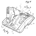
- the heating device according to the invention of Figures 1 to 3 is shown in use with alpine ski boots, it is of course not limited to such an application and can be designed and used with any other type of shoe having a rigid external upper, not necessarily in plastic material and can be for example very thick and rigid leather for a shoe walking / hiking, and a comfort interior lining, fixed or removable, at least partially thermoformable.
- the heating device 1 appears externally as a sort of fairly flat box with a substantially rectangular shape intended to be placed flat by its underside 1b on a horizontal surface.
- This device has on its upper face 1a two elongated and curved depressions 2, and each intended to constitute a reception and support seat for a shoe 11.
- each shoe is designed so as to provide stable support for the shoe placed upside down, heel up, the shoe being in fact supported on the seat 2 by its upper 12, ie its upper part of the foot / instep.
- the profile of seat 2 corresponds to an average profile of the upper of the shoe in function sizes and possibly the shoe model. The important thing is to obtain stable support from the shoe in this inverted position.
- each seat 2 is also provided a depression 3 of substantially shaped rectangular intended to receive and serve as housing for each of the heating nozzles 4, in outside periods of use and for transport.
- Each heating nozzle 4 is formed by a slightly curved tube at its end free 4a to adapt to the internal shape of the shoe.
- the curve of this tube can be modified according to the type of shoe to be thermoformed.
- each nozzle is provided over its entire length with fins or external peripheral grooves 5 intended to allow a more homogeneous diffusion outside of the hot air nozzle circulating outside of it, and also to avoid the risk of burns when gripping the nozzle, even when blowing hot air.
- These nozzles 4 may have a circular or rectangular section.
- each nozzle is closed at its free end 4a, but is provided near this end with at least two openings 6, diametrically opposite.
- openings can be arranged so as to be located opposite the heel and neck parts foot 13 of the lining of the shoe made of thermoformable material. They can also be arranged at 90 ° to the arrangement shown so as to heat more particularly the lateral zones, corresponding to the malleoli of the foot, of the shoe also made of thermoformable material.
- closing the nozzle 4 at its free end 4a is particularly important for avoid deterioration of the outer sole part 15 of the lining by hot air, in particular when it is not made of thermoformable material or when the shoe is slipped too far on the nozzle 4.
- the nozzle would be shaped so as to send hot air evenly over the surface of this soleplate internal.
- Another opening 7 is also provided on each nozzle so as to be opposite the tongue part 14 of the lining of the shoe.
- This air circulation is represented by the arrows 20.
- each nozzle is connected at its other end 4b to a supply pipe 8 in hot air.
- each nozzle has at its upper part a half cone 10 intended to cooperate with the upper end 16 of the shoe to limit the penetration of said nozzle inside the shoe.
- This half cone 10 is in the example shown consisting of a series of three half discs 10a each corresponding to the upper half-opening of a shoe according to extreme sizes and medians.
- the smallest disc 10a corresponds to a small size and the largest disc corresponds to a larger size.
- the cone 10 could be produced in another way, it could also be replaced by other abutment means constituted for example by a rod of adjustable length, not shown in the drawing, at the free end 4a of the nozzle and cooperating with the bottom 15 of the shoe for maintain the desired spacing between this and the nozzle 4.
- the cone 10 also has the additional advantage of closing the half-opening. upper of the shoe, i.e. the opening part of the shoe arranged between the rear of this shoe and the nozzle, and therefore prevent hot air from escaping through this opening.
- the hot air can only come out from under the nozzle 4 and it creates a sense of privileged air circulation, represented by arrows 20, in the heel / instep area, malleoli of the shoe and along the tongue 14 of the shoe.
- Such a construction therefore optimizes the use of hot air and the speed and quality of heating.
- the cone 10 also participates in maintaining each shoe on its seat 2 and in correct positioning of the nozzle inside thereof, adapting to the contour of the half-opening back of the shoe.
- Figure 2 shows the optimal positioning of the nozzle inside a shoe, know relatively centered with respect to the inner lining thereof.
- a stop elastic such as a leaf / spring (not shown in the drawing)
- a stop elastic could be provided on the part bottom of the nozzle, that is to say opposite the cone 10, to cooperate with the neck part of foot / tongue of the seal and perfectly guarantee the desired positioning of the nozzle,
- FIG. 3 shows more particularly the supply of hot air to each nozzle 4.
- This supply occurs from a hot air source 18, of a type known per se and not described more before, and producing hot air at a temperature between 120 ° and 140 °, and preferably at 130 ° C.
- This hot air is channeled through a pipe 17 which is connected to the supply pipe 8 of the nozzles 4.
- a switch 21 placed on the upper face 1a of the device allows setting heater on / off.
- Each of the nozzles 4 is mounted directly on the tubing and communicates with the interior thereof by an opening 8a.
- each nozzle 4 is mounted with a possibility of relative pivoting on the tubing 8, stops 19 formed on the upper part of the heating device limiting the pivoting angle of these nozzles.
- This pivoting in fact allows a certain movement of the nozzles in order to facilitate their positioning. in place inside each shoe, and their adaptation to different sizes.
- thermoforming of shoe lining not limited to a lining removable interior, such as the methods known up to now and can therefore be used for thermoforming fixed interior linings.
- thermoforming of the perimeter zone heel / instep and tongue of an interior trim which are the preferred areas of thermoforming. It could obviously be adapted to other areas of thermoforming.
Landscapes
- Engineering & Computer Science (AREA)
- Mechanical Engineering (AREA)
- Health & Medical Sciences (AREA)
- Epidemiology (AREA)
- General Health & Medical Sciences (AREA)
- Public Health (AREA)
- Footwear And Its Accessory, Manufacturing Method And Apparatuses (AREA)
- Liquid Crystal (AREA)
- Resistance Heating (AREA)
- Heating, Cooling, Or Curing Plastics Or The Like In General (AREA)
Claims (19)
- Verfahren für eine Thermo-Formung zumindest eines Teils einer Innen-Ausfütterung eines Schuhs, der einen steifen äußeren Schaft aufweist, dadurch gekennzeichnet, daß es aufweist:Leiten von heißer Luft bei einer Temperatur zwischen 120° und 140° mittels zumindest eines Ausgangs (6, 7) auf zumindest den Teil (13, 14) einer Ausfütterung, der im Inneren des Schuhs angeordnet ist,wobei gleichzeitig ein minimaler vorbestimmter Abstand zwischen jedem Ausgang (6, 7) von Heißluft und dem Teil (13, 14) der Ausfütterung garantiert wird.
- Verfahren nach Anspruch 1, dadurch gekennzeichnet, daß es darin besteht, den Schuh flach und umgekehrt im Verhältnis zum System (4) für eine Verteilung von Heißluft anzuordnen, derart, daß die Wärme im Inneren des Schuhs zurückgehalten bleibt.
- Vorrichtung für eine Thermo-Formung für das Durchführen des Verfahrens gemäß einem der Ansprüche 1 oder 2, dadurch gekennzeichnet, daß sie aufweist:zumindest eine Düse (4) für eine Verteilung von Heißluft, die angepaßt ist, ins Innere jedes Schuhs (1), der mit seiner Innen-Ausfütterung versehen ist, eingeführt zu werden,Positioniermittel der Düse im Inneren des Schuhs, welche einen vorbestimmten minimalen Abstand zwischen dem Ausgang der Düse für-Heißluft und der Innen-Ausfütterung garantieren.
- Vorrichtung für ein Thermo-Formen gemäß Anspruch 3, dadurch gekennzeichnet, daß die Positioniermittel jeder Düse im Inneren jedes Schuhs durch einen Sitz (2) gebildet sind, der geeignet ist, das Oberteil des Schuhs aufzunehmen.
- Vorrichtung für ein Thermo-Formen gemäß Anspruch 4, dadurch gekennzeichnet, daß jeder Sitz (2) ein Profil aufweist, das dem mittleren Profil des Oberteils (12) des Schuhs entsprechend den verschiedenen Größen entspricht.
- Vorrichtung für eine Thermo-Formung gemäß einem der Ansprüche 3 oder 4, dadurch gekennzeichnet, daß die Positioniermittel jeder Düse im Inneren jedes Schuhs einen Anschlag (10) aufweisen, der das Einführen derselben ins Innere des Schuhs begrenzt.
- Vorrichtung für eine Thermo-Formung gemäß Anspruch 6, dadurch gekennzeichnet, daß der Anschlag (10) in Abhängigkeit der Größen einstellbar ist.
- Vorrichtung für eine Thermo-Formung gemäß einem der Ansprüche 6 oder 7, dadurch gekennzeichnet, daß der Anschlag am freien Ende (4a) der Düse angeordnet ist und mit dem Boden (15) des Inneren des Schuhs zusammenwirkt.
- Vorrichtung für eine Thermo-Formung gemäß einem der Ansprüche 6 oder 7, dadurch gekennzeichnet, daß der Anschlag (10) mit dem oberen Ende (16) des Schuhs zusammenwirkt.
- Vorrichtung für eine Thermo-Formung gemäß irgendeinem der Ansprüche 3 bis 9, dadurch gekennzeichnet, daß die Düse (4) eine leicht ausgebauchte Form aufweist.
- Vorrichtung für eine Thermo-Formung gemäß irgendeinem der Ansprüche 3 bis 10, dadurch gekennzeichnet, daß die Düse (4) mit einem Ende (4b) mit einer Heißluftquelle (18) verbunden ist und schwenkbar auf Höhe dieses Endes montiert ist.
- Vorrichtung für eine Thermo-Formung gemäß irgendeinem der Ansprüche 3 bis 11, dadurch gekennzeichnet, daß die Düse (4) an ihrem freien Ende (4a) geschlossen ist und zurückspringend von diesem Ende zumindest zwei Öffnungen (6) für einen Durchgang von Heißluft aufweist, die diametral gegenüberliegend sind.
- Vorrichtung für eine Thermo-Formung gemäß Anspruch 12, dadurch gekennzeichnet, daß die Düse (4) zumindest eine dritte Heizöffnung (7) aufweist, die der Zunge der Ausfütterung gegenüberliegend angeordnet ist.
- Vorrichtung für eine Thermo-Formung gemäß irgendeinem der Ansprüche 3 bis 13, dadurch gekennzeichnet, daß die Düse (4) mit Rillen (5) über ihre gesamte Länge versehen ist.
- Vorrichtung für eine Thermo-Formung gemäß irgendeinem der Ansprüche 3 bis 14, dadurch gekennzeichnet, daß die Düse (4) Mittel (10) für ein Verschließen der Öffnung des Schaftes des Schuhs zwischen dieser Düse (4) und dem hinteren Teil des Schaftes aufweist.
- Vorrichtung für eine Thermo-Formung gemäß den Ansprüchen 15 und 9, dadurch gekennzeichnet, daß die Mittel für ein Verschließen durch den Anschlag (10) gebildet sind.
- Ausfütterung in Kombination mit der Vorrichtung gemäß einem der Ansprüche 3 bis 16, dadurch gekennzeichnet, daß die Ausfütterung ein thermo-formbares Material über die gesamte perimetrische Absatz/Fußhals-Zone 13 und über die Zunge (14) aufweist.
- Ausfütterung und Vorrichtung gemäß Anspruch 17, dadurch gekennzeichnet, daß die Ausfütterung abnehmbar ist.
- Ausfütterung und Vorrichtung gemäß Anspruch 17, dadurch gekennzeichnet, daß die Ausfütterung im Innern des Schuhs befestigt ist.
Applications Claiming Priority (3)
| Application Number | Priority Date | Filing Date | Title |
|---|---|---|---|
| FR9512120 | 1995-10-11 | ||
| FR9512120A FR2739760B1 (fr) | 1995-10-11 | 1995-10-11 | Procede et dispositif de chauffage d'une garniture interieure de chaussure |
| PCT/FR1996/001480 WO1997013447A1 (fr) | 1995-10-11 | 1996-09-23 | Procede et dispositif de chauffage d'une garniture interieure de chaussure |
Publications (3)
| Publication Number | Publication Date |
|---|---|
| EP0802764A1 EP0802764A1 (de) | 1997-10-29 |
| EP0802764B1 true EP0802764B1 (de) | 2001-06-27 |
| EP0802764B2 EP0802764B2 (de) | 2004-03-17 |
Family
ID=9483573
Family Applications (1)
| Application Number | Title | Priority Date | Filing Date |
|---|---|---|---|
| EP96932634A Expired - Lifetime EP0802764B2 (de) | 1995-10-11 | 1996-09-23 | Vorrichtung und verfahren zum wärmen einer fütterung für schuhwerk |
Country Status (9)
| Country | Link |
|---|---|
| US (1) | US5894680A (de) |
| EP (1) | EP0802764B2 (de) |
| JP (1) | JPH10511031A (de) |
| AT (1) | ATE202462T1 (de) |
| AU (1) | AU716448B2 (de) |
| CA (1) | CA2208434A1 (de) |
| DE (1) | DE69613559T3 (de) |
| FR (1) | FR2739760B1 (de) |
| WO (1) | WO1997013447A1 (de) |
Families Citing this family (25)
| Publication number | Priority date | Publication date | Assignee | Title |
|---|---|---|---|---|
| CH693584A5 (fr) | 1999-12-21 | 2003-10-31 | Lange Int Sa | Chausson de confort pour chaussure de sport. |
| US6216359B1 (en) * | 2000-01-14 | 2001-04-17 | Peet Shoe Dryer, Inc. | Gas fired garment dryer |
| DE20001932U1 (de) | 2000-01-31 | 2000-04-20 | Macher & Zorn Oeg, Grambach | Vorrichtung zum Trocknen von Schuhen, Handschuhen oder textilen Kleidungsstücken |
| US6766591B1 (en) | 2003-05-07 | 2004-07-27 | Hp Intellectual Corp. | Garment drying apparatus |
| US8467876B2 (en) * | 2003-10-15 | 2013-06-18 | Rmx, Llc | Breathing disorder detection and therapy delivery device and method |
| DE10358042B3 (de) * | 2003-12-05 | 2005-06-30 | Therm-Ic Products Gmbh | Vorrichtung zum Trocknen von Schuhen, Handschuhen, Kleidungsstücken oder dergleichen |
| US7526876B2 (en) * | 2005-01-27 | 2009-05-05 | Seirus Innovative Accessories, Inc. | Multiuse dryer and method of drying multiple items |
| FR2903174B1 (fr) | 2006-06-28 | 2015-07-24 | Salomon Sa | Chaussure a coque rigide |
| FR2902981B1 (fr) | 2006-06-28 | 2008-10-31 | Salomon Sa | Chaussure a coque rigide |
| US7716849B1 (en) * | 2006-07-12 | 2010-05-18 | Neil Hicks | Glove dryer |
| US8984766B2 (en) * | 2009-08-19 | 2015-03-24 | Williams Boot & Glove Dryers Inc. | Boot and glove dryer for food service industry and method of making same |
| US9221211B2 (en) * | 2011-11-28 | 2015-12-29 | Greg Klein | Heat/vacuum molding system for footwear |
| US20150230539A1 (en) | 2014-02-17 | 2015-08-20 | Calzaturificio Dal Bello S.R.L. | Sport Footwear for Practicing Winter Sports and Corresponding Method of Production |
| US10143354B2 (en) * | 2016-05-19 | 2018-12-04 | Iron Lake LLC | Ducted footwear dryer |
| US10266985B2 (en) * | 2016-06-03 | 2019-04-23 | Samsung Electronics Co., Ltd. | Collapsible drying rack for laundry dryer |
| USRE50689E1 (en) | 2016-06-28 | 2025-12-09 | Lawrence A. Hinkey | Portable apparel drying assemblies and methods of use |
| US10718565B2 (en) | 2016-06-28 | 2020-07-21 | Lawrence A. Hinkey | Methods of drying apparel and apparel drying assemblies |
| US10197332B2 (en) * | 2016-06-28 | 2019-02-05 | Lawrence A. Hinkey | Apparel drying assemblies and methods of drying apparel |
| US10961655B2 (en) | 2016-06-28 | 2021-03-30 | Lawrence A. Hinkey | Portable apparel drying assemblies and methods of use |
| US10238268B2 (en) * | 2016-09-20 | 2019-03-26 | Kairat Nurlybekov | Shoe dryer |
| USD872393S1 (en) * | 2017-03-15 | 2020-01-07 | Xiaoping Xiao | Shoe dryer |
| US12465111B2 (en) * | 2020-02-14 | 2025-11-11 | Bauer Hockey Llc | Skate or other footwear |
| FR3116700B1 (fr) | 2020-11-30 | 2023-10-13 | Rossignol Lange Srl | Dispositif de thermoformage des chaussures de ski |
| USD995959S1 (en) | 2021-04-28 | 2023-08-15 | Upper Echelon Products Llc | Boot dryer |
| USD967572S1 (en) * | 2021-09-28 | 2022-10-18 | Chunyu Zhang | Shoe dryer |
Family Cites Families (14)
| Publication number | Priority date | Publication date | Assignee | Title |
|---|---|---|---|---|
| US2446234A (en) * | 1945-10-09 | 1948-08-03 | Edward H Lieber | Boot drier |
| US3299529A (en) * | 1964-04-02 | 1967-01-24 | Hershel C Roberts | Drier device for ski shoes and the like |
| DE2623405A1 (de) * | 1976-05-25 | 1977-12-08 | Hans Woedl | Waerm- und trockenvorrichtung fuer schuhe |
| FR2406790A1 (fr) * | 1977-10-24 | 1979-05-18 | Blanc Roger | Appareil pour le sechage des chaussures |
| JPS602041B2 (ja) * | 1978-04-06 | 1985-01-18 | ランジ アンテルナシオナル ソシエテ アノニム | 身体の一部に着用する「はい」用物品およびその適合方法 |
| DE3421372A1 (de) * | 1984-06-08 | 1985-12-12 | Franz 7972 Isny Eggensberger | Trockner fuer schuhe und insbesondere stiefel mit langen schaeften |
| IT1207746B (it) * | 1987-02-25 | 1989-06-01 | Antonio Rossi | Dispositivo di riscaldamento e di sterilizzazione in particolare per scarponi da sci. |
| US4768293A (en) † | 1987-05-11 | 1988-09-06 | Kaffka Michael G | Footwear drying apparatus |
| US4787153A (en) * | 1987-12-30 | 1988-11-29 | Yi Chen | Shoe drier |
| JPH0246896A (ja) * | 1988-08-09 | 1990-02-16 | Matsushita Electric Ind Co Ltd | 衣類乾燥機 |
| JPH0246876A (ja) * | 1988-08-09 | 1990-02-16 | Yamaha Corp | インナーブーツ加熱装置 |
| US5085289A (en) * | 1988-09-09 | 1992-02-04 | Chance John H | Shock-absorbing resilient coupling |
| US4964229A (en) * | 1989-02-03 | 1990-10-23 | Sport Maska, Inc. | Method and apparatus for vacuum molding multi-layer footwear |
| DE29502189U1 (de) * | 1995-02-10 | 1995-04-13 | Tseng, James, Taipeh/T'ai-pei | Trocknungs- und Desodorierungsvorrichtung für Schuhe |
-
1995
- 1995-10-11 FR FR9512120A patent/FR2739760B1/fr not_active Expired - Fee Related
-
1996
- 1996-09-23 JP JP9514753A patent/JPH10511031A/ja active Pending
- 1996-09-23 DE DE69613559T patent/DE69613559T3/de not_active Expired - Lifetime
- 1996-09-23 AT AT96932634T patent/ATE202462T1/de active
- 1996-09-23 EP EP96932634A patent/EP0802764B2/de not_active Expired - Lifetime
- 1996-09-23 WO PCT/FR1996/001480 patent/WO1997013447A1/fr not_active Ceased
- 1996-09-23 AU AU71341/96A patent/AU716448B2/en not_active Ceased
- 1996-09-23 CA CA002208434A patent/CA2208434A1/fr not_active Abandoned
- 1996-09-23 US US08/849,083 patent/US5894680A/en not_active Expired - Lifetime
Also Published As
| Publication number | Publication date |
|---|---|
| US5894680A (en) | 1999-04-20 |
| WO1997013447A1 (fr) | 1997-04-17 |
| AU7134196A (en) | 1997-04-30 |
| FR2739760B1 (fr) | 1997-12-12 |
| DE69613559T3 (de) | 2004-09-16 |
| ATE202462T1 (de) | 2001-07-15 |
| DE69613559T2 (de) | 2002-04-18 |
| DE69613559D1 (de) | 2001-08-02 |
| FR2739760A1 (fr) | 1997-04-18 |
| EP0802764A1 (de) | 1997-10-29 |
| EP0802764B2 (de) | 2004-03-17 |
| JPH10511031A (ja) | 1998-10-27 |
| AU716448B2 (en) | 2000-02-24 |
| CA2208434A1 (fr) | 1997-04-17 |
Similar Documents
| Publication | Publication Date | Title |
|---|---|---|
| EP0802764B1 (de) | Vorrichtung und verfahren zum wärmen einer fütterung für schuhwerk | |
| EP0004829B1 (de) | Verfahren zum Anpassen eines Bekleidungselementes oder Zubehörs an einen Teil des menschlichen Körpers und Element oder Zubehör zur Durchführung des Verfahrens | |
| EP0790788B1 (de) | Innenbekleidung fuer schuhe | |
| EP1872678B1 (de) | Schuh mit starrer Schale | |
| EP1166667A1 (de) | Innenschuh für Schischuh | |
| EP1428444A1 (de) | Kletterschuh | |
| FR2512331A1 (fr) | Chaussure a talon fixe de facon amovible | |
| EP3020300B1 (de) | Innenschuh für Sportschuh | |
| FR2849994A1 (fr) | Semelle interne | |
| EP2674049A1 (de) | Innenschuh für Sportschuh | |
| EP0702907B1 (de) | Innenschuh für Schischuh | |
| EP1415558B1 (de) | Komfortartikel für einen Sportschuh | |
| EP4088609B1 (de) | Abnehmbare zunge für skischuh-innenschuh | |
| EP4085783B1 (de) | Thermoformbarer schuh mit haltefolie | |
| FR3116700A1 (fr) | Dispositif de thermoformage des chaussures de ski | |
| FR2782613A1 (fr) | Module pour la realisation par thermoformage d'ortheses podologiques, installation pour la mise en oeuvre d'un tel module et procede pour la realisation d'ortheses podologiques | |
| FR2635651A1 (fr) | Poche d'injection pour l'obtention d'une semelle interne a une chaussure a coque rigide, procede pour l'obtention d'une telle semelle, et semelle ainsi obtenue | |
| FR2548876A1 (fr) | Article chaussant a talon, en matiere plastique | |
| FR2628300A1 (fr) | Procede de fabrication d'un article chaussant de type mocassin, dont la semelle evidee comporte un insert | |
| WO2023057357A1 (fr) | Piece de maintien de cheville pour chausson ou chaussure | |
| FR2903174A1 (fr) | Chaussure a coque rigide | |
| FR3066887A1 (fr) | Dispositif de chauffage pour chaussures de sport | |
| CH689438A5 (fr) | Chausson de confort pour chaussures de ski. |
Legal Events
| Date | Code | Title | Description |
|---|---|---|---|
| PUAI | Public reference made under article 153(3) epc to a published international application that has entered the european phase |
Free format text: ORIGINAL CODE: 0009012 |
|
| 17P | Request for examination filed |
Effective date: 19970514 |
|
| AK | Designated contracting states |
Kind code of ref document: A1 Designated state(s): AT CH DE FR IT LI |
|
| 17Q | First examination report despatched |
Effective date: 19990302 |
|
| GRAG | Despatch of communication of intention to grant |
Free format text: ORIGINAL CODE: EPIDOS AGRA |
|
| GRAG | Despatch of communication of intention to grant |
Free format text: ORIGINAL CODE: EPIDOS AGRA |
|
| GRAH | Despatch of communication of intention to grant a patent |
Free format text: ORIGINAL CODE: EPIDOS IGRA |
|
| GRAH | Despatch of communication of intention to grant a patent |
Free format text: ORIGINAL CODE: EPIDOS IGRA |
|
| GRAA | (expected) grant |
Free format text: ORIGINAL CODE: 0009210 |
|
| AK | Designated contracting states |
Kind code of ref document: B1 Designated state(s): AT CH DE FR IT LI |
|
| REF | Corresponds to: |
Ref document number: 202462 Country of ref document: AT Date of ref document: 20010715 Kind code of ref document: T |
|
| REG | Reference to a national code |
Ref country code: CH Ref legal event code: EP |
|
| ITF | It: translation for a ep patent filed | ||
| REF | Corresponds to: |
Ref document number: 69613559 Country of ref document: DE Date of ref document: 20010802 |
|
| PLBI | Opposition filed |
Free format text: ORIGINAL CODE: 0009260 |
|
| PLBQ | Unpublished change to opponent data |
Free format text: ORIGINAL CODE: EPIDOS OPPO |
|
| PLBF | Reply of patent proprietor to notice(s) of opposition |
Free format text: ORIGINAL CODE: EPIDOS OBSO |
|
| 26 | Opposition filed |
Opponent name: THERM-IC PRODUCTS GMBH Effective date: 20020326 |
|
| PLBF | Reply of patent proprietor to notice(s) of opposition |
Free format text: ORIGINAL CODE: EPIDOS OBSO |
|
| PUAH | Patent maintained in amended form |
Free format text: ORIGINAL CODE: 0009272 |
|
| STAA | Information on the status of an ep patent application or granted ep patent |
Free format text: STATUS: PATENT MAINTAINED AS AMENDED |
|
| 27A | Patent maintained in amended form |
Effective date: 20040317 |
|
| AK | Designated contracting states |
Kind code of ref document: B2 Designated state(s): AT CH DE FR IT LI |
|
| REG | Reference to a national code |
Ref country code: CH Ref legal event code: AEN Free format text: MAINTIEN DU BREVET DONT L'ETENDUE A ETE MODIFIEE |
|
| REG | Reference to a national code |
Ref country code: CH Ref legal event code: PFA Owner name: SALOMON S.A.S. Free format text: SALOMON S.A.#LA RAVOIRE#74370 METZ-TESSY (FR) -TRANSFER TO- SALOMON S.A.S.#LES CROISELETS#74370 METZ-TESSY (FR) |
|
| REG | Reference to a national code |
Ref country code: FR Ref legal event code: CJ Ref country code: FR Ref legal event code: CA |
|
| PGFP | Annual fee paid to national office [announced via postgrant information from national office to epo] |
Ref country code: CH Payment date: 20110913 Year of fee payment: 16 |
|
| PGFP | Annual fee paid to national office [announced via postgrant information from national office to epo] |
Ref country code: IT Payment date: 20110913 Year of fee payment: 16 |
|
| PGFP | Annual fee paid to national office [announced via postgrant information from national office to epo] |
Ref country code: AT Payment date: 20120829 Year of fee payment: 17 |
|
| PG25 | Lapsed in a contracting state [announced via postgrant information from national office to epo] |
Ref country code: IT Free format text: LAPSE BECAUSE OF NON-PAYMENT OF DUE FEES Effective date: 20120923 |
|
| PGFP | Annual fee paid to national office [announced via postgrant information from national office to epo] |
Ref country code: DE Payment date: 20130918 Year of fee payment: 18 |
|
| PGFP | Annual fee paid to national office [announced via postgrant information from national office to epo] |
Ref country code: FR Payment date: 20130910 Year of fee payment: 18 |
|
| REG | Reference to a national code |
Ref country code: CH Ref legal event code: PL |
|
| REG | Reference to a national code |
Ref country code: AT Ref legal event code: MM01 Ref document number: 202462 Country of ref document: AT Kind code of ref document: T Effective date: 20130923 |
|
| PG25 | Lapsed in a contracting state [announced via postgrant information from national office to epo] |
Ref country code: LI Free format text: LAPSE BECAUSE OF NON-PAYMENT OF DUE FEES Effective date: 20130930 Ref country code: CH Free format text: LAPSE BECAUSE OF NON-PAYMENT OF DUE FEES Effective date: 20130930 |
|
| PG25 | Lapsed in a contracting state [announced via postgrant information from national office to epo] |
Ref country code: AT Free format text: LAPSE BECAUSE OF NON-PAYMENT OF DUE FEES Effective date: 20130923 |
|
| REG | Reference to a national code |
Ref country code: DE Ref legal event code: R119 Ref document number: 69613559 Country of ref document: DE |
|
| REG | Reference to a national code |
Ref country code: DE Ref legal event code: R119 Ref document number: 69613559 Country of ref document: DE Effective date: 20150401 |
|
| REG | Reference to a national code |
Ref country code: FR Ref legal event code: ST Effective date: 20150529 |
|
| PG25 | Lapsed in a contracting state [announced via postgrant information from national office to epo] |
Ref country code: DE Free format text: LAPSE BECAUSE OF NON-PAYMENT OF DUE FEES Effective date: 20150401 |
|
| PG25 | Lapsed in a contracting state [announced via postgrant information from national office to epo] |
Ref country code: FR Free format text: LAPSE BECAUSE OF NON-PAYMENT OF DUE FEES Effective date: 20140930 |