EP0803180A1 - Dispositif d'entrainement pour machine autotractee - Google Patents
Dispositif d'entrainement pour machine autotractee Download PDFInfo
- Publication number
- EP0803180A1 EP0803180A1 EP96929549A EP96929549A EP0803180A1 EP 0803180 A1 EP0803180 A1 EP 0803180A1 EP 96929549 A EP96929549 A EP 96929549A EP 96929549 A EP96929549 A EP 96929549A EP 0803180 A1 EP0803180 A1 EP 0803180A1
- Authority
- EP
- European Patent Office
- Prior art keywords
- transmission
- height regulating
- cutter housing
- rolling member
- prime mover
- Prior art date
- Legal status (The legal status is an assumption and is not a legal conclusion. Google has not performed a legal analysis and makes no representation as to the accuracy of the status listed.)
- Granted
Links
Images


Classifications
-
- A—HUMAN NECESSITIES
- A01—AGRICULTURE; FORESTRY; ANIMAL HUSBANDRY; HUNTING; TRAPPING; FISHING
- A01D—HARVESTING; MOWING
- A01D34/00—Mowers; Mowing apparatus of harvesters
- A01D34/01—Mowers; Mowing apparatus of harvesters characterised by features relating to the type of cutting apparatus
- A01D34/412—Mowers; Mowing apparatus of harvesters characterised by features relating to the type of cutting apparatus having rotating cutters
- A01D34/63—Mowers; Mowing apparatus of harvesters characterised by features relating to the type of cutting apparatus having rotating cutters having cutters rotating about a vertical axis
- A01D34/74—Cutting-height adjustment
-
- A—HUMAN NECESSITIES
- A01—AGRICULTURE; FORESTRY; ANIMAL HUSBANDRY; HUNTING; TRAPPING; FISHING
- A01D—HARVESTING; MOWING
- A01D34/00—Mowers; Mowing apparatus of harvesters
- A01D34/01—Mowers; Mowing apparatus of harvesters characterised by features relating to the type of cutting apparatus
- A01D34/412—Mowers; Mowing apparatus of harvesters characterised by features relating to the type of cutting apparatus having rotating cutters
- A01D34/63—Mowers; Mowing apparatus of harvesters characterised by features relating to the type of cutting apparatus having rotating cutters having cutters rotating about a vertical axis
- A01D34/67—Mowers; Mowing apparatus of harvesters characterised by features relating to the type of cutting apparatus having rotating cutters having cutters rotating about a vertical axis hand-guided by a walking operator
- A01D34/68—Mowers; Mowing apparatus of harvesters characterised by features relating to the type of cutting apparatus having rotating cutters having cutters rotating about a vertical axis hand-guided by a walking operator with motor driven cutters or wheels
- A01D34/69—Mowers; Mowing apparatus of harvesters characterised by features relating to the type of cutting apparatus having rotating cutters having cutters rotating about a vertical axis hand-guided by a walking operator with motor driven cutters or wheels with motor driven wheels
-
- A—HUMAN NECESSITIES
- A01—AGRICULTURE; FORESTRY; ANIMAL HUSBANDRY; HUNTING; TRAPPING; FISHING
- A01D—HARVESTING; MOWING
- A01D2101/00—Lawn-mowers
Definitions
- the present invention relates to an improvement in a system for driving a walking-type working machine such as a walking-type lawn mower, the system including a height regulating device.
- a transmission 08 having a clutch operatively associated with a prime mover is mounted on a rear portion of a cutter housing H', and a rear roller R' is disposed at a distance from the rear of the transmission 08.
- the transmission 08 and the rear roller R' are interconnected through an endless transmitting mechanism, so that the rear roller R' is rotated by the prime mover through the transmission 08.
- the rear roller R' is carried at a rear end of a height regulating arm 23 which is swingably supported coaxially with a transmission output shaft 012 of the transmission 08, so that the lifting and lowering of the rear roller R' are controlled by regulating the swinging movement of the height regulating arm 023.
- the system for driving such conventional walking-type working machine suffers from the following problems:
- the present invention has been accomplished with such circumstance in view, and accordingly, it is an object of the present invention to provide a novel system for driving a walking-type working machine, wherein the above-described problems can be solved.
- a system for driving a walking-type working machine comprising a prime mover mounted on a cutter housing, so that a cutter is driven by the prime mover, and a rear rolling member is also driven by the prime mover through a transmission, characterized in that the transmission is supported on a rear portion of the cutter housing, and the rear rolling member is suspended below the transmission for regulatable lifting and lowering movements, the transmission having a transmission output shaft operatively connected to the rear rolling member through a transmitting mechanism.
- the cutter housing With the first feature of the present invention, it is possible to reduce the size and weight of the cutter housing to provide an inexpensive driving system. In addition, it is possible to provide a small sharp turn to considerably increase the working area, and further to reduce the rear rolling member pushing-up load.
- a system for driving a walking-type working machine comprising a prime mover mounted on a cutter housing, so that a cutter is driven by the prime mover, and a rear rolling member is also driven by the prime mover through a transmission, characterized in that the system further includes a height regulating shaft provided on the cutter housing at a distance spaced apart from the transmission, and a height regulating arm swingably supported on the height regulating shaft, the rear rolling member disposed below the transmission being rotatably carried on the height regulating arm, so that the rear rolling member can be lifted and lowered by controlling the swinging movement of the height regulating arm.
- the second feature of the present invention it is possible to reduce the size and weight of the cutter housing to provide an inexpensive driving system. In addition, it is possible to provide a small sharp turn to considerably increase the working area, and further to reduce the rear rolling member pushing-up load. Moreover, it is possible to enhance the freedom degree of disposition of the transmission on the cutter housing.
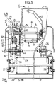
- the walking-type lawn mower includes a cutter housing H with its lower surface opened.
- a pair of left and right front wheels Wf, Wf are suspended laterally in a front portion of the cutter housing H.
- the front wheels Wf, Wf are liftable and lowerable in a regulatable manner with respect to the cutter housing H by a conventionally known height regulating mechanism.
- a prime mover i.e., a vertical-type engine E is mounted on the cutter housing H and has a vertical output shaft 6 which extends vertically within the cutter housing H, and a lawn mowing cutter C is connected to the vertical-type engine E.
- Supporting structures for the engine E, the cutter C and the cutter housing H are conventionally known and hence, the detailed description of them is omitted.
- a handle post Ph for operating the lawn mower is mounted to the rear portion of the cutter housing H to extend obliquely upwards, and a steering device for steering the lawn mower is mounted on the handle post Ph.
- Reference character K is a key switch
- reference character Z is a recoiled starter.
- a substantially flat rear deck surface 1 is formed on the rear portion of the cutter housing H and inclined downwards from a position above the rear roller R in a rearward direction.
- a lawn releasing outlet 3 of a lawn releasing passage 2 defined in the cutter housing H opens into laterally one side (a right side in an advancing direction of the lawn mower) of the rear deck surface 1, so that lawn cut-down by the cutter C is passed through the lawn release passage 2 and released from the lawn release outlet 3, as usual.
- a battery mounting surface for detachably mounting a battery serving as a power source for an electric device such as starter motor of the engine E is formed on the other side (a left side in the advancing direction of the lawn mower) of the rear deck surface 1 in parallel to the lawn release outlet 3.
- a grass bag 4 is upward-openably and closably and detachably mounted to the rear deck surface 1 to cover the lawn release outlet 3, so that the lawn released from the lawn release outlet 3 is accommodated into the grass bag 4.
- a rear discharger cover 5 is vertically openably and closably carried on an upper edge of the rear portion of the cutter housing H to hold an upper surface of a front portion of the grass bag 4. The rear discharger cover 5 is used as a lawn guide/release passage by rotating it to a closed position and retaining it at the closed position after removing the grass bag 4.
- the rear roller R can be rotated by the driving system (which will be described hereinafter) including the engine E, and lifted and lowered with respect to the cutter housing H by the height regulating mechanism which will be described hereinafter, thereby regulating the height of the cutter C to regulate the lawn mowing height.
- the driving system which will be described hereinafter
- the height regulating mechanism which will be described hereinafter
- a driving pulley 7 is secured to the output shaft 6 of the engine E, while a driven pulley 10 is secured to a transmission input shaft 9 which depends downward from a transmission 8 supported in the rear portion of the cutter housing H.
- a transmitting belt 11 extending substantially horizontally is reeved around the pulleys 7 and 10.
- the driving pulley 7, the driven pulley 10 and the transmitting belt 11 constitute a belt transmitting mechanism 16 and thus, a driving power from the engine E is transmitted through the belt transmitting mechanism 16 to the transmission input shaft 9 of the transmission 8.
- the transmission 8 is disposed in a dead space defined in the rear portion of the cutter housing H, and the transmission input shaft 9, which contains a cone clutch therein and connected to the engine E, depends vertically.
- the transmission input shaft 9 is oil-tightly sealed to a mission case 8 1 by a seal means and thus constructed so that a lubricating oil or the like is prevented from being leaked, even if the transmission input shaft 9 depends downwards from the transmission case 8 1 .
- the transmission 8 is supported in the cutter housing H above the rear roller R in a manner which will described in detail hereinafter.
- the own weight of transmission 8 acts on the rear roller R to increase the driving force of the rear roller R.
- a transmission output shaft 12 extending laterally from the transmission case 8 1 is rotatably supported integrally at its inner end on a transmission holder 13 integrally supported to the cutter housing H in a hung manner through a ball bearing 14.
- the transmission output shaft 12 is also rotatably supported at its outer end through a ball bearing 15 in a height regulating panel 17 fixed to the cutter housing 1.
- the transmission case 8 1 of the transmission 8 is resiliently supported at its one side (rear side)on a bracket 18 integral with the cutter housing H with a support spring comprised of a compression coil spring interposed therebetween.
- the transmission 8 is resiliently supported on the cutter housing H for vertically swinging movement about the transmission output shaft 12, so that a resilient force of the support spring 19 biases the transmission 8 to swing it upwards as shown by an arrow a in Fig.6, thereby applying a tension of the transmitting belt 11.
- an outer end of the mission output shaft 12 of the transmission 8 protrudes through a sidewall surface of the cutter housing H to the outside of such sidewall surface, and a driving sprocket 21 is secured to a free end of the transmission output shaft 12 and operatively associated with the rear roller R.
- a height regulating shaft 22 is secured to one (a left sidewall surface in the advancing direction of the lawn mower) of sidewall surfaces of the cutter housing H substantially in parallel to the mission output shaft 12.
- the height regulating shaft 22 is extended outwards from the cutter housing H in the same direction, as is the transmission output shaft 12, and a height regulating arm 23 formed into a bell crank-like shape is vertically swingably supported at its intermediate portion on an outer end of the height regulating shaft 22, as shown in Figs.7 and 8.
- a support shaft 24 is secured to the other sidewall surface (at a right side in the advancing direction of the lawn mower) on the same axis L-L as the height regulating shaft 22, and a swingable arm 25 bent into a crank-like shape is vertically swingably supported on the support shaft 24.
- a lower arm portion 23 2 of the bell crank-like height regulating arm 23 and a lower end of the swingable arm 25 are integrally interconnected by a connecting rod 26, so that they are swung synchronously about the height regulating shaft 22.
- the rear roller R is rotatably supported between the lower arm portion 23 2 of the height regulating arm 23 and a lower end of the swingable arm 25 with ball bearings 27 and 28 interposed therebetween.
- the rear roller R is comprised of a roller shaft 30 secured in a penetrating manner in a central portion of a tightly-closed hollow roller body 29, as shown in Fig.5.
- the lifting and lowering of the rear roller R can be regulated with respect to the cutter housing H by the vertically swinging movements of the height regulating arm 23 and the swingable arm 25, thereby regulating the height of the cutter C to regulate the lawn mowing height.
- a driven sprocket 31 corresponding to the driving sprocket 21 is secured to one end of the roller shaft 30 of the rear roller R, and an idle roller 32 is rotatably supported on the height regulating shaft 22.
- An endless transmitting chain 33 is reeved around the driving sprocket 21, the driven sprocket 31 and the idle roller 32.
- the driving sprocket 21, the driven sprocket 31 and the transmitting chain 33 constitute a chain transmitting mechanism 34, so that an output from the transmission 8 is transmitted through the chain transmitting mechanism 34 to the rear roller R.
- a tension roller 37 is disposed halfway between the driving sprocket 21 and the idle roller 32 outside the transmitting chain 33 and swingably supported on the height regulating shaft 22 with a tension arm 36 interposed therebetween.
- a tension spring 38 comprised of an extension spring is fastened at one end to an intermediate portion of the tension arm 36 and at the other end to a height regulating panel 17, so that the tension roller 37 can be brought into pressure contact with the transmitting chain 33 from the outside of the latter by a resilient force of the tension spring 38 to regulate the tension of the transmitting chain 33 to a constant level.
- a height regulating lever 40 formed of a resilient plate is secured to the height regulating shaft 22.
- the height regulating lever 40 extends upwards along an upper arm portion 23 1 of the height regulating arm 23, and a handle 41 is secured to an upper end of the height regulating lever 40.
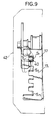
- a handle locking portion 17 1 is integrally formed arcuately about the height regulating shaft 22 on an upper portion of height regulating panel 17, and a plurality of locking recesses S 1 - S n are provided in a row in the handle locking portion 17 1 , as clearly shown in Fig.9, so that the height regulating lever 40 can be selectively locked in one of the locking recesses S 1 - S n .
- the lawn mower is regulated to a highest position, and if the height regulating lever 40 is locked in the locking recess S 1 , as shown in Fig.8, the lawn mower is regulated to a lowest position.
- the height regulating panel 17, the height regulating shaft 22, the height regulating arm 23 and the height regulating lever 40 constitute a height regulating mechanism Ah of the lawn mower.
- reference character 42 is a cover which is supported on the cutter housing H to cover the height regulating mechanism Ah.
- the cutter C is rotated, and the transmission 8 having the cone clutch is driven through the belt transmitting mechanism 16. Further, the rear roller R is rotated through the chain transmitting mechanism 34, whereby the lawn mowing operation can be carried out by the cutter C, and the ground surface after being just subjected to the lawn-mowing can be rolled by the roller R.
- the regulation of the lawn mowing height is achieved by the regulation of the longitudinally swinging movement of the height regulating lever 40. For example, if the height regulating lever 40 is swung to a rearmost position, as shown in Fig.7, the height regulating arm 23 is swung downwards (in a direction d in Fig.7) about the height regulating shaft 17 along with the rear roller R to lift the cutter housing H. If the height regulating lever 40 is then locked into the lowermost locking recess S n , the cutter housing H is retained at the highest position. In this manner, the lawn mowing height of the cutter C can be regulated to a highest level.
- the height regulating level 40 is swung to a foremost position, as shown in Fig.8, the height regulating arm 23 is swung upwards (in a direction u in Fig.8) about the height regulating shaft 17 along with the rear roller R to lift the cutter housing H. If the height regulating lever 40 is then locked into the uppermost locking recess S 1 , the cutter housing H is retained at the lowest position. In this manner, the lawn mowing height of the cutter C can be regulated to a lowest level. Further, if the height regulating lever 40 is selectively locked into one of the middle locking recesses, the cutter housing H can be stepwise retained at the middle position.
- the height regulating lever 40 may be constructed so that its swinging movement can be continuously regulated, whereby the lifting and lowering of the cutter housing H may be continuously regulated.
- the size and weight of the cutter housing H can be reduced more than those in the conventional system, leading to a considerably reduced manufacture cost of the cutter housing H.
- the distance between the axles of the front wheels Wf, Wf and the roller shaft 30 of the rear roller R, i.e., a wheel base is reduced more than that in the prior art, leading to a decreased turning radius of the lawn mower, so that the working machine is capable of a smaller sharp turn, thereby considerably increasing the lawn mowing area.
- a sleep ground area i.e., an unmowed ground area
- the load of pushing by the height regulating lever 40 can be reduced.
- the degree of freedom in selecting the place for disposition of the transmission 8 can be increased.
- the transmission 8 is disposed above the rear roller R, the own weight of the transmission 8 can be caused to act on the rear roller R, thereby increasing the driving force of the rear roller R.
- the present invention is not limited to the above-described embodiment, and various modifications may be made within the spirit and scope of the present invention.
- the above-described embodiment has been described as being applied to the walking-type lawn mower, but the present invention is also applicable to another walking-type working machine.
- the rear roller may be used as a rear wheel.
- the lifting and lowering of the rear roller are regulated at stages in the embodiment, but may be regulated continuously.
Landscapes
- Life Sciences & Earth Sciences (AREA)
- Environmental Sciences (AREA)
- Harvester Elements (AREA)
Applications Claiming Priority (4)
| Application Number | Priority Date | Filing Date | Title |
|---|---|---|---|
| JP23361295A JP3195204B2 (ja) | 1995-09-12 | 1995-09-12 | 歩行作業機の駆動装置 |
| JP233612/95 | 1995-09-12 | ||
| JP23361295 | 1995-09-12 | ||
| PCT/JP1996/002544 WO1997009871A1 (fr) | 1995-09-12 | 1996-09-06 | Dispositif d'entrainement pour machine autotractee |
Publications (3)
| Publication Number | Publication Date |
|---|---|
| EP0803180A1 true EP0803180A1 (fr) | 1997-10-29 |
| EP0803180A4 EP0803180A4 (fr) | 1999-11-17 |
| EP0803180B1 EP0803180B1 (fr) | 2003-08-13 |
Family
ID=16957781
Family Applications (1)
| Application Number | Title | Priority Date | Filing Date |
|---|---|---|---|
| EP96929549A Expired - Lifetime EP0803180B1 (fr) | 1995-09-12 | 1996-09-06 | Dispositif d'entrainement pour machine autotractee |
Country Status (4)
| Country | Link |
|---|---|
| EP (1) | EP0803180B1 (fr) |
| JP (1) | JP3195204B2 (fr) |
| DE (1) | DE69629453T2 (fr) |
| WO (1) | WO1997009871A1 (fr) |
Cited By (2)
| Publication number | Priority date | Publication date | Assignee | Title |
|---|---|---|---|---|
| CN109642656A (zh) * | 2016-08-31 | 2019-04-16 | 凯姿股份有限公司 | 割草机用变速装置 |
| US11570948B2 (en) * | 2018-08-31 | 2023-02-07 | Briggs & Stratton, Llc | Single height adjustment and control assembly for walk-behind outdoor power equipment |
Families Citing this family (1)
| Publication number | Priority date | Publication date | Assignee | Title |
|---|---|---|---|---|
| JP5123163B2 (ja) * | 2006-02-16 | 2013-01-16 | カーツ株式会社 | 歩行型自走式芝刈機の伝動装置 |
Family Cites Families (8)
| Publication number | Priority date | Publication date | Assignee | Title |
|---|---|---|---|---|
| GB1141011A (en) * | 1965-01-20 | 1969-01-22 | Webb Lawnmowers Ltd | Improvements relating to rotary lawn mowers |
| JPS58103827U (ja) * | 1981-12-29 | 1983-07-14 | 株式会社アーレスティ | 芝刈機 |
| JPH0418346Y2 (fr) * | 1985-05-17 | 1992-04-23 | ||
| JPH056736Y2 (fr) * | 1986-03-22 | 1993-02-22 | ||
| JPH03228612A (ja) * | 1990-01-31 | 1991-10-09 | Iseki & Co Ltd | 歩行型芝刈機 |
| JPH04207108A (ja) * | 1990-11-30 | 1992-07-29 | Iseki & Co Ltd | 歩行型芝刈機 |
| JPH04237421A (ja) * | 1991-01-16 | 1992-08-25 | Iseki & Co Ltd | 歩行型芝刈機 |
| JPH06225615A (ja) * | 1993-02-05 | 1994-08-16 | Kubota Corp | 歩行型芝刈機 |
-
1995
- 1995-09-12 JP JP23361295A patent/JP3195204B2/ja not_active Expired - Lifetime
-
1996
- 1996-09-06 DE DE69629453T patent/DE69629453T2/de not_active Expired - Lifetime
- 1996-09-06 WO PCT/JP1996/002544 patent/WO1997009871A1/fr not_active Ceased
- 1996-09-06 EP EP96929549A patent/EP0803180B1/fr not_active Expired - Lifetime
Cited By (6)
| Publication number | Priority date | Publication date | Assignee | Title |
|---|---|---|---|---|
| CN109642656A (zh) * | 2016-08-31 | 2019-04-16 | 凯姿股份有限公司 | 割草机用变速装置 |
| EP3508759A4 (fr) * | 2016-08-31 | 2020-04-01 | KAAZ Corporation | Transmission pour tondeuse |
| US11172610B2 (en) | 2016-08-31 | 2021-11-16 | Kaaz Corporation | Transmission for lawn mower |
| CN109642656B (zh) * | 2016-08-31 | 2022-03-11 | 凯姿股份有限公司 | 割草机用变速装置 |
| US11570948B2 (en) * | 2018-08-31 | 2023-02-07 | Briggs & Stratton, Llc | Single height adjustment and control assembly for walk-behind outdoor power equipment |
| US12414503B2 (en) | 2018-08-31 | 2025-09-16 | Briggs & Stratton, Llc | Single height adjustment and control assembly for walk-behind outdoor power equipment |
Also Published As
| Publication number | Publication date |
|---|---|
| EP0803180B1 (fr) | 2003-08-13 |
| DE69629453T2 (de) | 2004-06-24 |
| DE69629453D1 (de) | 2003-09-18 |
| EP0803180A4 (fr) | 1999-11-17 |
| WO1997009871A1 (fr) | 1997-03-20 |
| JPH0974857A (ja) | 1997-03-25 |
| JP3195204B2 (ja) | 2001-08-06 |
Similar Documents
| Publication | Publication Date | Title |
|---|---|---|
| EP1597955B1 (fr) | Faucheuse guidée manuellement tractée par un moteur à combustion interne et avec une unité de coupe électrique | |
| US3445991A (en) | Self-propelled mower | |
| US7427247B2 (en) | Mower incorporating a mule drive | |
| EP0803180B1 (fr) | Dispositif d'entrainement pour machine autotractee | |
| US6082082A (en) | Dual motor drive system for electrically powered mower | |
| US4914898A (en) | V-belt guide | |
| US5145019A (en) | Vehicle implement drive configuration | |
| GB2267637A (en) | Mowing machines | |
| JPH08182418A (ja) | 草刈機 | |
| JP3749575B2 (ja) | 畦用草刈機 | |
| KR102617543B1 (ko) | 승용형 예초기 | |
| JPH0779627A (ja) | パワ−ショベルに着脱できる草刈り機 | |
| JP3480193B2 (ja) | エンジンカバ−の開閉装置 | |
| US20250127082A1 (en) | Compact stand on mower deck belt system | |
| JPH08172851A (ja) | 草刈機 | |
| JP2525092B2 (ja) | 草刈機 | |
| JP2020078270A (ja) | 草刈機 | |
| JPS6015283B2 (ja) | 芝刈機 | |
| JP2641651B2 (ja) | モーア | |
| JPS5837805B2 (ja) | 刈取収穫機 | |
| JP3374048B2 (ja) | 乗用型芝刈機 | |
| JPH0321521A (ja) | 農作業機 | |
| JPH0870621A (ja) | 農業用作業機の動力伝達機構 | |
| JPH0741313Y2 (ja) | 刈取結束機 | |
| JP3830309B2 (ja) | 自走草刈機 |
Legal Events
| Date | Code | Title | Description |
|---|---|---|---|
| PUAI | Public reference made under article 153(3) epc to a published international application that has entered the european phase |
Free format text: ORIGINAL CODE: 0009012 |
|
| AK | Designated contracting states |
Kind code of ref document: A1 Designated state(s): DE FR GB |
|
| 17P | Request for examination filed |
Effective date: 19970916 |
|
| A4 | Supplementary search report drawn up and despatched |
Effective date: 19991004 |
|
| AK | Designated contracting states |
Kind code of ref document: A4 Designated state(s): DE FR GB |
|
| 17Q | First examination report despatched |
Effective date: 20010820 |
|
| GRAH | Despatch of communication of intention to grant a patent |
Free format text: ORIGINAL CODE: EPIDOS IGRA |
|
| GRAS | Grant fee paid |
Free format text: ORIGINAL CODE: EPIDOSNIGR3 |
|
| GRAA | (expected) grant |
Free format text: ORIGINAL CODE: 0009210 |
|
| AK | Designated contracting states |
Designated state(s): DE FR GB |
|
| REG | Reference to a national code |
Ref country code: GB Ref legal event code: FG4D |
|
| REF | Corresponds to: |
Ref document number: 69629453 Country of ref document: DE Date of ref document: 20030918 Kind code of ref document: P |
|
| ET | Fr: translation filed | ||
| PLBE | No opposition filed within time limit |
Free format text: ORIGINAL CODE: 0009261 |
|
| STAA | Information on the status of an ep patent application or granted ep patent |
Free format text: STATUS: NO OPPOSITION FILED WITHIN TIME LIMIT |
|
| 26N | No opposition filed |
Effective date: 20040514 |
|
| REG | Reference to a national code |
Ref country code: FR Ref legal event code: PLFP Year of fee payment: 20 |
|
| PGFP | Annual fee paid to national office [announced via postgrant information from national office to epo] |
Ref country code: DE Payment date: 20150902 Year of fee payment: 20 Ref country code: GB Payment date: 20150902 Year of fee payment: 20 |
|
| PGFP | Annual fee paid to national office [announced via postgrant information from national office to epo] |
Ref country code: FR Payment date: 20150629 Year of fee payment: 20 |
|
| REG | Reference to a national code |
Ref country code: DE Ref legal event code: R071 Ref document number: 69629453 Country of ref document: DE |
|
| REG | Reference to a national code |
Ref country code: GB Ref legal event code: PE20 Expiry date: 20160905 |
|
| PG25 | Lapsed in a contracting state [announced via postgrant information from national office to epo] |
Ref country code: GB Free format text: LAPSE BECAUSE OF EXPIRATION OF PROTECTION Effective date: 20160905 |