EP0803302A1 - Method and apparatus for working a product in several stages - Google Patents
Method and apparatus for working a product in several stages Download PDFInfo
- Publication number
- EP0803302A1 EP0803302A1 EP97102456A EP97102456A EP0803302A1 EP 0803302 A1 EP0803302 A1 EP 0803302A1 EP 97102456 A EP97102456 A EP 97102456A EP 97102456 A EP97102456 A EP 97102456A EP 0803302 A1 EP0803302 A1 EP 0803302A1
- Authority
- EP
- European Patent Office
- Prior art keywords
- product
- tool
- station
- transport
- ejector
- Prior art date
- Legal status (The legal status is an assumption and is not a legal conclusion. Google has not performed a legal analysis and makes no representation as to the accuracy of the status listed.)
- Withdrawn
Links
- 238000000034 method Methods 0.000 title claims abstract description 15
- 238000003754 machining Methods 0.000 claims description 3
- 238000003672 processing method Methods 0.000 claims 1
- 238000004080 punching Methods 0.000 claims 1
- 239000000047 product Substances 0.000 description 64
- 238000004519 manufacturing process Methods 0.000 description 4
- 239000000463 material Substances 0.000 description 2
- 239000002184 metal Substances 0.000 description 2
- 230000006978 adaptation Effects 0.000 description 1
- 239000007795 chemical reaction product Substances 0.000 description 1
- 230000009977 dual effect Effects 0.000 description 1
- 239000007858 starting material Substances 0.000 description 1
- 238000003856 thermoforming Methods 0.000 description 1
- 238000009966 trimming Methods 0.000 description 1
Images

Classifications
-
- B—PERFORMING OPERATIONS; TRANSPORTING
- B21—MECHANICAL METAL-WORKING WITHOUT ESSENTIALLY REMOVING MATERIAL; PUNCHING METAL
- B21D—WORKING OR PROCESSING OF SHEET METAL OR METAL TUBES, RODS OR PROFILES WITHOUT ESSENTIALLY REMOVING MATERIAL; PUNCHING METAL
- B21D45/00—Ejecting or stripping-off devices arranged in machines or tools dealt with in this subclass
- B21D45/02—Ejecting devices
-
- B—PERFORMING OPERATIONS; TRANSPORTING
- B21—MECHANICAL METAL-WORKING WITHOUT ESSENTIALLY REMOVING MATERIAL; PUNCHING METAL
- B21D—WORKING OR PROCESSING OF SHEET METAL OR METAL TUBES, RODS OR PROFILES WITHOUT ESSENTIALLY REMOVING MATERIAL; PUNCHING METAL
- B21D22/00—Shaping without cutting, by stamping, spinning, or deep-drawing
- B21D22/20—Deep-drawing
- B21D22/26—Deep-drawing for making peculiarly, e.g. irregularly, shaped articles
-
- B—PERFORMING OPERATIONS; TRANSPORTING
- B21—MECHANICAL METAL-WORKING WITHOUT ESSENTIALLY REMOVING MATERIAL; PUNCHING METAL
- B21D—WORKING OR PROCESSING OF SHEET METAL OR METAL TUBES, RODS OR PROFILES WITHOUT ESSENTIALLY REMOVING MATERIAL; PUNCHING METAL
- B21D43/00—Feeding, positioning or storing devices combined with, or arranged in, or specially adapted for use in connection with, apparatus for working or processing sheet metal, metal tubes or metal profiles; Associations therewith of cutting devices
- B21D43/02—Advancing work in relation to the stroke of the die or tool
- B21D43/18—Advancing work in relation to the stroke of the die or tool by means in pneumatic or magnetic engagement with the work
Definitions
- the invention relates to a method according to the preamble of claim 1 and a device according to the preamble of claim 8.
- Such a method and such a device are known from CH-A-613 135.
- a flat starting material is gradually transformed into the desired final shape in several deformation stages. This is done in multi-stage deep-drawing tools.
- the end product is shaped by gradually drawing the hollow body to an ever greater depth while simultaneously reducing the outside diameter, it being possible in principle to provide any number of deformation stages.
- the number of deformation stages required in an individual case depends on the desired final shape of the hollow body and the deformation properties of the material used. In any case, it is necessary to transport the product between the individual deep-drawing stations.
- the product can be removed from the tool by an ejector in the station.
- an ejector is known from the above-mentioned CH-A-613 135, by means of which the product is removed from the lower tool there and at the same time released for further transport.
- a time control for actuating the ejectors must be provided in the prior art.
- the products are removed from the tools in all stations at the same time during the simultaneous opening stroke of all stations, but are not immediately released for further transport, but are first held on the top of the lower tools by hold-down devices, preferably the ejectors, until an opening stroke of the ejectors is the final one Release of the respective product for further transport.
- the opening strokes of the ejectors begin at different, coordinated times. This ensures in a particularly simple manner that the products processed in the stations are released for further transport at different times, since the ejectors at the opening stroke separate from the products which are arranged in the different processing stations at different times.
- the products are driven by an air flow, which is preferably interrupted during the working stroke of the device.
- the air flow would basically not have to be interrupted at all in order to ensure a proper production process.
- the air flow can be switched off for cost reasons, while the products are fixed in the tools during the working stroke.
- the solution according to the invention makes it possible for the air flow to be controlled jointly for all stations for the further transport of the products. A single control can therefore be omitted.
- positioning devices are arranged in each station which are designed in such a way that they stop the products transported by the air flow in an oriented manner towards the tool, but allow the product to be transported further after the product has been processed.
- appropriately dimensioned passage openings are preferably provided in the positioning devices.
- the positioning device in question is forcibly moved into the transport path when the upper tool is opened. This also ensures that no adjustment work is required when changing the working speed or the products.
- the upper tools are fastened to a common crosshead and are actuated by this in their movements.
- this creates a structurally simple solution, since no separate devices and controls are required for the lifting movements of the individual tools.
- the ejectors are slidably attached to the upper tools in the direction of movement of the crosshead, so that the ejectors are also actuated by the movements of the common crosshead, and separate actuating and / or control devices can also be omitted here.
- hold-down devices are provided, which are preferably formed by the ejectors, and whose movements with respect to the upper tools are limited in such a way that the hold-down devices, preferably the ejectors, when the tool is opened at different times, inevitably depending on the movement sequence of the upper tool, on its opening stroke take part.
- the hold-down devices preferably the ejectors, are arranged with respect to a product to be processed in such a way that they hold the product up to their respective opening stroke. In this way, a particularly simple and expedient control of the further transport of the products is achieved.
- the ejectors of the various processing stations can be designed so that when the upper tool is opened they initially remain in the position assumed when the tools are closed under the action of a hold-down force, thereby holding the respective product on the upper side of the associated lower tool in the transport plane until them in time successively coupled by stops with the upper tools in motion and taken away by them against the action of the hold-down force during the further opening stroke.
- the products are only released for further transport in the individual stations when the ejector opening stroke begins. This represents a structurally very simple solution, which enables the successive release of the products. Also, no changes need to be made when the working speed changes.
- Each ejector is biased in the ejection direction by a constant hold-down force.
- a hold-down force can be brought about, for example, by a metal spring or a compressed air cushion. This ensures that each ejector ejects the processed product from the die when the upper tool is opened and holds it on the transport level until the ejector's opening stroke begins, i.e. the ejector is removed from the product.
- the stops of the ejectors can be adjustable. Basically, readjustment or readjustment of the stops is not necessary according to the invention.
- the ejectors could have a rod that slidably passed through the crosshead and were provided with adjustable stops above the crosshead.
- compressed air nozzles can be provided as a drive for the transport of the products, which are actuated together. Since, according to the invention, no individual control of the respective compressed air flow is required, the control effort can be significantly reduced.
- the positioning device for the product can, according to a further embodiment, advantageously on the upper tool be attached so that it moves when opening the upper tool with this. If the positioning device for the product consists of a collecting basket which has a passage opening for the product, the passage opening is moved into the transport plane when the upper tool is opened, so that the product can be conveyed through the passage opening. It is advantageous here if the passage opening is arranged above the transport plane when the upper tool is fully open, since the subsequent product is then prevented from moving further.
- the collecting basket can have further openings in addition to the passage opening in order to prevent turbulence in the air flow.
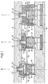
- the multi-stage deep-drawing tool shown in FIGS. 1 to 3 has (by way of example) three stations I, II and III.
- station I a blank is punched out of thin strip and drawn in a first drawing stage.
- the second drawing stage is carried out in station II, while the edge of the finished drawn product is trimmed in station III.
- Each station has an upper tool 10, 10 ′, 10 ′′ and a lower tool 12, 12 ′ and 12 ′′, all upper tools being fastened to a common crosshead 14 and all lower tools to a common base plate 16.
- an ejector 18, 18', 18 '' is provided in each upper tool, which is attached to a cylindrical guide shaft 20, 20 ', 20' 'with a widened end part 22, 22 ', 22' 'is attached.
- the vertical sliding movement of the ejector ends relative to the upper tool in each case at a stop edge 24, 24 ', 24' 'of the respective upper tool.
- Compressed air nozzles (not shown) are used to transport the products between the individual stations I, II and III along a transport plane 26, which preferably produce a laminar transport air flow, which is indicated in the figures by an arrow pointing to the left.
- the respective compressed air nozzles are not controlled individually, but are connected to a compressed air source. With suitable guidance devices, however, the transport can also be accomplished with a turbulent air flow.
- the stations II and III each have a collecting basket 28 ', 28''which is attached to the associated upper tool 10', 10 '' and moves together with it.
- Each collecting basket 28 ', 28'' is essentially U-shaped in cross section parallel to the transport plane 26, the base of the U being provided with a passage opening 30', 30 '' for the product to be transported.
- the passage opening can be selected so that a product can only pass through it if it has been processed at the associated processing station.
- Fig. 1 shows the deep-drawing tool in the closed state, i.e. the working stroke is completed and the upper tools 10, 10 'and 10' 'of all stations I, II and III are closed against the lower tools 12, 12', 12 ''. Since all the upper tools 10, 10 ′, 10 ′′ are fastened to the common crosshead 14, the working stroke and the opening stroke are carried out simultaneously for all stations.
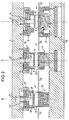
- FIG. 2 shows the deep-drawing tool from FIG. 1, but the crosshead 14 has already partially carried out the opening stroke.
- the deep-drawn products A, B and C in stations I, II and III have already been ejected from the upper tool by the ejectors 18, 18 ', 18''.
- stations I and II they are still held by the ejector on the upper side of the lower tool, since the ejectors are pressed vertically downwards by a compressed air cushion acting constantly on the upper side of the ejector stamp 20, 20 '.
- the associated compressed air nozzles are already activated here, the products A and B are still held in their station in this way.
- the ejector 18 ′′ has already released the finished deep-drawn product C, since the upper widening 22 ′′ of the ejector 18 ′′ on the stop edge 24 '' of the upper tool 10 '' struck and thus the opening stroke of the ejector has been initiated.
- the associated collecting basket 28 ′′ has been raised so far in station III that its passage opening 30 ′′ is located in the transport plane 26, so that the compressed air flow indicated by an arrow can convey the product C from station III.
- the thin strip 40 has been advanced as far as is necessary to punch out the next round blank.
- the tool it can be seen in FIG. 3 that when the tool is completely open, all the upper tools and all ejectors 18, 18 'and 18' 'are located clearly above the products, so that they can be transported unhindered.
- FIGS. 1 to 3 From the sequence of FIGS. 1 to 3 it can be seen that on the one hand the closing stroke and the opening stroke for all stations I, II and III are carried out simultaneously and that the products A, B and C processed in the stations during the opening stroke are released by the ejectors 18, 18 'and 18''at different times, since they strike their stops 24, 24' and 24 '' at different times when all the tools open simultaneously.
- Fig. 2 shows that the product C is released first, which has already passed through all processing stations, that is, the opening stroke of the ejector 18 '' begins when the tool is opened, and the opening stroke of the ejector 18 of station I begins when the Tool last.
- the transport air flow can be switched off during the working stroke (FIG. 1), but this switching of the air flow is relatively roughly oriented to the tool movement and does not require any fine adjustment during production.
- the products are guided laterally during transport by guide elements (not shown).
- the ejectors 18, 18 'and 18' 'of stations I, II and III described above have a dual function according to the invention, since on the one hand they serve to push the product out of the respective upper tool and on the other hand they are used to hold the product on the top of the associated one To hold the lower tool, which lies in the transport plane. Only from a certain open position of the tool is each ejector 18, 18 ', 18' 'carried along by the associated stop 24, 24', 24 '', whereby the respective products are released one after the other.
- the laminar air flow emerging from the air nozzles then grasps the workpiece and conveys it to the collecting basket of the subsequent station, which is matched to the external dimensions of the product in the as-yet unprocessed state.
- the product is held in position by the laminar air flow that continues to work until the tool carries out the next working stroke.
Landscapes
- Engineering & Computer Science (AREA)
- Mechanical Engineering (AREA)
- Perforating, Stamping-Out Or Severing By Means Other Than Cutting (AREA)
- Multi-Process Working Machines And Systems (AREA)
Abstract
Description
Die Erfindung betrifft ein Verfahren nach dem Oberbegriff des Anspruchs 1 und eine Vorrichtung nach dem Oberbegriff des Patentanspruchs 8.The invention relates to a method according to the preamble of claim 1 and a device according to the preamble of claim 8.
Ein derartiges Verfahren und eine derartige Vorrichtung sind aus der CH-A-613 135 bekannt. Hierbei wird zur Herstellung von Hohlkörpern aus Dünnband oder Blech, wie beispielsweise Dosen oder ähnlichen Behältern, ein flaches Ausgangsmaterial in mehreren Verformungsstufen schrittweise zur gewünschten Endgestalt umgeformt. Dies erfolgt in Mehrstufen-Tiefziehwerkzeugen. In diesen wird das Endprodukt dadurch geformt, daß der Hohlkörper schrittweise zu einer immer größeren Tiefe bei gleichzeitiger Verringerung des Außendurchmessers gezogen wird, wobei grundsätzlich eine beliebige Anzahl von Verformungsstufen vorgesehen werden kann. Die im Einzelfall benötigte Anzahl der Verformungsstufen hängt von der angestrebten Endform des Hohlkörpers und den Verformungseigenschaften des verwendeten Materials ab. In jedem Fall ist es erforderlich, das Produkt zwischen den einzelnen Tiefziehstationen zu transportieren.Such a method and such a device are known from CH-A-613 135. For the production of hollow bodies from thin strip or sheet metal, such as cans or similar containers, a flat starting material is gradually transformed into the desired final shape in several deformation stages. This is done in multi-stage deep-drawing tools. In these, the end product is shaped by gradually drawing the hollow body to an ever greater depth while simultaneously reducing the outside diameter, it being possible in principle to provide any number of deformation stages. The number of deformation stages required in an individual case depends on the desired final shape of the hollow body and the deformation properties of the material used. In any case, it is necessary to transport the product between the individual deep-drawing stations.
In der genannten CH-A-613 135 ist bereits ausgeführt, daß frühere Lösungen mit mechanischen Fördervorrichtungen aufgrund der zu bewegenden Massen solcher Vorrichtungen bei den heute geforderten Arbeitsgeschwindigkeiten nicht mehr befriedigen können. Deshalb wird in diesem Stand der Technik als Antrieb Druckluft vorgesehen. Dabei werden die Tiefziehprodukte in jeder Station gegen Positioniervorrichtungen in Form von Anschlägen bewegt, die einen Weitertransport des antransportierten Produktes verhindern, jedoch ein Durchführen des in der jeweiligen Station bearbeiteten (durchmesserverringerten) Produktes ermöglichen. Bei dieser vorbekannten Lösung ist es jedoch nachteilig, daß das Ausstoßen der Produkte aus dem Werkzeug und der Weitertransport mittels Druckluft über eine genaue Zeitfolgesteuerung koordiniert werden muß, um zu gewährleisten, daß in keiner Station bereits das nächste Produkt angeliefert wird, bevor das zuvor bearbeitete die Station verlassen hat. Bei jeder Neueinstellung der Tiefziehanlage auf ein Produkt erfordert dies aufwendige Probeläufe und Einregulierungen, die nur von fachkundigem Personal durchgeführt werden können. Das gleiche gilt für eventuell erforderliche Nachregulierungen während der Fertigung, die selbst dann notwendig werden, wenn mit veränderter Geschwindigkeit gearbeitet werden soll.In the above-mentioned CH-A-613 135 it has already been stated that previous solutions with mechanical conveying devices can no longer be satisfied due to the masses to be moved of such devices at the working speeds required today. For this reason, compressed air is provided as the drive in this prior art. The thermoformed products are countered in every station Moving positioning devices in the form of stops, which prevent further transport of the transported product, but enable the product processed (reduced diameter) to be carried out in the respective station. With this known solution, however, it is disadvantageous that the ejection of the products from the tool and the further transport by means of compressed air must be coordinated via an exact time sequence control in order to ensure that the next product is not delivered to any station before the previously processed one Has left the station. Each time the thermoforming system is reset to a product, this requires complex test runs and adjustments that can only be carried out by specialist personnel. The same applies to any readjustments that may be necessary during production, which are necessary even if you want to work at a different speed.
Auch die in der DE 26 35 583 C2, der EP 0 231 947, der EP 0 356 975 und der EP 0 149 184 beschriebenen Vorrichtungen lösen dieses Problem nicht.The devices described in
Es ist deshalb die der Erfindung zugrundeliegende Aufgabe, ein Verfahren und eine Vorrichtung der eingangs beschriebenen Art dahingehend weiterzubilden, daß ein Weitertransport der Produkte selbststeuernd bei jeder Arbeitsgeschwindigkeit gewährleistet ist, ohne daß Einstell- oder Anpassungsarbeiten erforderlich sind.It is therefore the object of the invention to further develop a method and a device of the type described in the introduction in such a way that a further transport of the products is guaranteed in a self-controlling manner at any working speed, without adjustment or adaptation work being necessary.
Die Lösung dieser Aufgabe erfolgt durch ein Verfahren mit den Merkmalen des Patentanspruchs 1, und insbesondere dadurch, daß die Produkte bei allen Bearbeitungsstufen gleichzeitig bearbeitet werden, nach der Bearbeitung zur Verhinderung des weiteren Transports zeitweise festgehalten werden und zu unterschiedlichen Zeitpunkten für einen Weitertransport freigegeben werden. Da die bearbeiteten Produkte beim Öffnungshub zu unterschiedlichen, aufeinander abgestimmten Zeitpunkten für einen Weitertransport freigegeben werden, ist sichergestellt, daß ein nachfolgendes Produkt erst dann weitertransportiert wird, wenn das vorangehende Produkt die Zielposition verlassen hat.This object is achieved by a method having the features of claim 1, and in particular in that the products are processed simultaneously in all processing stages, are temporarily held after processing to prevent further transport and are released for further transport at different times. Because the processed products at the opening stroke to different, coordinated When the time is released for further transport, it is ensured that a subsequent product is only then transported on when the preceding product has left the target position.
Vorteilhafte Ausführungsformen des erfindungsgemäßen Verfahrens sind in den Unteransprüchen 2 bis 7 angegeben.Advantageous embodiments of the method according to the invention are specified in subclaims 2 to 7.
So kann das Produkt in der Station durch einen Auswerfer aus dem Werkzeug entfernt werden. Aus der eingangs genannten CH-A-613 135 ist ein solcher Auswerfer bekannt, durch den das Produkt dort aus dem Unterwerkzeug entfernt und damit zugleich zum Weitertransport freigegeben wird. Um eine aufeinander abgestimmte Abfolge des Transports der Produkte aus den verschiedenen Stationen zu erreichen, muß im Stand der Technik eine Zeitsteuerung für die Betätigung der Auswerfer vorgesehen sein.The product can be removed from the tool by an ejector in the station. Such an ejector is known from the above-mentioned CH-A-613 135, by means of which the product is removed from the lower tool there and at the same time released for further transport. In order to achieve a coordinated sequence of the transport of the products from the various stations, a time control for actuating the ejectors must be provided in the prior art.
Erfindungsgemäß werden beim gleichzeitigen Öffnungshub aller Stationen zwar die Produkte in allen Stationen auch gleichzeitig aus den Werkzeugen entfernt, aber nicht sofort zum Weitertransport freigegeben, sondern zunächst von Niederhalteeinrichtungen, vorzugsweise den Auswerfern, auf der Oberseite der Unterwerkzeuge festgehalten, bis ein Öffnungshub der Auswerfer die endgültige Freigabe des jeweiligen Produkts zum Weitertransport bewirkt.According to the invention, the products are removed from the tools in all stations at the same time during the simultaneous opening stroke of all stations, but are not immediately released for further transport, but are first held on the top of the lower tools by hold-down devices, preferably the ejectors, until an opening stroke of the ejectors is the final one Release of the respective product for further transport.
Besonders vorteilhaft ist es, wenn die Öffnungshübe der Auswerfer zu unterschiedlichen, aufeinander abgestimmten Zeitpunkten beginnen. Hierdurch wird auf besonders einfache Weise sichergestellt, daß die in den Stationen bearbeiteten Produkte zu unterschiedlichen Zeitpunkten für einen Weitertransport freigegeben werden, da sich die Auswerfer beim Öffnungshub zu unterschiedlichen Zeitpunkten von den Produkten lösen, die in den unterschiedlichen Bearbeitungsstationen angeordnet sind.It is particularly advantageous if the opening strokes of the ejectors begin at different, coordinated times. This ensures in a particularly simple manner that the products processed in the stations are released for further transport at different times, since the ejectors at the opening stroke separate from the products which are arranged in the different processing stations at different times.
Da die Oberwerkzeuge und die Auswerfer durch das gleiche Maschinenbauteil bewegt werden, können aufwendige Stell- und Steuervorrichtungen entfallen.Since the upper tools and the ejectors are moved by the same machine component, complex adjustment and control devices can be dispensed with.
Nach einer weiteren vorteilhaften Ausbildung der Erfindung erfolgt der Antrieb der Produkte durch einen Luftstrom, der vorzugsweise während des Arbeitshubes der Vorrichtung unterbrochen wird. Zwar müßte der Luftstrom erfindungsgemäß grundsätzlich überhaupt nicht unterbrochen werden, um einen ordnungsgemäßen Produktionsablauf sicherzustellen. Jedoch kann der Luftstrom aus Kostengründen abgeschalten werden, während die Produkte beim Arbeitshub in den Werkzeugen fixiert sind. Durch die erfindungsgemäße Lösung ist es jedoch möglich, daß der Luftstrom zum Weitertransport der Produkte für alle Stationen gemeinsam gesteuert wird. Eine Einzelansteuerung kann also entfallen.According to a further advantageous embodiment of the invention, the products are driven by an air flow, which is preferably interrupted during the working stroke of the device. According to the invention, the air flow would basically not have to be interrupted at all in order to ensure a proper production process. However, the air flow can be switched off for cost reasons, while the products are fixed in the tools during the working stroke. However, the solution according to the invention makes it possible for the air flow to be controlled jointly for all stations for the further transport of the products. A single control can therefore be omitted.
In vorteilhafter Ausbildung der Erfindung werden in jeder Station Positioniervorrichtungen angeordnet, die so ausgebildet sind, daß sie die vom Luftstrom antransportierten Produkte zum Werkzeug orientiert stoppen, jedoch nach erfolgter Bearbeitung des Produktes dessen Weitertransport erlauben. Dazu sind bevorzugt entsprechend dimensionierte Durchtrittsöffnungen in den Positioniervorrichtungen vorgesehen.In an advantageous embodiment of the invention, positioning devices are arranged in each station which are designed in such a way that they stop the products transported by the air flow in an oriented manner towards the tool, but allow the product to be transported further after the product has been processed. For this purpose, appropriately dimensioned passage openings are preferably provided in the positioning devices.
Nach einer weiteren vorteilhaften Ausführungsform des erfindungsgemäßen Verfahrens wird die betreffende Positioniervorrichtung beim Öffnen des Oberwerkzeugs zwangsweise in die Transportbahn bewegt. Auch hierdurch ist gewährleistet, daß bei einer Veränderung der Arbeitsgeschwindigkeit oder der Produkte keinerlei Einstellarbeiten erforderlich sind.According to a further advantageous embodiment of the method according to the invention, the positioning device in question is forcibly moved into the transport path when the upper tool is opened. This also ensures that no adjustment work is required when changing the working speed or the products.
Die Lösung der eingangs genannten Aufgabe erfolgt ferner durch ein mehrstufiges Bearbeitungswerkzeug mit den Merkmalen des Patentanspruchs 8.The above-mentioned object is also achieved by a multi-stage machining tool with the features of claim 8.
Erfindungsgemäß sind die Oberwerkzeuge an einem gemeinsamen Querhaupt befestigt und werden von diesem in ihren Bewegungen betätigt. Hierdurch ist einerseits eine konstruktiv einfache Lösung geschaffen, da für die Hubbewegungen der einzelnen Werkzeuge keine getrennten Vorrichtungen und Ansteuerungen erforderlich sind. Ferner sind die Auswerfer in Bewegungsrichtung des Querhauptes verschiebbar an den Oberwerkzeugen angebracht, so daß auch die Auswerfer durch die Bewegungen des gemeinsamen Querhauptes betätigt werden, und auch hier gesonderte Betätigungs- und/oder Steuereinrichtungen entfallen können. Ferner sind Niederhalteeinrichtungen vorgesehen, die vorzugsweise durch die Auswerfer gebildet werden, und deren Bewegungen bezüglich der Oberwerkzeuge derart begrenzt sind, daß die Niederhalteeinrichtungen, vorzugsweise die Auswerfer, beim Öffnen des Werkzeugs zu unterschiedlichen Zeitpunkten, in zwangsläufiger Abhängigkeit vom Bewegungsablauf des Oberwerkzeugs, an dessen Öffnungshub teilnehmen. Schließlich sind die Niederhalteeinrichtungen, vorzugsweise die Auswerfer, bezüglich eines zu bearbeitenden Produkts derart angeordnet, daß sie das Produkt bis zu ihrem jeweiligen Öffnungshub festhalten. Hierdurch wird eine besonders einfache und zweckmäßige Steuerung des Weitertransports der Produkte erreicht.According to the invention, the upper tools are fastened to a common crosshead and are actuated by this in their movements. On the one hand, this creates a structurally simple solution, since no separate devices and controls are required for the lifting movements of the individual tools. Furthermore, the ejectors are slidably attached to the upper tools in the direction of movement of the crosshead, so that the ejectors are also actuated by the movements of the common crosshead, and separate actuating and / or control devices can also be omitted here. Furthermore, hold-down devices are provided, which are preferably formed by the ejectors, and whose movements with respect to the upper tools are limited in such a way that the hold-down devices, preferably the ejectors, when the tool is opened at different times, inevitably depending on the movement sequence of the upper tool, on its opening stroke take part. Finally, the hold-down devices, preferably the ejectors, are arranged with respect to a product to be processed in such a way that they hold the product up to their respective opening stroke. In this way, a particularly simple and expedient control of the further transport of the products is achieved.
Vorteilhafte Ausführungsformen der erfindungsgemäßen Vorrichtung sind durch die Unteransprüche 9 bis 17 gekennzeichnet.Advantageous embodiments of the device according to the invention are characterized by subclaims 9 to 17.
So können die Auswerfer der verschiedenen Bearbeitungsstationen so geführt sein, daß sie beim Öffnen des Oberwerkzeuges zunächst unter der Wirkung einer Niederhaltekraft in der bei Schließstellung der Werkzeuge eingenommenen Position verharren und dadurch das jeweilige Produkt auf der in der Transportebene liegenden Oberseite des zugehörigen Unterwerkzeugs festhalten, bis sie zeitlich nacheinander durch Anschläge mit den auffahrenden Oberwerkzeugen gekuppelt und von diesen gegen die Wirkung der Niederhaltekraft beim weiteren Öffnungshub mitgenommen werden. Erst mit einsetzendem Öffnungshub der Auswerfer werden die Produkte in den einzelnen Stationen zum Weitertransport freigegeben. Dies stellt eine konstruktiv sehr einfache Lösung dar, die eine aufeinander abfolgende Freigabe der Produkte ermöglicht. Auch müssen bei Veränderung der Arbeitsgeschwindigkeit keine Anpassungen erfolgen.The ejectors of the various processing stations can be designed so that when the upper tool is opened they initially remain in the position assumed when the tools are closed under the action of a hold-down force, thereby holding the respective product on the upper side of the associated lower tool in the transport plane until them in time successively coupled by stops with the upper tools in motion and taken away by them against the action of the hold-down force during the further opening stroke. The products are only released for further transport in the individual stations when the ejector opening stroke begins. This represents a structurally very simple solution, which enables the successive release of the products. Also, no changes need to be made when the working speed changes.
Jeder Auswerfer ist durch eine konstante Niederhaltekraft in Auswurfrichtung vorgespannt. Eine solche Niederhaltekraft kann beispielsweise durch eine Metallfeder oder ein Druckluftpolster bewirkt werden. Hierdurch ist sichergestellt, daß jeder Auswerfer bei Öffnen des Oberwerkzeuges das bearbeitete Produkt aus der Matrize auswirft und auf der Transportebene festhält, bis der Öffnungshub des Auswerfers einsetzt, d.h. der Auswerfer vom Produkt abgezogen wird.Each ejector is biased in the ejection direction by a constant hold-down force. Such a hold-down force can be brought about, for example, by a metal spring or a compressed air cushion. This ensures that each ejector ejects the processed product from the die when the upper tool is opened and holds it on the transport level until the ejector's opening stroke begins, i.e. the ejector is removed from the product.
Nach einer weiteren Ausführungsform der Erfindung können die Anschläge der Auswerfer einstellbar sein. Grundsätzlich ist zwar eine Nachjustage oder eine Neueinstellung der Anschläge erfindungsgemäß nicht erforderlich. Jedoch könnten die Auswerfer eine Stange aufweisen, die gleitend durch das Querhaupt geführt und oberhalb des Querhauptes mit einstellbaren Anschlägen versehen sind.According to a further embodiment of the invention, the stops of the ejectors can be adjustable. Basically, readjustment or readjustment of the stops is not necessary according to the invention. However, the ejectors could have a rod that slidably passed through the crosshead and were provided with adjustable stops above the crosshead.
Nach einer weiteren Ausbildung der Erfindung können als Antrieb für den Transport der Produkte Druckluftdüsen vorgesehen sein, die gemeinsam angesteuert werden. Da erfindungsgemäß keine Einzelansteuerung des jeweiligen Druckluftstromes erforderlich ist, läßt sich hierdurch der Steuerungsaufwand bedeutend reduzieren.According to a further embodiment of the invention, compressed air nozzles can be provided as a drive for the transport of the products, which are actuated together. Since, according to the invention, no individual control of the respective compressed air flow is required, the control effort can be significantly reduced.
Die Positioniervorrichtung für das Produkt kann nach einer weiteren Ausbildung vorteilhafterweise an dem Oberwerkzeug befestigt sein, so daß sie sich beim Öffnen des Oberwerkzeuges mit diesem bewegt. Sofern die Positioniervorrichtung für das Produkt aus einem Fangkorb besteht, der eine Durchtrittsöffnung für das Produkt aufweist, wird die Durchtrittsöffnung bei Öffnen des Oberwerkzeuges in die Transportebene bewegt, so daß das Produkt durch die Durchtrittsöffnung hindurch gefördert werden kann. Hierbei ist es vorteilhaft, wenn die Durchtrittsöffnung bei vollständig geöffnetem Oberwerkzeug oberhalb der Transportebene angeordnet ist, da dann das nachfolgende Produkt an einer Weiterbewegung gehindert ist.The positioning device for the product can, according to a further embodiment, advantageously on the upper tool be attached so that it moves when opening the upper tool with this. If the positioning device for the product consists of a collecting basket which has a passage opening for the product, the passage opening is moved into the transport plane when the upper tool is opened, so that the product can be conveyed through the passage opening. It is advantageous here if the passage opening is arranged above the transport plane when the upper tool is fully open, since the subsequent product is then prevented from moving further.
Nach einer weiteren Ausbildung der Erfindung kann der Fangkorb neben der Durchtrittsöffnung weitere Öffnungen aufweisen, um in der Luftströmung Turbulenzen zu verhindern.According to a further embodiment of the invention, the collecting basket can have further openings in addition to the passage opening in order to prevent turbulence in the air flow.
Nachfolgend wird die Erfindung beispielhaft anhand einer vorteilhaften Ausführungsform unter Bezugnahme auf die beigefügten Zeichnungen beschrieben. Es zeigen:
- Fig. 1
- eine Querschnittsansicht eines erfindungsgemäßen Mehrstufen-Tiefziehwerkzeuges mit drei Stationen in geschlossenem Zustand;
- Fig. 2
- das Tiefziehwerkzeug von Fig. 1, wobei die Oberwerkzeuge teilweise geöffnet sind; und
- Fig. 3
- das Tiefziehwerkzeug von Fig. 1 in vollständig geöffnetem Zustand.
- Fig. 1
- a cross-sectional view of a multi-stage deep-drawing tool according to the invention with three stations in the closed state;
- Fig. 2
- the deep-drawing tool of Figure 1, the upper tools are partially open. and
- Fig. 3
- 1 in the fully open state.
Das in den Fig. 1 bis 3 dargestellte Mehrstufen-Tiefziehwerkzeug weist (beispielhaft) drei Stationen I, II und III auf. Dabei wird in der Station I aus Dünnband eine Ronde ausgestanzt und in einer ersten Ziehstufe gezogen. In der Station II wird die zweite Ziehstufe ausgeführt, während in der Station III der Rand des fertig gezogenen Produktes beschnitten wird.The multi-stage deep-drawing tool shown in FIGS. 1 to 3 has (by way of example) three stations I, II and III. In station I, a blank is punched out of thin strip and drawn in a first drawing stage. The second drawing stage is carried out in station II, while the edge of the finished drawn product is trimmed in station III.
Jede Station weist ein Oberwerkzeug 10, 10', 10'' und ein Unterwerkzeug 12, 12' und 12'' auf, wobei sämtliche Oberwerkzeuge an einem gemeinsamen Querhaupt 14 und sämtliche Unterwerkzeuge an einer gemeinsamen Grundplatte 16 befestigt sind. Zum Auswerfen des Produktes aus der jeweiligen Matrize des Oberwerkzeuges 10, 10', 10'' ist in jedem Oberwerkzeug ein Auswerfer 18, 18', 18'' vorgesehen, der an einem zylindrischen Führungsschaft 20, 20', 20'' mit verbreitertem Endteil 22, 22', 22'' befestigt ist. Hierbei endet die vertikale Gleitbewegung der Auswerfer relativ zum Oberwerkzeug jeweils an einer Anschlagkante 24, 24', 24'' des jeweiligen Oberwerkzeugs.Each station has an
Zum Transport der Produkte zwischen den einzelnen Stationen I, II und III entlang einer Transportebene 26 dienen (nicht dargestellte) Druckluftdüsen, die einen vorzugsweise laminaren Transport-Luftstrom erzeugen, der in den Figuren jeweils durch einen nach links gerichteten Pfeil angedeutet ist. Die jeweiligen Druckluftdüsen sind nicht einzeln angesteuert, sondern gemeinsam mit einer Druckluftquelle verbunden. Mit geeigneten Leitvorrichtungen kann der Transport allerdings auch mit einer turbulenten Luftströmung bewerkstelligt werden.Compressed air nozzles (not shown) are used to transport the products between the individual stations I, II and III along a
Als Positioniervorrichtung für die weiterzutransportierenden Produkte weisen die Stationen II und III jeweils einen Fangkorb 28', 28'' auf, der an dem zugehörigen Oberwerkzeug 10', 10'' befestigt ist und sich zusammen mit diesem bewegt. Jeder Fangkorb 28', 28'' ist im Querschnitt parallel zur Transportebene 26 im wesentlichen U-förmig ausgebildet, wobei die Basis des U mit einer Durchtrittsöffnung 30', 30'' für das zu transportierende Produkt versehen ist. Hierbei kann die Durchtrittsöffnung so gewählt sein, daß ein Produkt nur dann durch diese hindurchgelangen kann, wenn es an der zugehörigen Bearbeitungsstation bearbeitet worden ist. Unterhalb der Durchtrittsöffnungen 30', 30'' sind weitere Öffnungen (nicht dargestellt) vorgesehen, die das Auftreten von Turbulenzen in der Transportluftströmung vermeiden.As a positioning device for the products to be transported further, the stations II and III each have a collecting basket 28 ', 28''which is attached to the associated upper tool 10', 10 '' and moves together with it. Each collecting basket 28 ', 28''is essentially U-shaped in cross section parallel to the
Nachfolgend wird die Funktionsweise der in den Fig. 1 bis 3 dargestellten Vorrichtung beschrieben.The mode of operation of the device shown in FIGS. 1 to 3 is described below.
Bei dem in den Fig. 1 bis 3 dargestellten Drei-Stationen-Tiefziehwerkzeug wird in der Station I aus Dünnbandmaterial eine Ronde ausgestanzt und die erste Tiefziehstufe durchgeführt. Nach dem Transport des in der Station I bearbeiteten Produktes zur Station II wird es dort einem weiteren Tiefziehvorgang unterworfen und anschließend zum Beschneiden des Randes in die Station III überführt.In the three-station deep-drawing tool shown in FIGS. 1 to 3, a round blank is punched out of thin strip material in station I and the first deep-drawing stage is carried out. After the product processed in station I has been transported to station II, it is subjected to a further deep-drawing process and then transferred to station III for trimming the edge.
Fig. 1 zeigt das Tiefziehwerkzeug in geschlossenem Zustand, d.h. der Arbeitshub ist vollständig durchgeführt und die Oberwerkzeuge 10, 10' und 10'' sämtlicher Stationen I, II und III sind gegen die Unterwerkzeuge 12, 12', 12'' geschlossen. Da sämtliche Oberwerkzeuge 10, 10', 10'' an dem gemeinsamen Querhaupt 14 befestigt sind, werden der Arbeitshub wie auch der Öffnungshub für alle Stationen gleichzeitig durchgeführt.Fig. 1 shows the deep-drawing tool in the closed state, i.e. the working stroke is completed and the
Fig. 2 zeigt das Tiefziehwerkzeug von Fig. 1, wobei jedoch das Querhaupt 14 den Öffnungshub bereits teilweise durchgeführt hat. Dadurch sind die Tiefziehprodukte A, B und C in den Stationen I, II und III bereits von den Auswerfern 18, 18', 18'' aus dem Oberwerkzeug ausgestoßen. In den Stationen I und II werden sie noch vom Auswerfer auf der Oberseite des Unterwerkzeuges festgehalten, da die Auswerfer durch ein auf der Oberseite des Auswerferstempels 20, 20' konstant wirkendes Druckluftpolster vertikal nach unten gedrückt werden. Obwohl auch hier bereits die zugehörigen Druckluftdüsen aktiviert sind, werden die Produkte A und B auf diese Weise noch in ihrer Station gehalten. In der Station III hat jedoch der Auswerfer 18'' das fertige Tiefziehprodukt C bereits freigegeben, da die obere Verbreiterung 22'' des Auswerfers 18'' an der Anschlagskante 24'' des Oberwerkzeugs 10'' angeschlagen und damit der Öffnungshub des Auswerfers eingeleitet worden ist. Gleichzeitig ist in der Station III der zugehörige Fangkorb 28'' so weit angehoben worden, daß sich dessen Durchtrittsöffnung 30'' in der Transportebene 26 befindet, so daß der mit einem Pfeil angedeutete Druckluftstrom das Produkt C aus der Station III fördern kann.FIG. 2 shows the deep-drawing tool from FIG. 1, but the
Fig. 3 zeigt schließlich das Tiefziehwerkzeug in vollständig geöffnetem Zustand. Wie gut zu erkennen ist, ist das fertige Produkt C durch den Luftstrom bereits aus der Station III ausgestoßen worden und das Produkt B ist an dessen Stelle nachgerückt. Da sich die Durchtrittsöffnung 30'' des Fangkorbes 28'' der Station III jetzt oberhalb der Transportebene 26 befindet, schlägt das Produkt B an den Fangkorb 28'' an und wird von dem zugehörigen Transport-Luftstrom nicht weitergefördert, sondern in seiner Position fixiert.3 finally shows the deep-drawing tool in the fully open state. As can be clearly seen, the finished product C has already been expelled from the station III by the air stream and the product B has moved in its place. Since the
In der Station II ist zu erkennen, daß das Produkt A von dem zugehörigen Druckluftstrom in den Fangkorb 28' hineinbewegt wird und an diesem fixiert wird, da sich die Durchtrittsöffnung 30' ebenfalls oberhalb der Transportebene 26 befindet.In station II it can be seen that the product A is moved into the collecting basket 28 'by the associated compressed air flow and is fixed thereon, since the
In der Station I ist das Dünnband 40 so weit vorgeschoben worden, wie es zum Ausstanzen der nächsten Ronde erforderlich ist. Gleichzeitig ist in Fig. 3 zu erkennen, daß sich bei vollständig geöffnetem Werkzeug sämtliche Oberwerkzeuge und sämtliche Auswerfer 18, 18' und 18'' deutlich oberhalb der Produkte befinden, so daß diese ungehindert transportiert werden können.In station I, the
Aus der Abfolge der Fig. 1 bis 3 geht hervor, daß einerseits der Schließhub und der Öffnungshub für alle Stationen I, II und III gleichzeitig durchgeführt werden und daß die in den Stationen bearbeiteten Produkte A, B und C beim Öffnungshub zu unterschiedlichen Zeitpunkten von den Auswerfern 18, 18' und 18'' freigegeben werden, da diese beim zeitgleichen Öffnungshub aller Werkzeuge zu unterschiedlichen Zeitpunkten an ihren Anschlägen 24, 24' und 24'' anschlagen. Fig. 2 läßt erkennen, daß als erstes das Produkt C freigegeben wird, das bereits sämtliche Bearbeitungsstationen durchlaufen hat, d.h. der Öffnungshub des Auswerfers 18'' beginnt bei Öffnen des Werkzeuges zuerst, und der Öffnungshub des Auswerfers 18 der Station I beginnt bei Öffnen des Werkzeuges zuletzt.From the sequence of FIGS. 1 to 3 it can be seen that on the one hand the closing stroke and the opening stroke for all stations I, II and III are carried out simultaneously and that the products A, B and C processed in the stations during the opening stroke are released by the
Während des Arbeitshubes (Fig. 1) kann der Transport-Luftstrom abgeschaltet werden, wobei diese Schaltung des Luftstroms jedoch zur Werkzeugbewegung relativ grob orientiert ist und keiner Feineinstellung während der Produktion bedarf. Die seitliche Führung der Produkte während des Transportes erfolgt durch nicht dargestellte Führungselemente.The transport air flow can be switched off during the working stroke (FIG. 1), but this switching of the air flow is relatively roughly oriented to the tool movement and does not require any fine adjustment during production. The products are guided laterally during transport by guide elements (not shown).
Die oben beschriebenen Auswerfer 18, 18' und 18'' der Stationen I, II und III besitzen erfindungsgemäß eine Doppelfunktion, da diese einerseits dazu dienen, das Produkt aus dem jeweiligen Oberwerkzeug herauszudrücken und andererseits dazu herangezogen werden, das Produkt auf der Oberseite des zugehörigen Unterwerkzeuges festzuhalten, die in der Transportebene liegt. Erst ab einer bestimmten Öffnungsstellung des Werkzeuges wird jeder Auswerfer 18, 18', 18'' durch den zugeordneten Anschlag 24, 24', 24'' mitgenommen, wodurch die jeweiligen Produkte nacheinander freigegeben werden. Der von den Luftdüsen ausgehende laminare Luftstrom erfaßt dann das Werkstück und befördert ihn auf den Fangkorb der nachfolgenden Station zu, der auf die Außenabmessungen des Produktes im noch nicht bearbeiteten Zustand abgestimmt ist. Hier wird das Produkt von dem weiterhin wirkenden laminaren Luftstrom in Position gehalten, bis das Werkzeug den nächsten Arbeitshub durchführt.The
Claims (17)
dadurch gekennzeichnet, daß
characterized in that
dadurch gekennzeichnet, daß zumindest in einer Station das Produkt vor dem Produkt in der in der Bearbeitungsfolge vorangehenden Station freigegeben wird.Method according to claim 1,
characterized in that at least in one station the product is released before the product in the station preceding the processing sequence.
dadurch gekennzeichnet, daß
characterized in that
dadurch gekennzeichnet, daß beim Öffnungshub des Oberwerkzeugs (10, 10', 10'') zunächst der Auswerfer (18, 18', 18'') unter der Wirkung einer Niederhaltekraft in der bei der Schließstellung des Werkzeugs eingenommenen Position bleibt, bis er durch einen Anschlag (24, 24', 24'') mit dem Oberwerkzeug gekuppelt und von diesem gegen die Wirkung der Niederhaltekraft beim weiteren Öffnungshub mitgenommen wird.Device according to claim 8,
characterized in that, during the opening stroke of the upper tool (10, 10 ', 10''), the ejector (18, 18', 18 '') initially remains in the position assumed when the tool is in the closed position under the action of a hold-down force until it passes through a stop (24, 24 ', 24'') is coupled to the upper tool and is carried by it against the action of the hold-down force during the further opening stroke.
dadurch gekennzeichnet, daß die Niederhaltekraft von einer Feder oder einem konstant wirkenden Druckluftpolster erzeugt wird.Device according to claim 9,
characterized in that the hold-down force is generated by a spring or a constantly acting compressed air cushion.
Applications Claiming Priority (2)
| Application Number | Priority Date | Filing Date | Title |
|---|---|---|---|
| DE19616560 | 1996-04-25 | ||
| DE1996116560 DE19616560A1 (en) | 1996-04-25 | 1996-04-25 | Method and device for multi-stage processing of a product |
Publications (1)
| Publication Number | Publication Date |
|---|---|
| EP0803302A1 true EP0803302A1 (en) | 1997-10-29 |
Family
ID=7792437
Family Applications (1)
| Application Number | Title | Priority Date | Filing Date |
|---|---|---|---|
| EP97102456A Withdrawn EP0803302A1 (en) | 1996-04-25 | 1997-02-14 | Method and apparatus for working a product in several stages |
Country Status (2)
| Country | Link |
|---|---|
| EP (1) | EP0803302A1 (en) |
| DE (1) | DE19616560A1 (en) |
Cited By (8)
| Publication number | Priority date | Publication date | Assignee | Title |
|---|---|---|---|---|
| CN102962369A (en) * | 2012-11-26 | 2013-03-13 | 四川长虹电器股份有限公司 | Manipulator structure for automatic material loading and unloading of punch press |
| CN104985072A (en) * | 2015-05-28 | 2015-10-21 | 成都宏明双新科技股份有限公司 | Method for synchronously processing dual belt materials |
| CN106141022A (en) * | 2016-07-29 | 2016-11-23 | 江门市安诺特炊具制造有限公司 | Cooker three station link robot manipulator punch line |
| CN106944523A (en) * | 2015-09-29 | 2017-07-14 | 葛云龙 | A kind of method of work of punch press |
| CN113441590A (en) * | 2021-06-30 | 2021-09-28 | 舟山海山机械密封材料股份有限公司 | Manufacturing process and equipment of automobile engine heat shield |
| CN113458232A (en) * | 2021-07-08 | 2021-10-01 | 东莞市建星实业有限公司 | Tensile bucket production system |
| US11517956B2 (en) * | 2020-03-10 | 2022-12-06 | Fords Packaging Systems Limited | Bottle, cap and machine |
| EP4631641A1 (en) * | 2024-04-12 | 2025-10-15 | Saeta GmbH & Co. KG | Device and method for deep-drawing of cup-shaped workpieces |
Citations (2)
| Publication number | Priority date | Publication date | Assignee | Title |
|---|---|---|---|---|
| CH613135A5 (en) * | 1975-04-09 | 1979-09-14 | Stolle Corp | |
| US5062287A (en) * | 1990-01-19 | 1991-11-05 | Dayton Reliable Tool & Mfg. Co. | Method and apparatus for making and transferring shells for cans |
-
1996
- 1996-04-25 DE DE1996116560 patent/DE19616560A1/en not_active Withdrawn
-
1997
- 1997-02-14 EP EP97102456A patent/EP0803302A1/en not_active Withdrawn
Patent Citations (2)
| Publication number | Priority date | Publication date | Assignee | Title |
|---|---|---|---|---|
| CH613135A5 (en) * | 1975-04-09 | 1979-09-14 | Stolle Corp | |
| US5062287A (en) * | 1990-01-19 | 1991-11-05 | Dayton Reliable Tool & Mfg. Co. | Method and apparatus for making and transferring shells for cans |
Cited By (12)
| Publication number | Priority date | Publication date | Assignee | Title |
|---|---|---|---|---|
| CN102962369A (en) * | 2012-11-26 | 2013-03-13 | 四川长虹电器股份有限公司 | Manipulator structure for automatic material loading and unloading of punch press |
| CN102962369B (en) * | 2012-11-26 | 2015-07-29 | 四川长虹电器股份有限公司 | A kind of robot manipulator structure for punch press automatic loading/unloading |
| CN104985072A (en) * | 2015-05-28 | 2015-10-21 | 成都宏明双新科技股份有限公司 | Method for synchronously processing dual belt materials |
| WO2016188420A1 (en) * | 2015-05-28 | 2016-12-01 | 成都宏明双新科技股份有限公司 | Method for simultaneously processing materials on dual belts |
| US10343202B2 (en) | 2015-05-28 | 2019-07-09 | Chengdu Homin Technology Co., Ltd. | Method for synchronously processing dual belt materials |
| CN106944523A (en) * | 2015-09-29 | 2017-07-14 | 葛云龙 | A kind of method of work of punch press |
| CN106141022A (en) * | 2016-07-29 | 2016-11-23 | 江门市安诺特炊具制造有限公司 | Cooker three station link robot manipulator punch line |
| US11517956B2 (en) * | 2020-03-10 | 2022-12-06 | Fords Packaging Systems Limited | Bottle, cap and machine |
| CN113441590A (en) * | 2021-06-30 | 2021-09-28 | 舟山海山机械密封材料股份有限公司 | Manufacturing process and equipment of automobile engine heat shield |
| CN113441590B (en) * | 2021-06-30 | 2023-01-24 | 舟山海山机械密封材料股份有限公司 | Manufacturing process and equipment of automobile engine heat shield |
| CN113458232A (en) * | 2021-07-08 | 2021-10-01 | 东莞市建星实业有限公司 | Tensile bucket production system |
| EP4631641A1 (en) * | 2024-04-12 | 2025-10-15 | Saeta GmbH & Co. KG | Device and method for deep-drawing of cup-shaped workpieces |
Also Published As
| Publication number | Publication date |
|---|---|
| DE19616560A1 (en) | 1997-11-06 |
Similar Documents
| Publication | Publication Date | Title |
|---|---|---|
| DE2614422C3 (en) | Device for the step-by-step production of seamless cans | |
| DE19621682C2 (en) | Method and tool for ejecting sheet metal parts from a punch | |
| EP0773077B1 (en) | Press with combined transfer device | |
| DE3111098C2 (en) | Removal device for the production of containers from sheet metal | |
| CH654497A5 (en) | PUNCHING AND FORMING DEVICE FOR PRODUCING DEEP-DRAWN CUP-SHAPED CONTAINERS AND METHOD FOR THEIR OPERATION. | |
| EP0696486B1 (en) | Method and device for bending sheet metal blanks | |
| EP1012087B1 (en) | Device for outward guidance of articles transported on a conveyer | |
| EP0758285A1 (en) | Device for use in a press for feeding fastening components and for securing these components by pressing in work pieces | |
| EP0803302A1 (en) | Method and apparatus for working a product in several stages | |
| DE2635583C2 (en) | Method and device for the transport of essentially cylindrical, thin-walled hollow bodies | |
| DE3841683A1 (en) | Apparatus for cutting out and, if required, simultaneously forming parts from sheet plates | |
| DE7827272U1 (en) | FEED DEVICE | |
| CH641698A5 (en) | Press for the funnel-shaped ends of aerosols | |
| DE19545129C2 (en) | Device for the production of rod-shaped objects | |
| DE102017118654A1 (en) | Ironing arrangement, forming device with a Abstreckwerkzeuganordnung and method for forming a cup-shaped output part | |
| DE2243007C3 (en) | Method and device for the production of hollow bodies with a side seam produced by gluing | |
| DE19901304B4 (en) | Method and device for machining workpieces | |
| DE3218132A1 (en) | Method and device for punching at least two mutually coaxial sheet-metal parts | |
| DE2009138A1 (en) | Sheet stamping transfer device | |
| DE4406413C1 (en) | Assembly for unstacking stacked non-ferrous metal plates | |
| DE19756469A1 (en) | Punch press for stamping work pieces | |
| DE2229271A1 (en) | Automatic forging press - for making - components from continuous bar | |
| DE2365032B2 (en) | Device for removing excess material from blown hollow plastic objects | |
| DE3436953C2 (en) | Device with one tool both for cutting holes and for subsequently inserting eyelets and clamping disks | |
| DE1948744B2 (en) | Feeding device for a punch press for punching two concentric workpieces from sheet metal |
Legal Events
| Date | Code | Title | Description |
|---|---|---|---|
| PUAI | Public reference made under article 153(3) epc to a published international application that has entered the european phase |
Free format text: ORIGINAL CODE: 0009012 |
|
| AK | Designated contracting states |
Kind code of ref document: A1 Designated state(s): BE CH DE DK ES GB IT LI NL |
|
| 17P | Request for examination filed |
Effective date: 19971128 |
|
| STAA | Information on the status of an ep patent application or granted ep patent |
Free format text: STATUS: THE APPLICATION HAS BEEN WITHDRAWN |
|
| 18W | Application withdrawn |
Withdrawal date: 19990205 |
|
| REG | Reference to a national code |
Ref country code: HK Ref legal event code: WD Ref document number: 1001202 Country of ref document: HK |