EP0803302A1 - Méthode et dispositif pour travailler un produit en plusieurs étapes - Google Patents
Méthode et dispositif pour travailler un produit en plusieurs étapes Download PDFInfo
- Publication number
- EP0803302A1 EP0803302A1 EP97102456A EP97102456A EP0803302A1 EP 0803302 A1 EP0803302 A1 EP 0803302A1 EP 97102456 A EP97102456 A EP 97102456A EP 97102456 A EP97102456 A EP 97102456A EP 0803302 A1 EP0803302 A1 EP 0803302A1
- Authority
- EP
- European Patent Office
- Prior art keywords
- product
- tool
- station
- transport
- ejector
- Prior art date
- Legal status (The legal status is an assumption and is not a legal conclusion. Google has not performed a legal analysis and makes no representation as to the accuracy of the status listed.)
- Withdrawn
Links
- 238000000034 method Methods 0.000 title claims abstract description 15
- 238000003754 machining Methods 0.000 claims description 3
- 238000003672 processing method Methods 0.000 claims 1
- 238000004080 punching Methods 0.000 claims 1
- 239000000047 product Substances 0.000 description 64
- 238000004519 manufacturing process Methods 0.000 description 4
- 239000000463 material Substances 0.000 description 2
- 239000002184 metal Substances 0.000 description 2
- 230000006978 adaptation Effects 0.000 description 1
- 239000007795 chemical reaction product Substances 0.000 description 1
- 230000009977 dual effect Effects 0.000 description 1
- 239000007858 starting material Substances 0.000 description 1
- 238000003856 thermoforming Methods 0.000 description 1
- 238000009966 trimming Methods 0.000 description 1
Images

Classifications
-
- B—PERFORMING OPERATIONS; TRANSPORTING
- B21—MECHANICAL METAL-WORKING WITHOUT ESSENTIALLY REMOVING MATERIAL; PUNCHING METAL
- B21D—WORKING OR PROCESSING OF SHEET METAL OR METAL TUBES, RODS OR PROFILES WITHOUT ESSENTIALLY REMOVING MATERIAL; PUNCHING METAL
- B21D45/00—Ejecting or stripping-off devices arranged in machines or tools dealt with in this subclass
- B21D45/02—Ejecting devices
-
- B—PERFORMING OPERATIONS; TRANSPORTING
- B21—MECHANICAL METAL-WORKING WITHOUT ESSENTIALLY REMOVING MATERIAL; PUNCHING METAL
- B21D—WORKING OR PROCESSING OF SHEET METAL OR METAL TUBES, RODS OR PROFILES WITHOUT ESSENTIALLY REMOVING MATERIAL; PUNCHING METAL
- B21D22/00—Shaping without cutting, by stamping, spinning, or deep-drawing
- B21D22/20—Deep-drawing
- B21D22/26—Deep-drawing for making peculiarly, e.g. irregularly, shaped articles
-
- B—PERFORMING OPERATIONS; TRANSPORTING
- B21—MECHANICAL METAL-WORKING WITHOUT ESSENTIALLY REMOVING MATERIAL; PUNCHING METAL
- B21D—WORKING OR PROCESSING OF SHEET METAL OR METAL TUBES, RODS OR PROFILES WITHOUT ESSENTIALLY REMOVING MATERIAL; PUNCHING METAL
- B21D43/00—Feeding, positioning or storing devices combined with, or arranged in, or specially adapted for use in connection with, apparatus for working or processing sheet metal, metal tubes or metal profiles; Associations therewith of cutting devices
- B21D43/02—Advancing work in relation to the stroke of the die or tool
- B21D43/18—Advancing work in relation to the stroke of the die or tool by means in pneumatic or magnetic engagement with the work
Definitions
- the invention relates to a method according to the preamble of claim 1 and a device according to the preamble of claim 8.
- Such a method and such a device are known from CH-A-613 135.
- a flat starting material is gradually transformed into the desired final shape in several deformation stages. This is done in multi-stage deep-drawing tools.
- the end product is shaped by gradually drawing the hollow body to an ever greater depth while simultaneously reducing the outside diameter, it being possible in principle to provide any number of deformation stages.
- the number of deformation stages required in an individual case depends on the desired final shape of the hollow body and the deformation properties of the material used. In any case, it is necessary to transport the product between the individual deep-drawing stations.
- the product can be removed from the tool by an ejector in the station.
- an ejector is known from the above-mentioned CH-A-613 135, by means of which the product is removed from the lower tool there and at the same time released for further transport.
- a time control for actuating the ejectors must be provided in the prior art.
- the products are removed from the tools in all stations at the same time during the simultaneous opening stroke of all stations, but are not immediately released for further transport, but are first held on the top of the lower tools by hold-down devices, preferably the ejectors, until an opening stroke of the ejectors is the final one Release of the respective product for further transport.
- the opening strokes of the ejectors begin at different, coordinated times. This ensures in a particularly simple manner that the products processed in the stations are released for further transport at different times, since the ejectors at the opening stroke separate from the products which are arranged in the different processing stations at different times.
- the products are driven by an air flow, which is preferably interrupted during the working stroke of the device.
- the air flow would basically not have to be interrupted at all in order to ensure a proper production process.
- the air flow can be switched off for cost reasons, while the products are fixed in the tools during the working stroke.
- the solution according to the invention makes it possible for the air flow to be controlled jointly for all stations for the further transport of the products. A single control can therefore be omitted.
- positioning devices are arranged in each station which are designed in such a way that they stop the products transported by the air flow in an oriented manner towards the tool, but allow the product to be transported further after the product has been processed.
- appropriately dimensioned passage openings are preferably provided in the positioning devices.
- the positioning device in question is forcibly moved into the transport path when the upper tool is opened. This also ensures that no adjustment work is required when changing the working speed or the products.
- the upper tools are fastened to a common crosshead and are actuated by this in their movements.
- this creates a structurally simple solution, since no separate devices and controls are required for the lifting movements of the individual tools.
- the ejectors are slidably attached to the upper tools in the direction of movement of the crosshead, so that the ejectors are also actuated by the movements of the common crosshead, and separate actuating and / or control devices can also be omitted here.
- hold-down devices are provided, which are preferably formed by the ejectors, and whose movements with respect to the upper tools are limited in such a way that the hold-down devices, preferably the ejectors, when the tool is opened at different times, inevitably depending on the movement sequence of the upper tool, on its opening stroke take part.
- the hold-down devices preferably the ejectors, are arranged with respect to a product to be processed in such a way that they hold the product up to their respective opening stroke. In this way, a particularly simple and expedient control of the further transport of the products is achieved.
- the ejectors of the various processing stations can be designed so that when the upper tool is opened they initially remain in the position assumed when the tools are closed under the action of a hold-down force, thereby holding the respective product on the upper side of the associated lower tool in the transport plane until them in time successively coupled by stops with the upper tools in motion and taken away by them against the action of the hold-down force during the further opening stroke.
- the products are only released for further transport in the individual stations when the ejector opening stroke begins. This represents a structurally very simple solution, which enables the successive release of the products. Also, no changes need to be made when the working speed changes.
- Each ejector is biased in the ejection direction by a constant hold-down force.
- a hold-down force can be brought about, for example, by a metal spring or a compressed air cushion. This ensures that each ejector ejects the processed product from the die when the upper tool is opened and holds it on the transport level until the ejector's opening stroke begins, i.e. the ejector is removed from the product.
- the stops of the ejectors can be adjustable. Basically, readjustment or readjustment of the stops is not necessary according to the invention.
- the ejectors could have a rod that slidably passed through the crosshead and were provided with adjustable stops above the crosshead.
- compressed air nozzles can be provided as a drive for the transport of the products, which are actuated together. Since, according to the invention, no individual control of the respective compressed air flow is required, the control effort can be significantly reduced.
- the positioning device for the product can, according to a further embodiment, advantageously on the upper tool be attached so that it moves when opening the upper tool with this. If the positioning device for the product consists of a collecting basket which has a passage opening for the product, the passage opening is moved into the transport plane when the upper tool is opened, so that the product can be conveyed through the passage opening. It is advantageous here if the passage opening is arranged above the transport plane when the upper tool is fully open, since the subsequent product is then prevented from moving further.
- the collecting basket can have further openings in addition to the passage opening in order to prevent turbulence in the air flow.
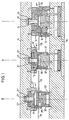
- the multi-stage deep-drawing tool shown in FIGS. 1 to 3 has (by way of example) three stations I, II and III.
- station I a blank is punched out of thin strip and drawn in a first drawing stage.
- the second drawing stage is carried out in station II, while the edge of the finished drawn product is trimmed in station III.
- Each station has an upper tool 10, 10 ′, 10 ′′ and a lower tool 12, 12 ′ and 12 ′′, all upper tools being fastened to a common crosshead 14 and all lower tools to a common base plate 16.
- an ejector 18, 18', 18 '' is provided in each upper tool, which is attached to a cylindrical guide shaft 20, 20 ', 20' 'with a widened end part 22, 22 ', 22' 'is attached.
- the vertical sliding movement of the ejector ends relative to the upper tool in each case at a stop edge 24, 24 ', 24' 'of the respective upper tool.
- Compressed air nozzles (not shown) are used to transport the products between the individual stations I, II and III along a transport plane 26, which preferably produce a laminar transport air flow, which is indicated in the figures by an arrow pointing to the left.
- the respective compressed air nozzles are not controlled individually, but are connected to a compressed air source. With suitable guidance devices, however, the transport can also be accomplished with a turbulent air flow.
- the stations II and III each have a collecting basket 28 ', 28''which is attached to the associated upper tool 10', 10 '' and moves together with it.
- Each collecting basket 28 ', 28'' is essentially U-shaped in cross section parallel to the transport plane 26, the base of the U being provided with a passage opening 30', 30 '' for the product to be transported.
- the passage opening can be selected so that a product can only pass through it if it has been processed at the associated processing station.
- Fig. 1 shows the deep-drawing tool in the closed state, i.e. the working stroke is completed and the upper tools 10, 10 'and 10' 'of all stations I, II and III are closed against the lower tools 12, 12', 12 ''. Since all the upper tools 10, 10 ′, 10 ′′ are fastened to the common crosshead 14, the working stroke and the opening stroke are carried out simultaneously for all stations.
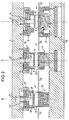
- FIG. 2 shows the deep-drawing tool from FIG. 1, but the crosshead 14 has already partially carried out the opening stroke.
- the deep-drawn products A, B and C in stations I, II and III have already been ejected from the upper tool by the ejectors 18, 18 ', 18''.
- stations I and II they are still held by the ejector on the upper side of the lower tool, since the ejectors are pressed vertically downwards by a compressed air cushion acting constantly on the upper side of the ejector stamp 20, 20 '.
- the associated compressed air nozzles are already activated here, the products A and B are still held in their station in this way.
- the ejector 18 ′′ has already released the finished deep-drawn product C, since the upper widening 22 ′′ of the ejector 18 ′′ on the stop edge 24 '' of the upper tool 10 '' struck and thus the opening stroke of the ejector has been initiated.
- the associated collecting basket 28 ′′ has been raised so far in station III that its passage opening 30 ′′ is located in the transport plane 26, so that the compressed air flow indicated by an arrow can convey the product C from station III.
- the thin strip 40 has been advanced as far as is necessary to punch out the next round blank.
- the tool it can be seen in FIG. 3 that when the tool is completely open, all the upper tools and all ejectors 18, 18 'and 18' 'are located clearly above the products, so that they can be transported unhindered.
- FIGS. 1 to 3 From the sequence of FIGS. 1 to 3 it can be seen that on the one hand the closing stroke and the opening stroke for all stations I, II and III are carried out simultaneously and that the products A, B and C processed in the stations during the opening stroke are released by the ejectors 18, 18 'and 18''at different times, since they strike their stops 24, 24' and 24 '' at different times when all the tools open simultaneously.
- Fig. 2 shows that the product C is released first, which has already passed through all processing stations, that is, the opening stroke of the ejector 18 '' begins when the tool is opened, and the opening stroke of the ejector 18 of station I begins when the Tool last.
- the transport air flow can be switched off during the working stroke (FIG. 1), but this switching of the air flow is relatively roughly oriented to the tool movement and does not require any fine adjustment during production.
- the products are guided laterally during transport by guide elements (not shown).
- the ejectors 18, 18 'and 18' 'of stations I, II and III described above have a dual function according to the invention, since on the one hand they serve to push the product out of the respective upper tool and on the other hand they are used to hold the product on the top of the associated one To hold the lower tool, which lies in the transport plane. Only from a certain open position of the tool is each ejector 18, 18 ', 18' 'carried along by the associated stop 24, 24', 24 '', whereby the respective products are released one after the other.
- the laminar air flow emerging from the air nozzles then grasps the workpiece and conveys it to the collecting basket of the subsequent station, which is matched to the external dimensions of the product in the as-yet unprocessed state.
- the product is held in position by the laminar air flow that continues to work until the tool carries out the next working stroke.
Landscapes
- Engineering & Computer Science (AREA)
- Mechanical Engineering (AREA)
- Multi-Process Working Machines And Systems (AREA)
- Perforating, Stamping-Out Or Severing By Means Other Than Cutting (AREA)
Applications Claiming Priority (2)
| Application Number | Priority Date | Filing Date | Title |
|---|---|---|---|
| DE1996116560 DE19616560A1 (de) | 1996-04-25 | 1996-04-25 | Verfahren und Vorrichtung zum mehrstufigen Bearbeiten eines Produktes |
| DE19616560 | 1996-04-25 |
Publications (1)
| Publication Number | Publication Date |
|---|---|
| EP0803302A1 true EP0803302A1 (fr) | 1997-10-29 |
Family
ID=7792437
Family Applications (1)
| Application Number | Title | Priority Date | Filing Date |
|---|---|---|---|
| EP97102456A Withdrawn EP0803302A1 (fr) | 1996-04-25 | 1997-02-14 | Méthode et dispositif pour travailler un produit en plusieurs étapes |
Country Status (2)
| Country | Link |
|---|---|
| EP (1) | EP0803302A1 (fr) |
| DE (1) | DE19616560A1 (fr) |
Cited By (8)
| Publication number | Priority date | Publication date | Assignee | Title |
|---|---|---|---|---|
| CN102962369A (zh) * | 2012-11-26 | 2013-03-13 | 四川长虹电器股份有限公司 | 一种用于冲床自动上下料的机械手结构 |
| CN104985072A (zh) * | 2015-05-28 | 2015-10-21 | 成都宏明双新科技股份有限公司 | 一种同时对双带料进行加工的方法 |
| CN106141022A (zh) * | 2016-07-29 | 2016-11-23 | 江门市安诺特炊具制造有限公司 | 炊具三工位连杆机械手冲压线 |
| CN106944523A (zh) * | 2015-09-29 | 2017-07-14 | 葛云龙 | 一种冲床的工作方法 |
| CN113441590A (zh) * | 2021-06-30 | 2021-09-28 | 舟山海山机械密封材料股份有限公司 | 一种汽车发动机隔热罩的制造工艺及设备 |
| CN113458232A (zh) * | 2021-07-08 | 2021-10-01 | 东莞市建星实业有限公司 | 一种拉伸桶生产系统 |
| US11517956B2 (en) * | 2020-03-10 | 2022-12-06 | Fords Packaging Systems Limited | Bottle, cap and machine |
| EP4631641A1 (fr) * | 2024-04-12 | 2025-10-15 | Saeta GmbH & Co. KG | Dispositif et procédé d'emboutissage de pièces en forme de cuvette |
Citations (2)
| Publication number | Priority date | Publication date | Assignee | Title |
|---|---|---|---|---|
| CH613135A5 (fr) * | 1975-04-09 | 1979-09-14 | Stolle Corp | |
| US5062287A (en) * | 1990-01-19 | 1991-11-05 | Dayton Reliable Tool & Mfg. Co. | Method and apparatus for making and transferring shells for cans |
-
1996
- 1996-04-25 DE DE1996116560 patent/DE19616560A1/de not_active Withdrawn
-
1997
- 1997-02-14 EP EP97102456A patent/EP0803302A1/fr not_active Withdrawn
Patent Citations (2)
| Publication number | Priority date | Publication date | Assignee | Title |
|---|---|---|---|---|
| CH613135A5 (fr) * | 1975-04-09 | 1979-09-14 | Stolle Corp | |
| US5062287A (en) * | 1990-01-19 | 1991-11-05 | Dayton Reliable Tool & Mfg. Co. | Method and apparatus for making and transferring shells for cans |
Cited By (12)
| Publication number | Priority date | Publication date | Assignee | Title |
|---|---|---|---|---|
| CN102962369A (zh) * | 2012-11-26 | 2013-03-13 | 四川长虹电器股份有限公司 | 一种用于冲床自动上下料的机械手结构 |
| CN102962369B (zh) * | 2012-11-26 | 2015-07-29 | 四川长虹电器股份有限公司 | 一种用于冲床自动上下料的机械手结构 |
| CN104985072A (zh) * | 2015-05-28 | 2015-10-21 | 成都宏明双新科技股份有限公司 | 一种同时对双带料进行加工的方法 |
| WO2016188420A1 (fr) * | 2015-05-28 | 2016-12-01 | 成都宏明双新科技股份有限公司 | Procédé pour le traitement simultané de matériaux sur des bandes doubles |
| US10343202B2 (en) | 2015-05-28 | 2019-07-09 | Chengdu Homin Technology Co., Ltd. | Method for synchronously processing dual belt materials |
| CN106944523A (zh) * | 2015-09-29 | 2017-07-14 | 葛云龙 | 一种冲床的工作方法 |
| CN106141022A (zh) * | 2016-07-29 | 2016-11-23 | 江门市安诺特炊具制造有限公司 | 炊具三工位连杆机械手冲压线 |
| US11517956B2 (en) * | 2020-03-10 | 2022-12-06 | Fords Packaging Systems Limited | Bottle, cap and machine |
| CN113441590A (zh) * | 2021-06-30 | 2021-09-28 | 舟山海山机械密封材料股份有限公司 | 一种汽车发动机隔热罩的制造工艺及设备 |
| CN113441590B (zh) * | 2021-06-30 | 2023-01-24 | 舟山海山机械密封材料股份有限公司 | 一种汽车发动机隔热罩的制造工艺及设备 |
| CN113458232A (zh) * | 2021-07-08 | 2021-10-01 | 东莞市建星实业有限公司 | 一种拉伸桶生产系统 |
| EP4631641A1 (fr) * | 2024-04-12 | 2025-10-15 | Saeta GmbH & Co. KG | Dispositif et procédé d'emboutissage de pièces en forme de cuvette |
Also Published As
| Publication number | Publication date |
|---|---|
| DE19616560A1 (de) | 1997-11-06 |
Similar Documents
| Publication | Publication Date | Title |
|---|---|---|
| DE2614422C3 (de) | Vorrichtung zur stufenweisen Fertigung nahtloser Dosen | |
| DE19621682C2 (de) | Verfahren und Werkzeug zum Auswerfen von Blechteilen aus einer Stanze | |
| EP0773077B1 (fr) | Presse avec équipement de transfert combiné | |
| DE3111098C2 (de) | Abführvorrichtung zur Herstellung von Behältern aus Blech | |
| CH654497A5 (de) | Stanz- und formpresseinrichtung zur herstellung tiefgezogener becherfoermiger behaelter und verfahren zu deren betrieb. | |
| EP0696486B1 (fr) | Procédé et dispositif pour cintrer des pièces en tôle | |
| EP1012087B1 (fr) | Dispositif et procede pour mettre a l'ecart des objets transportes sur un transporteur | |
| EP0758285A1 (fr) | Dispositif destine a etre utilise dans une presse pour l'amenee d'elements de fixation et leur fixation par pressage dans des pieces | |
| EP1497099A1 (fr) | Installation de thermoformage pour la production de corps fa onnes a partir d'un film de plastique, et procede de production de tels corps | |
| EP0803302A1 (fr) | Méthode et dispositif pour travailler un produit en plusieurs étapes | |
| DE2635583C2 (de) | Verfahren und Einrichtung zum Transport von im wesentlichen zylindrischen dünnwandigen Hohlkörpern | |
| DE3841683A1 (de) | Vorrichtung zum ausschneiden und ggf. gleichzeitigen formen von teilen aus blechtafeln | |
| DE2839934A1 (de) | Vorschubeinrichtung | |
| CH641698A5 (en) | Press for the funnel-shaped ends of aerosols | |
| DE19545129C2 (de) | Vorrichtung zur Herstellung von stabförmigen Gegenständen | |
| DE102017118654A1 (de) | Abstreckwerkzeuganordnung, Umformeinrichtung mit einer Abstreckwerkzeuganordnung sowie Verfahren zum Umformen eines napfförmigen Ausgangsteils | |
| DE2243007C3 (de) | Verfahren und Vorrichtung zum Herstellen von Hohlkörpern mit einer durch Verkleben hergestellten Seitennaht | |
| DE19901304B4 (de) | Verfahren und Vorrichtung zum Bearbeiten von Werkstücken | |
| DE3218132A1 (de) | Verfahren und vorrichtung zum stanzen von wenigstens zwei zueinander koaxialen blechteilen | |
| DE2009138A1 (en) | Sheet stamping transfer device | |
| DE4406413C1 (de) | Verfahren und Vorrichtung zum Entstapeln von gestapelten Tafeln | |
| DE19756469A1 (de) | Werkzeuganordnung sowie Stanzkopfvorrichtung zur Verwendung bei einer solchen Anordnung | |
| DE2229271A1 (de) | Vollautomatische Stauchmaschine | |
| DE2365032B2 (de) | Vorrichtung zum Entfernen überschüssigen Materials bei geblasenen Hohlkörpern aus Kunststoff | |
| DE3436953C2 (de) | Vorrichtung mit einem Werkzeug sowohl zum Schneiden von Löchern als auch zum anschließenden Einsetzen von Ösen und Klemmscheiben |
Legal Events
| Date | Code | Title | Description |
|---|---|---|---|
| PUAI | Public reference made under article 153(3) epc to a published international application that has entered the european phase |
Free format text: ORIGINAL CODE: 0009012 |
|
| AK | Designated contracting states |
Kind code of ref document: A1 Designated state(s): BE CH DE DK ES GB IT LI NL |
|
| 17P | Request for examination filed |
Effective date: 19971128 |
|
| STAA | Information on the status of an ep patent application or granted ep patent |
Free format text: STATUS: THE APPLICATION HAS BEEN WITHDRAWN |
|
| 18W | Application withdrawn |
Withdrawal date: 19990205 |
|
| REG | Reference to a national code |
Ref country code: HK Ref legal event code: WD Ref document number: 1001202 Country of ref document: HK |