EP0803325A2 - Procédé pour le meulage façonné du bord de circonférence de verres de lunettes et le cas échéant meulage de facette suivant ainsi que dispositif de meulage pour les bords de verres de lunettes - Google Patents
Procédé pour le meulage façonné du bord de circonférence de verres de lunettes et le cas échéant meulage de facette suivant ainsi que dispositif de meulage pour les bords de verres de lunettes Download PDFInfo
- Publication number
- EP0803325A2 EP0803325A2 EP97106143A EP97106143A EP0803325A2 EP 0803325 A2 EP0803325 A2 EP 0803325A2 EP 97106143 A EP97106143 A EP 97106143A EP 97106143 A EP97106143 A EP 97106143A EP 0803325 A2 EP0803325 A2 EP 0803325A2
- Authority
- EP
- European Patent Office
- Prior art keywords
- grinding
- spectacle lens
- spectacle
- radius
- edge
- Prior art date
- Legal status (The legal status is an assumption and is not a legal conclusion. Google has not performed a legal analysis and makes no representation as to the accuracy of the status listed.)
- Granted
Links
Images
Classifications
-
- B—PERFORMING OPERATIONS; TRANSPORTING
- B24—GRINDING; POLISHING
- B24B—MACHINES, DEVICES, OR PROCESSES FOR GRINDING OR POLISHING; DRESSING OR CONDITIONING OF ABRADING SURFACES; FEEDING OF GRINDING, POLISHING, OR LAPPING AGENTS
- B24B9/00—Machines or devices designed for grinding edges or bevels on work or for removing burrs; Accessories therefor
- B24B9/02—Machines or devices designed for grinding edges or bevels on work or for removing burrs; Accessories therefor characterised by a special design with respect to properties of materials specific to articles to be ground
- B24B9/06—Machines or devices designed for grinding edges or bevels on work or for removing burrs; Accessories therefor characterised by a special design with respect to properties of materials specific to articles to be ground of non-metallic inorganic material, e.g. stone, ceramics, porcelain
- B24B9/08—Machines or devices designed for grinding edges or bevels on work or for removing burrs; Accessories therefor characterised by a special design with respect to properties of materials specific to articles to be ground of non-metallic inorganic material, e.g. stone, ceramics, porcelain of glass
- B24B9/14—Machines or devices designed for grinding edges or bevels on work or for removing burrs; Accessories therefor characterised by a special design with respect to properties of materials specific to articles to be ground of non-metallic inorganic material, e.g. stone, ceramics, porcelain of glass of optical work, e.g. lenses, prisms
-
- B—PERFORMING OPERATIONS; TRANSPORTING
- B24—GRINDING; POLISHING
- B24B—MACHINES, DEVICES, OR PROCESSES FOR GRINDING OR POLISHING; DRESSING OR CONDITIONING OF ABRADING SURFACES; FEEDING OF GRINDING, POLISHING, OR LAPPING AGENTS
- B24B49/00—Measuring or gauging equipment for controlling the feed movement of the grinding tool or work; Arrangements of indicating or measuring equipment, e.g. for indicating the start of the grinding operation
- B24B49/16—Measuring or gauging equipment for controlling the feed movement of the grinding tool or work; Arrangements of indicating or measuring equipment, e.g. for indicating the start of the grinding operation taking regard of the load
Definitions
- the invention relates to a method and an eyeglass lens grinding machine for shaping the peripheral edge of eyeglass lenses and for possibly subsequent facet grinding by means of an eyeglass lens grinding machine with an eyeglass lens holding shaft and a grinding wheel that can be moved in a controlled manner with respect to the eyeglass lens holding shaft.
- the grinding pressure is set to a value at the highest possible rotational speed of the grinding wheel, which allows an eyeglass lens to be ground into the desired shape from a circular lens blank without damaging or even destroying the lens.
- a twisting of the spectacle lens blank in the spectacle lens holding shaft can occur, in particular, when highly anti-reflective spectacle lenses are processed, since these glasses have a particularly low friction compared to holding devices on the spectacle lens holding shaft or attached blocks or suction cups.
- the invention is based on the problem of creating a method and a spectacle lens edge grinding machine for shaping the peripheral edge of spectacle lenses and for possibly subsequent facet grinding, with which slipping through of the spectacle lens clamped in the spectacle lens retaining shaft is avoided with certainty and with which the grinding of the peripheral edge of Eyeglass lenses can be carried out as quickly as possible without the risk of the eyeglass lenses breaking or being damaged.
- the invention is based on the problem of creating a method and a spectacle lens edge grinding machine for shaping the peripheral edge of spectacle lenses and for possibly subsequent facet grinding, with which slipping through of the spectacle lens clamped in the spectacle lens retaining shaft is avoided with certainty and with which the grinding of the peripheral edge of spectacle lenses can be carried out as quickly as possible without risk of breaking or damaging the spectacle lenses.
- the grinding pressure is set so that it is just large enough for a large radius of the spectacle lens touching the grinding wheel to prevent slipping of the spectacle lens clamped into the spectacle lens holding shaft, the grinding pressure can be reduced with a smaller radius increase, the magnification being dependent on the one hand on the permissible instantaneous torque exerted by the grinding pressure on the spectacle lens blank, but on the other hand may not be so great that the spectacle lens blank is thereby damaged or even destroyed.
- the control of the grinding pressure as a function of the radius of the spectacle lens touching the grinding wheel can be refined if, when controlling the grinding pressure, the angle between a radius leading to the instantaneous contact point of the spectacle lens on the grinding wheel and the straight line connecting the axes of rotation of the spectacle lens holding shaft and the grinding wheel are in mind an increase in the grinding pressure is taken into account in the case of an angle increasing in opposition to or with the direction of rotation of the grinding wheel.
- This changing angle not only changes the radius of the spectacle lens touching the grinding wheel, but also the direction of action of the grinding force changes in the sense of a reduction in the torque acting on the spectacle lens with an increasing angle.
- the edge width of the spectacle lens in the area of the contact point of the spectacle lens on the grinding wheel can also be taken into account in the sense of an increase in the grinding pressure as the edge width increases and a decrease as the edge width becomes smaller, but provided that the grinding pressure is greater when the Edge width and large radius is not set so large that slipping of the spectacle lens clamped in the spectacle lens holding shaft occurs.
- An additional modulation of the instantaneous grinding pressure is possible by superimposing an oscillating component, by means of which the processing speed can be increased without fear of slipping, damage or breaking of the spectacle lens.
- the amplitude of the oscillating component of the grinding pressure can be around 20% of the grinding pressure set depending on the aforementioned parameters.
- the frequency of the oscillating component be around 50 s -1 .
- Another advantageous possibility of modulating the grinding pressure is to set the absolute value of the grinding pressure when shaping the spectacle lens with a cylindrical grinding wheel to be different from the grinding pressure during the subsequent facet grinding using a grinding wheel with a facet groove, this value being increased in accordance with the decreasing radius and the absolute value of the grinding pressure during facet grinding is advantageously set to be smaller, since facet grinding is generally a final finishing process.
- the absolute values of the current grinding pressure and / or the increase in the grinding pressure from a large radius to a small radius in the case of spectacle lenses made of silicate glass can be different from those made of plastic.
- control of the grinding pressure according to the invention can be carried out particularly simply by means of a data volume from a computer which also controls the shape grinding of the spectacle lens by means of this data volume.
- An ophthalmic lens edge grinding machine for carrying out the method with an ophthalmic lens holding shaft holding an ophthalmic lens and one with reference to the Spectacle lens holding shaft controlled by a computer by means of an electric servomotor, the grinding wheel can have a displacement sensor for the delivery of the grinding wheel with a data connection to the computer, so that the data sent from the displacement sensor to the computer in connection with the respective angle of rotation of the spectacle lens in the computer in a control signal to control the grinding pressure as a function of the instantaneous radius of the spectacle lens touching the grinding wheel, the control of the grinding pressure being effected by changing the torque transmitted by the servomotor.
- the change in the torque can be effected either by means of a torque-controlled servomotor or by means of a torque-controlled coupling between the servomotor and the adjustable grinding wheel.
- a magnetic powder clutch can preferably be used, since its transmissible torque can be controlled particularly easily as a function of the voltage applied.
- a transducer for the width of the spectacle lens which is also connected to the computer and whose measured values are used to control the grinding pressure as a function of the instantaneous width of the contact point of the spectacle lens on the grinding wheel.
- the invention is explained below with reference to an embodiment shown in the drawing.
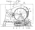
- the Drawing shows a schematic side view, partly in section, of an eyeglass lens edge grinding machine according to the invention.
- a cross slide 2 is arranged on a machine frame 1, the slide part 3 of which has guide rods 4, which are displaceably mounted in bores 5 of lugs 6 of the slide part 7 radially to an eyeglass holding shaft 14 with a spectacle lens blank 25 held thereof and to be ground.
- the slide part 7 is arranged via guide rails 8 to the machine frame 1 in a direction parallel to the spectacle lens holding shaft 14 and a shaft 10 for a pre-grinding wheel 1 and a finish and / or facet grinding wheel 12 arranged coaxially therewith.
- the shaft 10 is supported on the slide part 3 by means of bearing supports 9.
- the grinding wheels 11, 12 and the spectacle lens blank 25 with their shafts 10, 14 are surrounded by a housing 13 which has a trough (not shown in detail below) which prevents coolant and grinding abrasion from reaching the cross slide 2.
- An angle encoder 15 is connected to the spectacle lens holding shaft 14 and is connected to a computer 16.
- a displacement sensor 17 is arranged on the slide part 7 and absorbs the radial displacement of the slide part 3 with respect to the spectacle lens holding shaft 14. This displacement sensor 17 is also connected to the computer 16.
- a servomotor 18 which is controlled by the computer 16 via control lines 21 and which is in drive connection with the guide rods 4 via a magnetic powder coupling 19.
- peripheral contour values for the most varied lens shapes can be entered and stored as polar coordinates and used to control the shape grinding of the lens 25.
- a generally circular spectacle lens blank 25 is clamped into the spectacle lens holding shaft 14 and brought into contact with the pre-grinding disk 11.
- the grinding pressure that occurs arises from the torque of the magnetic powder clutch 19, which is generated by the computer 16 by applying a voltage corresponding to the torque to be set to the magnetic powder clutch 19.
- the spectacle lens holding shaft 14 with the spectacle lens blank 25 clamped therein is set in rotation in a known manner, the rotation speed usually being at 10 to 13 rpm.
- the angle encoder 15 transmits the computer 16 at equal angular intervals, for. B. in increments of 6 °, a pulse, which causes the computer 16, the associated radius to be ground the circumferential contour 24 via the servomotor 18th adjust.
- the slide part 7 and thus the grinding wheel 11 are set into an oscillating movement parallel to the axis of rotation of the spectacle lens blank 25, which is reversed in the opposite direction at the edge of the pre-grinding wheel 11. This movement is controlled by a drive, not shown, for the slide part 7, which is also connected to the computer 16.
- the reversal can be triggered by a transducer 26 arranged in the housing 13 and connected to the computer 16, this transducer 26 simultaneously measuring the width of the edge of the lens blank 25 opposite it or the contour of the lens 24.
- the computer 16 Since the computer 16 has radius values r of the point of the spectacle lens 24 touching the grinding wheel or results from the data of the displacement sensor 17, the computer 16 can be programmed so that it gives a control signal to the magnetic powder coupling 19 which shows the grinding pressure as a function of The radius r of the spectacle lens 24 touching the grinding wheel is changed in the sense of an enlargement from a large radius r to a smaller radius r.
- the grinding pressure can be changed from a minimum value of approximately 30 N with a lens radius of 40 mm to a maximum value of approximately 60 N with a radius of the lens of approximately 8 mm.
- the point of contact of the shape-ground spectacle lens 24 on the grinding wheel 11, 12 with the radius r shifts from the straight line connecting the spectacle lens holding shaft 14 and the shaft 10 to form the angle ⁇
- the line of action of the result of the grinding pressure on the spectacle lens also changes 24 attacking peripheral force and thus the torque exerted on the lens 24.
- the angle ⁇ of the instantaneous contact point of the spectacle lens 24 on the grinding wheel 11, 12 is opposite to the straight line connecting the axes of rotation of the spectacle lens holding shaft 14 and the grinding wheel shaft 10 in the sense of an increase in the grinding pressure is taken into account with the angle ⁇ increasing the direction of rotation.
- edge width of the spectacle lens 24 in the area of the contact point on the grinding wheel 11, 12 can be taken into account in the sense of an increase in the grinding pressure as the edge width increases and as the edge width becomes smaller, when the respective edge width is measured by means of the measurement sensor 26 and to the Computer 16 is directed.
- the processing speed can be optimized and adapted to the lens to be shaped, depending on whether it is a minus lens or a plus lens and whether the lens is has an additional cylindrical or prismatic cut.
- the processing speed can possibly be increased further if an oscillating component with an amplitude that can be around 20% of the grinding pressure is superimposed on the current grinding pressure.
- the frequency of the oscillating component can be around 50 s -1 .
- the grinding pressure during the shape grinding of the spectacle lens blank 25 on the pre-grinding wheel 11 is set differently than the grinding pressure during the subsequent fine or facet grinding on the fine grinding wheel 12, namely to a smaller grinding pressure during fine or facet grinding, in order to carry out this fine machining step to get the most accurate and smooth surface possible.
- This changeover of the grinding pressure takes place automatically and computer-controlled when the shape-ground spectacle lens 24 is moved from the pre-grinding wheel 11 to the fine or facet grinding wheel 12.
- a magnetic powder clutch 19 is arranged between the servomotor 18 and the drive for the slide part 3, since the transmissible torque can be adjusted particularly sensitively by means of a magnetic powder clutch.
Landscapes
- Engineering & Computer Science (AREA)
- Mechanical Engineering (AREA)
- Chemical & Material Sciences (AREA)
- Ceramic Engineering (AREA)
- Inorganic Chemistry (AREA)
- Grinding And Polishing Of Tertiary Curved Surfaces And Surfaces With Complex Shapes (AREA)
Applications Claiming Priority (2)
| Application Number | Priority Date | Filing Date | Title |
|---|---|---|---|
| DE19616536 | 1996-04-25 | ||
| DE19616536A DE19616536C2 (de) | 1996-04-25 | 1996-04-25 | Verfahren und Brillenglasrandschleifmaschine zum Formschleifen des Umfangsrandes von Brillengläsern und ggf. zum anschließenden Facettenschleifen |
Publications (3)
| Publication Number | Publication Date |
|---|---|
| EP0803325A2 true EP0803325A2 (fr) | 1997-10-29 |
| EP0803325A3 EP0803325A3 (fr) | 1998-01-14 |
| EP0803325B1 EP0803325B1 (fr) | 2002-12-18 |
Family
ID=7792422
Family Applications (1)
| Application Number | Title | Priority Date | Filing Date |
|---|---|---|---|
| EP97106143A Expired - Lifetime EP0803325B1 (fr) | 1996-04-25 | 1997-04-15 | Procédé pour le meulage façonné du bord de circonférence de verres de lunettes et le cas échéant meulage de facette suivant ainsi que dispositif de meulage pour les bords de verres de lunettes |
Country Status (4)
| Country | Link |
|---|---|
| US (1) | US5993294A (fr) |
| EP (1) | EP0803325B1 (fr) |
| DE (2) | DE19616536C2 (fr) |
| ES (1) | ES2188814T3 (fr) |
Cited By (1)
| Publication number | Priority date | Publication date | Assignee | Title |
|---|---|---|---|---|
| EP0839604A1 (fr) * | 1996-10-31 | 1998-05-06 | Nidek Co., Ltd. | Procédé et dispositif de meulage de verres de lunettes |
Families Citing this family (11)
| Publication number | Priority date | Publication date | Assignee | Title |
|---|---|---|---|---|
| JP3730410B2 (ja) * | 1998-05-29 | 2006-01-05 | 株式会社ニデック | 眼鏡レンズ加工装置 |
| JP3778707B2 (ja) * | 1998-09-29 | 2006-05-24 | 株式会社ニデック | 眼鏡レンズ加工装置 |
| DE19914174A1 (de) * | 1999-03-29 | 2000-10-12 | Wernicke & Co Gmbh | Verfahren und Vorrichtung zum Formbearbeiten des Umfangsrandes von Brillengläsern |
| SE9904705D0 (sv) | 1999-12-21 | 1999-12-21 | Astra Ab | An inhalation device |
| JP2003340698A (ja) * | 2002-05-30 | 2003-12-02 | Hoya Corp | レンズ加工装置及びレンズ加工方法 |
| EP1445065A1 (fr) * | 2003-02-05 | 2004-08-11 | Nidek Co., Ltd. | Appareil pour le traitement de lentilles ophtalmiques |
| DE10324146B4 (de) * | 2003-05-26 | 2008-08-14 | Weco Optik Gmbh | Verfahren und Vorrichtung zum Formbearbeiten von Brillengläsern |
| US7116486B2 (en) * | 2003-09-10 | 2006-10-03 | Precision Optics Corporation, Inc. | Cylindrical optical devices and method of manufacture |
| US7715105B2 (en) * | 2003-09-10 | 2010-05-11 | Precision Optics Corporation | Acylindrical optical device |
| DE102005007523A1 (de) * | 2005-02-17 | 2006-08-24 | Weco Optik Gmbh | Brillenglasrandschleifmaschine |
| KR101584265B1 (ko) * | 2010-01-29 | 2016-01-11 | 유겐가이샤 코지마 엔지니어링 | 접시형 숫돌을 이용한 렌즈 구면의 연삭 가공 방법 |
Family Cites Families (13)
| Publication number | Priority date | Publication date | Assignee | Title |
|---|---|---|---|---|
| US3590532A (en) * | 1968-03-06 | 1971-07-06 | Lawrence Littlefield | Lens finishing and modifying machine |
| US3798844A (en) * | 1972-04-24 | 1974-03-26 | Rigel Mfg Inc | Lens grinding apparatus |
| DE2332001C3 (de) * | 1972-06-28 | 1980-07-10 | Robert Raymond Maurice Asselin | Randschleifmaschine für Brillengläser |
| US4217736A (en) * | 1973-10-11 | 1980-08-19 | Kabushiki Kaisha Hoya Lens | Method for automatically grinding lenses |
| DE3221713A1 (de) * | 1982-06-09 | 1983-12-15 | Wernicke & Co GmbH, 4000 Düsseldorf | Brillenglasrandschleifmaschine |
| DE3316619A1 (de) * | 1983-05-06 | 1984-11-08 | Otto 4010 Hilden Helbrecht | Schleifmaschine fuer die raender von brillenglaesern |
| JPS60150957A (ja) * | 1984-01-14 | 1985-08-08 | Koken:Kk | レンズ加工機 |
| JPH0796185B2 (ja) * | 1988-03-18 | 1995-10-18 | 株式会社トプコン | 玉摺機砥石へのレンズ定圧当接装置 |
| JPH07100288B2 (ja) * | 1989-01-18 | 1995-11-01 | 株式会社トプコン | レンズ研削方法及びそのための装置 |
| US5022187A (en) * | 1989-09-27 | 1991-06-11 | Briot International | Device for regulating the grinding weight for an ophthalmic glass grinding machine |
| US5148637A (en) * | 1990-02-27 | 1992-09-22 | Bausch & Lomb Incorporated | Lens edging system with programmable feed and speed control |
| JP3011526B2 (ja) * | 1992-02-04 | 2000-02-21 | 株式会社ニデック | レンズ周縁加工機及びレンズ周縁加工方法 |
| DE4320934C2 (de) * | 1993-06-24 | 1995-04-20 | Wernicke & Co Gmbh | Brillenglasrandschleifmaschine |
-
1996
- 1996-04-25 DE DE19616536A patent/DE19616536C2/de not_active Expired - Fee Related
-
1997
- 1997-04-15 DE DE59708973T patent/DE59708973D1/de not_active Expired - Fee Related
- 1997-04-15 EP EP97106143A patent/EP0803325B1/fr not_active Expired - Lifetime
- 1997-04-15 ES ES97106143T patent/ES2188814T3/es not_active Expired - Lifetime
- 1997-04-25 US US08/846,133 patent/US5993294A/en not_active Expired - Fee Related
Cited By (2)
| Publication number | Priority date | Publication date | Assignee | Title |
|---|---|---|---|---|
| EP0839604A1 (fr) * | 1996-10-31 | 1998-05-06 | Nidek Co., Ltd. | Procédé et dispositif de meulage de verres de lunettes |
| US6123604A (en) * | 1996-10-31 | 2000-09-26 | Nidek Co., Ltd. | Apparatus and method for grinding eyeglass lenses |
Also Published As
| Publication number | Publication date |
|---|---|
| EP0803325A3 (fr) | 1998-01-14 |
| EP0803325B1 (fr) | 2002-12-18 |
| DE59708973D1 (de) | 2003-01-30 |
| DE19616536C2 (de) | 2000-01-27 |
| US5993294A (en) | 1999-11-30 |
| DE19616536A1 (de) | 1997-11-06 |
| ES2188814T3 (es) | 2003-07-01 |
Similar Documents
| Publication | Publication Date | Title |
|---|---|---|
| DE4320934C2 (de) | Brillenglasrandschleifmaschine | |
| DE69009890T2 (de) | Verfahren und einrichtung zum feinbearbeiten und supfinieren. | |
| DE3438238C2 (fr) | ||
| DE3435313C2 (de) | Vorrichtung zum Außenrundschleifen | |
| EP2837464B1 (fr) | Procédé de polissage destiné au traitement d'une surface optique d'une lentille optique et outils de polissage appropriés | |
| DE19616536C2 (de) | Verfahren und Brillenglasrandschleifmaschine zum Formschleifen des Umfangsrandes von Brillengläsern und ggf. zum anschließenden Facettenschleifen | |
| DE1752002A1 (de) | Verfahren und Vorrichtung zur Herstellung von Linsen | |
| DE102021104755B4 (de) | Steuerung der kontaktkraft bei einem maschinenwerkzeug | |
| DE102015115078A1 (de) | Poliervorrichtung zum Polieren konkaver Linsenflächen von optischen Linsen und Verfahren zu deren Betrieb | |
| DE4012660C2 (fr) | ||
| EP1173305B1 (fr) | Procede et dispositif permettant de fa onner le bord des verres de lunettes | |
| EP1226793A2 (fr) | Méthode pour la détermination de données de positionnement actuelles, ainsi que dispositif associé | |
| EP2852472B1 (fr) | Procédé de polissage de pièces, notamment de polissage avec centrage de pièces telles que des lentilles optiques | |
| DE19632340C2 (de) | Verfahren zum Formschleifen des Umfangsrandes von Brillengläsern und zum ggf. anschließenden Facettenschleifen | |
| EP3106262B1 (fr) | Dispositif de polissage destine a polir des surfaces de lentilles optiques et son procede de fonctionnement | |
| DE4012658C2 (de) | Brillenglasrandschleifmaschine | |
| WO2001070461A1 (fr) | Outil de meulage complementaire d'une machine de meulage de bord de verres de lunettes | |
| DE10324146B4 (de) | Verfahren und Vorrichtung zum Formbearbeiten von Brillengläsern | |
| DE102004014335A1 (de) | Vorrichtung zur Bearbeitung von Werkstücken mit gekrümmter Oberfläche | |
| DE102005007523A1 (de) | Brillenglasrandschleifmaschine | |
| DD232863A5 (de) | Verfahren und vorrichtung vom hochgeschwindigkeits-profilschleifen von rotationssymmetrischen werkstuecken | |
| DE3529876A1 (de) | Verfahren zum veraendern der position der schneide eines drehmeissels und vorrichtungen zum anwenden des erfindungsgemaessen verfahrens | |
| EP0745017B1 (fr) | Procede d'usinage du bord de verres de lunettes | |
| DE10123570A1 (de) | Schleifvorrichtung zum Bearbeiten von freien Konturen | |
| DE2252658A1 (de) | Spindelhalterung |
Legal Events
| Date | Code | Title | Description |
|---|---|---|---|
| PUAI | Public reference made under article 153(3) epc to a published international application that has entered the european phase |
Free format text: ORIGINAL CODE: 0009012 |
|
| AK | Designated contracting states |
Kind code of ref document: A2 Designated state(s): DE ES FR GB |
|
| PUAL | Search report despatched |
Free format text: ORIGINAL CODE: 0009013 |
|
| AK | Designated contracting states |
Kind code of ref document: A3 Designated state(s): DE ES FR GB |
|
| 17P | Request for examination filed |
Effective date: 19980318 |
|
| 17Q | First examination report despatched |
Effective date: 20000331 |
|
| GRAG | Despatch of communication of intention to grant |
Free format text: ORIGINAL CODE: EPIDOS AGRA |
|
| GRAG | Despatch of communication of intention to grant |
Free format text: ORIGINAL CODE: EPIDOS AGRA |
|
| GRAH | Despatch of communication of intention to grant a patent |
Free format text: ORIGINAL CODE: EPIDOS IGRA |
|
| GRAH | Despatch of communication of intention to grant a patent |
Free format text: ORIGINAL CODE: EPIDOS IGRA |
|
| GRAA | (expected) grant |
Free format text: ORIGINAL CODE: 0009210 |
|
| AK | Designated contracting states |
Kind code of ref document: B1 Designated state(s): DE ES FR GB |
|
| PG25 | Lapsed in a contracting state [announced via postgrant information from national office to epo] |
Ref country code: GB Free format text: LAPSE BECAUSE OF FAILURE TO SUBMIT A TRANSLATION OF THE DESCRIPTION OR TO PAY THE FEE WITHIN THE PRESCRIBED TIME-LIMIT Effective date: 20021218 |
|
| REG | Reference to a national code |
Ref country code: GB Ref legal event code: FG4D Free format text: NOT ENGLISH |
|
| REF | Corresponds to: |
Ref document number: 59708973 Country of ref document: DE Date of ref document: 20030130 Kind code of ref document: P Ref document number: 59708973 Country of ref document: DE Date of ref document: 20030130 |
|
| GBV | Gb: ep patent (uk) treated as always having been void in accordance with gb section 77(7)/1977 [no translation filed] |
Effective date: 20021218 |
|
| REG | Reference to a national code |
Ref country code: ES Ref legal event code: FG2A Ref document number: 2188814 Country of ref document: ES Kind code of ref document: T3 |
|
| ET | Fr: translation filed | ||
| PLBE | No opposition filed within time limit |
Free format text: ORIGINAL CODE: 0009261 |
|
| STAA | Information on the status of an ep patent application or granted ep patent |
Free format text: STATUS: NO OPPOSITION FILED WITHIN TIME LIMIT |
|
| 26N | No opposition filed |
Effective date: 20030919 |
|
| PGFP | Annual fee paid to national office [announced via postgrant information from national office to epo] |
Ref country code: ES Payment date: 20080424 Year of fee payment: 12 Ref country code: DE Payment date: 20080430 Year of fee payment: 12 |
|
| PGFP | Annual fee paid to national office [announced via postgrant information from national office to epo] |
Ref country code: FR Payment date: 20080418 Year of fee payment: 12 |
|
| REG | Reference to a national code |
Ref country code: FR Ref legal event code: ST Effective date: 20091231 |
|
| PG25 | Lapsed in a contracting state [announced via postgrant information from national office to epo] |
Ref country code: DE Free format text: LAPSE BECAUSE OF NON-PAYMENT OF DUE FEES Effective date: 20091103 |
|
| PG25 | Lapsed in a contracting state [announced via postgrant information from national office to epo] |
Ref country code: FR Free format text: LAPSE BECAUSE OF NON-PAYMENT OF DUE FEES Effective date: 20091222 |
|
| REG | Reference to a national code |
Ref country code: ES Ref legal event code: FD2A Effective date: 20090416 |
|
| PG25 | Lapsed in a contracting state [announced via postgrant information from national office to epo] |
Ref country code: ES Free format text: LAPSE BECAUSE OF NON-PAYMENT OF DUE FEES Effective date: 20090416 |