EP0803460A2 - Dispositif pour placer une bande de feuilles dans des plis en forme de Z - Google Patents
Dispositif pour placer une bande de feuilles dans des plis en forme de Z Download PDFInfo
- Publication number
- EP0803460A2 EP0803460A2 EP97103673A EP97103673A EP0803460A2 EP 0803460 A2 EP0803460 A2 EP 0803460A2 EP 97103673 A EP97103673 A EP 97103673A EP 97103673 A EP97103673 A EP 97103673A EP 0803460 A2 EP0803460 A2 EP 0803460A2
- Authority
- EP
- European Patent Office
- Prior art keywords
- belt conveyor
- suction belt
- conveyor
- conveying
- suction
- Prior art date
- Legal status (The legal status is an assumption and is not a legal conclusion. Google has not performed a legal analysis and makes no representation as to the accuracy of the status listed.)
- Withdrawn
Links
Images

Classifications
-
- B—PERFORMING OPERATIONS; TRANSPORTING
- B65—CONVEYING; PACKING; STORING; HANDLING THIN OR FILAMENTARY MATERIAL
- B65H—HANDLING THIN OR FILAMENTARY MATERIAL, e.g. SHEETS, WEBS, CABLES
- B65H45/00—Folding thin material
- B65H45/12—Folding articles or webs with application of pressure to define or form crease lines
- B65H45/18—Oscillating or reciprocating blade folders
-
- B—PERFORMING OPERATIONS; TRANSPORTING
- B31—MAKING ARTICLES OF PAPER, CARDBOARD OR MATERIAL WORKED IN A MANNER ANALOGOUS TO PAPER; WORKING PAPER, CARDBOARD OR MATERIAL WORKED IN A MANNER ANALOGOUS TO PAPER
- B31B—MAKING CONTAINERS OF PAPER, CARDBOARD OR MATERIAL WORKED IN A MANNER ANALOGOUS TO PAPER
- B31B70/00—Making flexible containers, e.g. envelopes or bags
- B31B70/26—Folding sheets, blanks or webs
- B31B70/261—Folding sheets, blanks or webs involving transversely folding, i.e. along a line perpendicular to the direction of movement
-
- B—PERFORMING OPERATIONS; TRANSPORTING
- B31—MAKING ARTICLES OF PAPER, CARDBOARD OR MATERIAL WORKED IN A MANNER ANALOGOUS TO PAPER; WORKING PAPER, CARDBOARD OR MATERIAL WORKED IN A MANNER ANALOGOUS TO PAPER
- B31B—MAKING CONTAINERS OF PAPER, CARDBOARD OR MATERIAL WORKED IN A MANNER ANALOGOUS TO PAPER
- B31B70/00—Making flexible containers, e.g. envelopes or bags
- B31B70/26—Folding sheets, blanks or webs
- B31B70/52—Folding sheets, blanks or webs by reciprocating or oscillating members other than plungers and dies, e.g. by fingers
-
- B—PERFORMING OPERATIONS; TRANSPORTING
- B31—MAKING ARTICLES OF PAPER, CARDBOARD OR MATERIAL WORKED IN A MANNER ANALOGOUS TO PAPER; WORKING PAPER, CARDBOARD OR MATERIAL WORKED IN A MANNER ANALOGOUS TO PAPER
- B31B—MAKING CONTAINERS OF PAPER, CARDBOARD OR MATERIAL WORKED IN A MANNER ANALOGOUS TO PAPER
- B31B2155/00—Flexible containers made from webs
- B31B2155/003—Flexible containers made from webs starting from tubular webs
-
- B—PERFORMING OPERATIONS; TRANSPORTING
- B31—MAKING ARTICLES OF PAPER, CARDBOARD OR MATERIAL WORKED IN A MANNER ANALOGOUS TO PAPER; WORKING PAPER, CARDBOARD OR MATERIAL WORKED IN A MANNER ANALOGOUS TO PAPER
- B31B—MAKING CONTAINERS OF PAPER, CARDBOARD OR MATERIAL WORKED IN A MANNER ANALOGOUS TO PAPER
- B31B2170/00—Construction of flexible containers
- B31B2170/20—Construction of flexible containers having multi-layered walls, e.g. laminated or lined
-
- B—PERFORMING OPERATIONS; TRANSPORTING
- B31—MAKING ARTICLES OF PAPER, CARDBOARD OR MATERIAL WORKED IN A MANNER ANALOGOUS TO PAPER; WORKING PAPER, CARDBOARD OR MATERIAL WORKED IN A MANNER ANALOGOUS TO PAPER
- B31B—MAKING CONTAINERS OF PAPER, CARDBOARD OR MATERIAL WORKED IN A MANNER ANALOGOUS TO PAPER
- B31B70/00—Making flexible containers, e.g. envelopes or bags
- B31B70/02—Feeding or positioning sheets, blanks or webs
- B31B70/10—Feeding or positioning webs
-
- B—PERFORMING OPERATIONS; TRANSPORTING
- B65—CONVEYING; PACKING; STORING; HANDLING THIN OR FILAMENTARY MATERIAL
- B65H—HANDLING THIN OR FILAMENTARY MATERIAL, e.g. SHEETS, WEBS, CABLES
- B65H2404/00—Parts for transporting or guiding the handled material
- B65H2404/20—Belts
- B65H2404/26—Particular arrangement of belt, or belts
- B65H2404/261—Arrangement of belts, or belt(s) / roller(s) facing each other for forming a transport nip
-
- B—PERFORMING OPERATIONS; TRANSPORTING
- B65—CONVEYING; PACKING; STORING; HANDLING THIN OR FILAMENTARY MATERIAL
- B65H—HANDLING THIN OR FILAMENTARY MATERIAL, e.g. SHEETS, WEBS, CABLES
- B65H2701/00—Handled material; Storage means
- B65H2701/10—Handled articles or webs
- B65H2701/11—Dimensional aspect of article or web
- B65H2701/112—Section geometry
- B65H2701/1123—Folded article or web
- B65H2701/11232—Z-folded
Definitions
- the invention relates to a device for laying a film web, preferably a tubular film web, in Z-shaped folds, with a first suction belt conveyor conveying at a higher speed and a second clamping conveyor device conveying at a lower speed, preferably a double belt conveyor, the conveying planes of which intersect and from which one another the suction belt conveyor extends beyond the feed gap of the second conveyor device and with a slide which passes through the feed plane of the suction belt conveyor and can be extended to the region of the feed gap of the second conveyor device.
- a device of this type with which a tubular film web for producing so-called pocket sacks in Z-shaped folds can be placed, is known from DE-PS 23 23 433.
- this known device however, especially when it is operated at a higher speed, there is the problem that the tubular film web is fed through the suction belt conveyor at a higher speed than it is drawn off by the double belt conveyor during the formation of folds.
- the suction box of the suction belt conveyor there is therefore a constant supply of the tubular film web at a higher speed and its peeling at a lower speed, so that, particularly when the device is operated at high cycle rates, folds fold in due to the superimposition of the supply speed with the take-off speed of the Can form tubular film web.
- the object of the invention is therefore to improve a device of the type mentioned at the outset in such a way that a film web can be folded and wrinkle-free in Z-shaped folds.
- the rod or the roller is extended approximately parallel to the conveying run of the suction belt conveyor in order to promote a good formation of the loop and to avoid wrinkling by pulling out the film web to form the loop.
- the extension speed of the rod or roller is chosen so that the loop is pulled out approximately at the point of reversal of the roller or rod and is formed in the desired manner.
- the conveying speed of the suction belt conveyor is reduced approximately to a standstill, so that the web material is merely peeled off from the substantially stationary suction belt conveyor by the double belt conveyor, and without further impairment during this peeling process Web material is fed.
- the excess web length is stored in a conventional web memory while the speed or the stoppage of the suction belt conveyor is reduced.
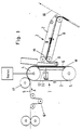
- the tubular film web is fed, for example, from the unwinder in the direction of arrow A to the suction belt conveyor 1.
- the suction belt conveyor 1 consists essentially of the divided narrow and spaced apart conveyor belts 3 running around the deflection rollers 4 and 5, of which the deflection roller 4 is driven, which are provided with rows of holes. Between the deflection rollers 4, 5, the perforated narrow conveyor belts are guided on strips 6 which have gap-shaped suction nozzles 18 on their sides facing the conveyor belts.
- the holes arranged in the conveyor belts run over the slit-shaped suction nozzles 18, so that a suction effect occurs on the upper side thereof, while the suction gaps are otherwise covered by the conveyor belts.
- the suction gaps are expediently so long that they simultaneously cover several holes in the conveyor belts.
- the slider 12 consisting of a comb-like folding knife engages, which is released from the pneumatic cylinder in the machine cycle 11 is operated.
- a pressure roller 17 is provided above the inlet-side deflection roller 4, which ensures the clean feeding of the tubular film web S.
- the second conveyor 2 consists of a double belt conveyor with the conveyor belts 7, 8, which feeds the tubular film web S laid in Z-shaped folds to the paper web 10, on which it is deposited and fixed in a known manner.
- the conveying planes of the suction belt conveyor 1 and the double belt conveyor 2 run at an angle to one another.
- the suction belt conveyor 1 rotates at a higher conveying speed than the double belt conveyor 2, so that the loop 9 corresponding to the Z-fold length is formed, as can be seen from FIG. 1.
- the U-shaped loop 9 adheres to the conveyor belts 3 with its leg lying on the suction belt conveyor 1 by the suction effect.
- the comb-shaped folding knife 12 is extended by the pneumatic cylinder 11, which detaches the upper edge of the loop 9 from the conveyor belts 3 in the manner shown in FIG. 2 and pushes the folding edge 13 thus formed into the inlet gap 19 of the double belt conveyor 2 .
- the lower part of the loop 9 still adheres to the suction belts 3, so that the loop remains stretched and a clean insertion of the Z-shaped fold is ensured.
- the tubular film web laid in Z-shaped folds is then conveyed in the direction of the arrows B. Since the loop 9 is formed not by the action of gravity but by adhering to the suction belts 3, the conveying devices 1, 2 can also be assigned to one another in a manner other than that shown.
- the device described above corresponds to the device known from DE-PS 23 23 433.
- the known device has been modified in that a pneumatic cylinder 20 is pivotally mounted in the machine frame, the piston rod 21 of which carries at its free end a roller 22 which presses the tubular film web against the suction belts 3 after each fold and at such a high speed is extended that after inserting the front folding edge through the comb-like folding knife 12 into the inlet gap of the double belt conveyor 2 and the consequent pulling off part of the tubular film web from the suction belts, the trailing section of the tubular film web is again well attached to the suction belts 3 and to the next Z -shaped fold formation the loop 9 is pulled out cleanly.
- the deflection roller 4 of the suction belt conveyor 1 is intermittently operated by a servo motor 23 driven.
- the servo motor or servo drive 23 is controlled in such a way that the suction belt conveyor 1 is almost or completely stationary during the retraction of the roller 22.
- the excess length of the web is stored in a conventional web storage device 24, which consists of deflection rollers and a pendulum roller.
- the intermittent drive of the suction belt conveyor 1 is matched to the feed rate of the tubular film in such a way that the web store 24 is emptied again after the insertion of each Z-shaped fold.
Landscapes
- Folding Of Thin Sheet-Like Materials, Special Discharging Devices, And Others (AREA)
- Advancing Webs (AREA)
- Auxiliary Devices For And Details Of Packaging Control (AREA)
Applications Claiming Priority (2)
| Application Number | Priority Date | Filing Date | Title |
|---|---|---|---|
| DE19612955A DE19612955C1 (de) | 1996-04-01 | 1996-04-01 | Vorrichtung zum Legen einer Folienbahn in Z-förmige Falten |
| DE19612955 | 1996-04-01 |
Publications (2)
| Publication Number | Publication Date |
|---|---|
| EP0803460A2 true EP0803460A2 (fr) | 1997-10-29 |
| EP0803460A3 EP0803460A3 (fr) | 1999-04-21 |
Family
ID=7790117
Family Applications (1)
| Application Number | Title | Priority Date | Filing Date |
|---|---|---|---|
| EP97103673A Withdrawn EP0803460A3 (fr) | 1996-04-01 | 1997-03-06 | Dispositif pour placer une bande de feuilles dans des plis en forme de Z |
Country Status (2)
| Country | Link |
|---|---|
| EP (1) | EP0803460A3 (fr) |
| DE (1) | DE19612955C1 (fr) |
Cited By (1)
| Publication number | Priority date | Publication date | Assignee | Title |
|---|---|---|---|---|
| DE102006051225A1 (de) * | 2006-10-31 | 2008-05-08 | Steyer Antriebstechnik Ag | Vorrichtung und Verfahren zum Ablegen einer Materialbahn |
Families Citing this family (3)
| Publication number | Priority date | Publication date | Assignee | Title |
|---|---|---|---|---|
| DE19805320B4 (de) * | 1998-02-10 | 2006-05-18 | Windmöller & Hölscher Kg | Vorrichtung zum Legen einer Folienbahn in Z-förmige Falten |
| DE29807109U1 (de) * | 1998-04-20 | 1998-07-09 | Windmöller & Hölscher, 49525 Lengerich | Vorrichtung zur Herstellung von Einstecksäcken |
| WO2022137158A1 (fr) * | 2020-12-23 | 2022-06-30 | Dandekar Sanjay Madhav | Mécanisme pour empêcher le pliage d'un article intermédiaire dans une plieuse à couteau |
Family Cites Families (2)
| Publication number | Priority date | Publication date | Assignee | Title |
|---|---|---|---|---|
| DE3151568C2 (de) * | 1981-12-28 | 1985-09-12 | Windmöller & Hölscher, 4540 Lengerich | Vorrichtung zum Z-förmigen Falten von Schlauch- oder Bahnabschnitten |
| FR2644763B1 (fr) * | 1989-03-24 | 1991-07-05 | Jensen Ag Burgdorf | Unite de pliage pour produit textile sensiblement plat et souple |
-
1996
- 1996-04-01 DE DE19612955A patent/DE19612955C1/de not_active Expired - Fee Related
-
1997
- 1997-03-06 EP EP97103673A patent/EP0803460A3/fr not_active Withdrawn
Cited By (2)
| Publication number | Priority date | Publication date | Assignee | Title |
|---|---|---|---|---|
| DE102006051225A1 (de) * | 2006-10-31 | 2008-05-08 | Steyer Antriebstechnik Ag | Vorrichtung und Verfahren zum Ablegen einer Materialbahn |
| DE102006051225B4 (de) * | 2006-10-31 | 2008-09-11 | Steyer Antriebstechnik Ag | Vorrichtung und Verfahren zum Ablegen einer Materialbahn |
Also Published As
| Publication number | Publication date |
|---|---|
| EP0803460A3 (fr) | 1999-04-21 |
| DE19612955C1 (de) | 1997-06-12 |
Similar Documents
| Publication | Publication Date | Title |
|---|---|---|
| DE3040021C2 (fr) | ||
| AT394154B (de) | Vorrichtung zum abfuehren eines von einer laufenden materialbahn kontinuierlich abgetrennten randbeschnittstreifens | |
| DE2710474A1 (de) | Verfahren und vorrichtung zum ineinanderfalten von materialbahnen | |
| DE3018982A1 (de) | Verfahren zur gleichzeitigen herstellung von zwei endloszigarettenstraengen sowie vorrichtung zur durchfuehrung des verfahrens | |
| CH654554A5 (de) | Verfahren und vorrichtung zur entnahme von auf einen wickelkern aufgewickelten flaechigen erzeugnissen, vorzugsweise druckprodukten. | |
| DE3524246A1 (de) | Verfahren und vorrichtung zum zick-zack-falten endloser materialbahnen | |
| DE3941184A1 (de) | Vorrichtung zur trennung eines kontinuierlich gefoerderten stroms von geschuppt uebereinander liegenden flachen werkstuecken | |
| DE3043507A1 (de) | Verfahren und vorrichtung zum herstellen von paeckchen gefalteter und ineinandergeschossener papierblaetter | |
| DE2657789A1 (de) | Einrichtung zum einziehen einer papierbahn in den falzapparat einer rotationsdruckmaschine | |
| DE3143762A1 (de) | "papierfoerdervorrichtung fuer eine rotationsdruckpresse" | |
| DE2746670C2 (de) | Vorrichtung zum Stapeln von Beuteln | |
| EP0305956A2 (fr) | Dispositif pour emballer des barres cylindriques composées d'une pluralité de pièces discoides | |
| DE19612955C1 (de) | Vorrichtung zum Legen einer Folienbahn in Z-förmige Falten | |
| DE2856871A1 (de) | Verfahren und vorrichtung zur herstellung kontinuierlich bestickter stoffe | |
| DE1510218C3 (de) | Vorrichtung zum kontinuierlichen Entwirren und Ausrichten von textlien Rohfasern | |
| DE3520965C2 (fr) | ||
| CH663398A5 (de) | Falzapparat fuer eine rollenrotationsdruckmaschine. | |
| DE2149172A1 (de) | Verfahren und Vorrichtung zur Zerfaserung und/oder Glaettung eines Tabakblattes | |
| DE2532880A1 (de) | Vorrichtung zum stapelweisen ablegen von hintereinander gefoerderter bogen | |
| DE4314756C2 (de) | Vorrichtung zum Schuppen und Ablegen von Bogen auf einen Stapel | |
| EP2316767B1 (fr) | Dispositif et procédé de fabrication de piles de produits d'impression | |
| DE2629381B2 (de) | Verfahren zur kontinuierlichen Herstellung von Tamponrohlingen und Vorrichtung zur Durchführung des Verfahrens | |
| DE2323433C3 (de) | Vorrichtung zum Legen einer Folienbahn in Z-Falten oder zum überlappten Ablegen von Folienbahnabschnitten | |
| CH692730A5 (de) | Einrichtung zum Fälzeln oder Hinterkleben von Buchblocks. | |
| DE2323433A1 (de) | Vorrichtung zum legen einer folienbahn in z-falten und wahlweise zum ueberlappten ablegen von folienbahnabschnitten |
Legal Events
| Date | Code | Title | Description |
|---|---|---|---|
| PUAI | Public reference made under article 153(3) epc to a published international application that has entered the european phase |
Free format text: ORIGINAL CODE: 0009012 |
|
| AK | Designated contracting states |
Kind code of ref document: A2 Designated state(s): AT BE CH DE DK ES FI FR GB GR IT LI LU NL SE |
|
| PUAL | Search report despatched |
Free format text: ORIGINAL CODE: 0009013 |
|
| RHK1 | Main classification (correction) |
Ipc: B65H 45/10 |
|
| AK | Designated contracting states |
Kind code of ref document: A3 Designated state(s): AT BE CH DE DK ES FI FR GB GR IT LI LU NL SE |
|
| 17P | Request for examination filed |
Effective date: 19991021 |
|
| STAA | Information on the status of an ep patent application or granted ep patent |
Free format text: STATUS: THE APPLICATION HAS BEEN WITHDRAWN |
|
| 18W | Application withdrawn |
Withdrawal date: 20010802 |