EP0803465B1 - Installation pour détecter la charge momentanée et/ou la sollicitation de longue durée de moyens de manipulation, en particulier de dispositifs de levage - Google Patents
Installation pour détecter la charge momentanée et/ou la sollicitation de longue durée de moyens de manipulation, en particulier de dispositifs de levage Download PDFInfo
- Publication number
- EP0803465B1 EP0803465B1 EP97250125A EP97250125A EP0803465B1 EP 0803465 B1 EP0803465 B1 EP 0803465B1 EP 97250125 A EP97250125 A EP 97250125A EP 97250125 A EP97250125 A EP 97250125A EP 0803465 B1 EP0803465 B1 EP 0803465B1
- Authority
- EP
- European Patent Office
- Prior art keywords
- load
- motor
- current
- phase
- induction motor
- Prior art date
- Legal status (The legal status is an assumption and is not a legal conclusion. Google has not performed a legal analysis and makes no representation as to the accuracy of the status listed.)
- Expired - Lifetime
Links
- 238000005259 measurement Methods 0.000 claims description 20
- 238000004804 winding Methods 0.000 claims description 16
- 230000005540 biological transmission Effects 0.000 claims description 4
- 230000001133 acceleration Effects 0.000 claims description 3
- 230000005484 gravity Effects 0.000 claims description 2
- 230000001360 synchronised effect Effects 0.000 claims description 2
- 230000006698 induction Effects 0.000 claims 9
- 230000007246 mechanism Effects 0.000 claims 1
- 238000012806 monitoring device Methods 0.000 claims 1
- 238000011144 upstream manufacturing Methods 0.000 claims 1
- 238000011156 evaluation Methods 0.000 description 16
- 238000001514 detection method Methods 0.000 description 15
- 238000013461 design Methods 0.000 description 4
- 230000008901 benefit Effects 0.000 description 3
- 230000001419 dependent effect Effects 0.000 description 3
- 238000012544 monitoring process Methods 0.000 description 2
- 230000008929 regeneration Effects 0.000 description 2
- 238000011069 regeneration method Methods 0.000 description 2
- 238000006243 chemical reaction Methods 0.000 description 1
- 238000012937 correction Methods 0.000 description 1
- 230000003292 diminished effect Effects 0.000 description 1
- 238000009434 installation Methods 0.000 description 1
- 238000000034 method Methods 0.000 description 1
- 238000000819 phase cycle Methods 0.000 description 1
- 238000009420 retrofitting Methods 0.000 description 1
- 230000002441 reversible effect Effects 0.000 description 1
- 231100000817 safety factor Toxicity 0.000 description 1
- 238000010008 shearing Methods 0.000 description 1
- 230000001960 triggered effect Effects 0.000 description 1
Images
Classifications
-
- G—PHYSICS
- G07—CHECKING-DEVICES
- G07C—TIME OR ATTENDANCE REGISTERS; REGISTERING OR INDICATING THE WORKING OF MACHINES; GENERATING RANDOM NUMBERS; VOTING OR LOTTERY APPARATUS; ARRANGEMENTS, SYSTEMS OR APPARATUS FOR CHECKING NOT PROVIDED FOR ELSEWHERE
- G07C3/00—Registering or indicating the condition or the working of machines or other apparatus, other than vehicles
-
- B—PERFORMING OPERATIONS; TRANSPORTING
- B66—HOISTING; LIFTING; HAULING
- B66C—CRANES; LOAD-ENGAGING ELEMENTS OR DEVICES FOR CRANES, CAPSTANS, WINCHES, OR TACKLES
- B66C13/00—Other constructional features or details
- B66C13/16—Applications of indicating, registering, or weighing devices
-
- B—PERFORMING OPERATIONS; TRANSPORTING
- B66—HOISTING; LIFTING; HAULING
- B66D—CAPSTANS; WINCHES; TACKLES, e.g. PULLEY BLOCKS; HOISTS
- B66D1/00—Rope, cable, or chain winding mechanisms; Capstans
- B66D1/54—Safety gear
-
- H—ELECTRICITY
- H02—GENERATION; CONVERSION OR DISTRIBUTION OF ELECTRIC POWER
- H02P—CONTROL OR REGULATION OF ELECTRIC MOTORS, ELECTRIC GENERATORS OR DYNAMO-ELECTRIC CONVERTERS; CONTROLLING TRANSFORMERS, REACTORS OR CHOKE COILS
- H02P29/00—Arrangements for regulating or controlling electric motors, appropriate for both AC and DC motors
- H02P29/40—Regulating or controlling the amount of current drawn or delivered by the motor for controlling the mechanical load
Definitions
- the invention relates to a device for detecting the instantaneous load and / or the permanent loading of conveyors, in particular hoists, comprising a load measuring device and an electric motor as a drive means for the Lifting and lowering a load.
- Load measuring devices for hoists are known.
- a load measuring device for a hoist with a Hubwerksmotor described which is arranged in the support means and by means of a Switzerlandmeßstabes allows the detection of the load.
- the Switzerlandmeßstab has a Strain gauge, whose electrical resistance varies depending on the load acting on the hoist load changes, so that by detecting the Resistance of the strain gauge or a voltage drop at the Strain gauge at constant current flow proportional to the load electrical signal is generated. It allows a special bridge circuit of strain gauges and resistors a very accurate determination of the Load.
- the burden of Constantly checking the hoist and protecting the hoist from overloading by connected to the load measuring electronic Wam pleaseden which automatically switch off the hoist when the rated load is exceeded.
- DE 40 38 981 A1 discloses a hoist drive with an asynchronous motor, one feeding the motor with AC variable frequency Frequency converter and one of the frequency of the frequency converter to one in particular infinitely selectable frequency setpoint setting Control circuitry.
- the control circuit comprises a detection device which a measure of the instantaneous torque of the engine Determined load value, as well as a data store, the data for a Limit characteristic stores the relationship between the maximum permissible values Frequencies of alternating current on the one hand and load values for one on the other hand represents predetermined power of the engine.
- the control circuit sets the frequency of the frequency converter to one dependent on the frequency determining load value according to the data stored in the data memory Data resulting frequency value and leads to a change in the Load value after.
- Load measuring devices also serve to detect Load characteristics of hoists, by equivalent damages Load values based on the measured loads taking into account the Charging time determined and summed up. So is from the DE-GM 2 ° 95 03 416 U1 a device for determining the dynamic load of Components, systems and machines are known in the monitoring of the System load load values over several load changes formed and accumulated in a memory are stored. Exceeding the accumulated total load value is triggered by triggering a corresponding Alarm signal displayed; In this way it is possible a regeneration and / or an exchange of the hoist, for example, according to the relevant neither too early nor too late, and thus the Optimum use of hoist with regard to service life.
- the disadvantage here is the relatively large effort required to capture the total load and for monitoring a predetermined lifetime limit is required.
- the object of the invention is therefore to provide a device for detecting the current load and / or the duration of use of subsidies for Hoists create no changes or fixtures in load-bearing parts a hoist or structure require and still a very accurate measurement enable. In addition, it should allow this detection device, the accumulated permanent load on the hoist with sufficient accuracy technically very simple way to determine.
- the invention provides that the electric motor as a three-phase asynchronous motor is formed by the load measuring the active power of the Three-phase asynchronous motor can be detected by means of a current and voltage measurement and is comparable to a reference power to determine the current Load, the reference power being a calculated power of Drehstromasynchronmotors for driving a nominal load capacity of the conveyor is.
- the solution according to the invention makes it possible, without changes or installations in carrying parts of the conveyor the current load as well Continuous stress with high accuracy, especially in the field of Nominal load to be determined. So it is possible, for example, over the Active power consumption of the three-phase asynchronous motor load, in particular if this is in the range of the rated load, with a measuring error of 1 to 2% determine.
- the detection device as load control for protection the conveyor ensures the solution of the invention a perfect Detection of overload.
- the detection of the continuous load of the conveyor is with the Solution according to the invention also possible with little effort.
- the something greater measurement error in the partial load range is for the detection of continuous load over a long period of subordinate importance, especially as in the case of Continuous stress the ratio of partial load to rated load with the third Potency enters into the continuous load of the subsidy, according to the relevant provisions for determining the lifetime limit of Funding.
- the device according to the invention consequently ensures the required high accuracy, which is sufficient for a sufficiently accurate determination of Continuous loading of the conveyor is necessary.
- the current load as the ratio or difference is formed from the active power and the reference power and that a Display device for displaying the current load as load control is provided.
- a shutdown device is provided to interrupt the lifting movement by switching off the motor when the current load exceeds a predetermined load, this being must be within the permissible load values.
- the accuracy of the detection of the current heat losses can be improved if the temperature of the stator winding measurable and the electrical resistance of the Stator winding from whose cold resistance is calculated.
- the accuracy of the detection of the permanent load and / or the current Load is further improved by the measured active power consumption to the idling losses of the conveyor (so by a corresponding offset) is diminished, since these too do not contribute to the lifting of the subsidy; the idling losses can be measured by measuring the power consumption of the conveyor be determined without load.
- the switching of the direction of rotation of the Drehstromasynchronmotors in that a reversing switch for turning the Motor phase leads is provided.
- the current measurement for determining the active power consumption of the Drehstromasynchronmotors takes place in that a current transformer is provided, the the current in one of the turned for a change of direction Motor phase lead detected.
- This has the advantage that the differing Phase sequences between the measured current and the measured voltage "Lifting the load” and when “lowering the load” are distinguishable, so that the detection the permanent load and / or the current load on the basis of Active power consumption only in the relevant state "lifting the load” takes place.
- the invention proposes that the voltage measurement between the Motor phase lead whose current is detected, and one of the other two Motor phase leads takes place.
- the advantage of this measurement is that Voltage and current can only be measured simultaneously if the State "lifting the load" is switched on.
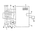
- An embodiment of the invention is schematically in the single figure illustrated, the means for detecting the current load and / or the continuous stress of a hoist with a three-phase asynchronous as Drive means shows.
- a device for detecting the permanent load and / or the current load of a three-phase asynchronous motor 1 as a drive means of a Hubtechnik shown.
- the three-phase asynchronous motor 1 is as a squirrel-cage rotor formed and via motor phase leads 2a, 2b, 2c to three-phase network phases L1, L2, L3 connected to a three-phase system.
- the motor phase feeder 2c is over a current transformer 3, through which the stator current of the asynchronous motor. 1 is measurable.
- the current transformer 3 generates a stator current proportional Tension; via lines 4, the output of the current transformer 3 with a Evaluation unit 5 connected.
- the motor phase leads 2a, 2b, 2c Connected via leads 6a, 6b, 6c to the evaluation unit 5.
- the determination of the active power consumption of the Drehstromasynchronmotors 1 based on the measured in the evaluation unit 5 Voltage and current values of the three-phase asynchronous motor 1 in per se known Way, but controlled by the evaluation unit 5 only in the state "lifting the load ", since only in this condition a clear connection between the Active power consumption and a calculable reference power of the hoist exist.
- the determined active power consumption is in the evaluation unit 5 by an offset reduced, which takes into account the idling losses of the hoist, which in essentially from magnetic reversal losses of the magnetic sheets and the Friction losses of the motor rotor of the three-phase asynchronous motor. 1 composed.
- the value of these losses is by means of a power measurement of the idle-driven three-phase asynchronous motor 1 can be easily determined or calculable on the basis of the design data and in the evaluation unit 5 in one Storage element filed.
- the active power consumption is in each case by the proportion of the current heat losses the motor stator winding corrected, the current heat losses from the measured current and the electrical resistance of the stator winding of Three-phase asynchronous motor 1 are calculated.
- electrical resistance value of Stator winding As electrical resistance value of Stator winding is used their cold resistance, which from the winding data of the three-phase asynchronous motor 1 is calculated.
- the temperature dependence of the electrical resistance of the Stator winding by detecting the winding temperature to take into account by for cold resistance a corresponding correction value (positive or negative) added becomes.
- the electrical resistance of the stator winding is also in one Memory element of the evaluation unit 5 stored.
- the evaluation unit 5 determines the instantaneous load of the hoist based on the reference power and displays the difference or the ratio of measured active power consumption and reference power;
- the reference power is therefore calculated solely from the design data of the hoist.
- the reference power is the proportion of power that the three-phase asynchronous motor. 1 removed from the three-phase network and transmits over the motor gap to the moment to generate the three-phase asynchronous motor 1 for lifting the rated load at Constant stroke speed transmits over the drive shaft.
- the reference power is calculated from the field power of the Three-phase asynchronous motor 1 at rated load and results from the rotational frequency, with the magnetic field of the stator in the air gap between the stator and rotor of the Drehstromasynchronmotors 1 rotates, and the output torque. Due to the magnetic transmission through the air gap are the field power and the delivered moment directly proportional, i. the reference performance is a measure of the Load - dependent part of the power required for lifting the rated load over the Air gap of the engine must be transferred to the rotor.
- the Load of the hoist by a momentary load clearly by comparison the stator side measured active power consumption of Three-phase asynchronous motor 1 (of the stator) with the calculated reference power be determined.
- the difference or ratio of these two benefits equal to the difference or the ratio between the momentary load and the rated load, is indicated by an in the evaluation unit 5 integrated display device 10 as a current load displayable, which serves an operator as a load control.
- a current load displayable which serves an operator as a load control.
- Control line 8 is provided, which is connected to a switch (schematically in the Figur), via which the power supply of the three-phase asynchronous motor. 1 is interrupted when the current load the predetermined allowable Exceeding load.
- the control line 8 can only be activated when the Hoist is in the "lifting the load" state.
- the line 6c is for Evaluation unit 5 is provided, which ensures that the voltage measurement between the motor phase supply line 2c, whose current is detected, and the other two Motor phase leads 2a, 2b can be measured.
- the voltage measurement takes place the non-turned motor phase feeder 2a before the reversing switch 9 and the reversible motor phase lead 2c or 2b behind the reversing switch 9 related to the potential of the motor phase feeder 2a.
- Both states are characterized in the Evaluation unit 5 distinguishable, so that only when lifting the load current and Measured voltage and from this the relevant for the current load, the Reference power corresponding active power consumption of Three-phase asynchronous motor 1 is determined.
- the Evaluation unit 5 can correctly determine due to the selected wiring, whether the hoist is in the "lifting the load” or “lowering the load” position, and thus for the detection of the current load and / or the Permanent load determine the relevant active power.
- the cheapest Detection time is the one where the load capacity with constant lifting speed is lifted; The detection therefore always takes place in the embodiment with a short time delay, so after completion of the startup, so after the start-up phase.
- the current load as instantaneous stress the conveyor over time integrable and in a designated storage unit can be stored; the accumulated permanent load, that is the one in the storage unit stored integral value can be displayed by the load indicator 7.
- the load indicator 7 it is also possible in determining continuous stress the Ratio of partial load to nominal load with the third power in the Continuous load of the conveyor to be incorporated.
- the connections for the voltage measurement are used at the same time Power supply of the evaluation unit 5.
Landscapes
- Engineering & Computer Science (AREA)
- Mechanical Engineering (AREA)
- Power Engineering (AREA)
- Physics & Mathematics (AREA)
- General Physics & Mathematics (AREA)
- Control Of Ac Motors In General (AREA)
- Control Of Electric Motors In General (AREA)
- Control And Safety Of Cranes (AREA)
- Tests Of Circuit Breakers, Generators, And Electric Motors (AREA)
- Force Measurement Appropriate To Specific Purposes (AREA)
Claims (12)
- Dispositif de mesure de la contrainte instantanée et/ou de la sollicitation de fatigue de moyens de manipulation, en particulier de treuils de levage, qui comporte un dispositif de mesure de charge et un moteur électrique (1) servant de moyens d'entraínement pour lever et abaisser une charge,
le moteur électrique étant conformé en moteur asynchrone triphasé, le dispositif de mesure de charge permettant de mesurer l'absorption de puissance active par le moteur asynchrone triphasé (1) par une mesure du courant et de la tension et de la comparer à une puissance de référence pour déterminer la contrainte instantanée, la puissance de référence étant une puissance calculée du moteur asynchrone triphasé pour entraíner une charge nominale du moyen de déplacement,
caractérisé en ce que l'absorption de puissance active mesurée est réduite des pertes par effet Joule dans l'enroulement du stator du moteur. - Dispositif selon la revendication 1, caractérisé en ce que la contrainte instantanée est formée par le rapport ou la différence entre l'absorption de puissance active et la puissance de référence et en ce qu'il est prévu un dispositif de présentation (10) destiné à présenter la contrainte instantanée sous la forme d'un contrôle de contrainte.
- Dispositif selon la revendication 1 ou 2, caractérisé en ce qu'il est prévu un dispositif d'arrêt destiné à interrompre le mouvement de levage en arrêtant le moteur asynchrone triphasé lorsque la contrainte instantanée devient supérieure à une contrainte prédéterminée.
- Dispositif selon l'une des revendications 1 à 3, caractérisé en ce que la contrainte instantanée peut être intégrée dans le temps sous la forme d'une sollicitation instantanée du moyen de manipulation et peut être stockée dans une unité de mémoire prévue sous la forme de sollicitation de fatigue et être présentée au moyen d'un dispositif de présentation de contrainte (7).
- Dispositif selon l'une des revendications 1 à 4, caractérisé en ce que la puissance de référence pour le levage vertical est déterminée à partir du couple d'entraínement du moteur asynchrone triphasé (1) pour la charge nominale et de la fréquence de rotation synchrone conformément à la suite formule suivante :
m = charge
g = gravitation
RTR = rayon du treuil
f = fréquence du réseau
i = démultiplication du réducteur
z = mouflage
p = nombre de paires de pôles
η = rendement du réducteur - Dispositif selon la revendication 1, caractérisé en ce que les pertes par effet Joule sont déterminées à partir du courant mesuré et de la résistance électrique de l'enroulement du stator du moteur asynchrone triphasé (1).
- Dispositif selon la revendication 6, caractérisé en ce que la température de l'enroulement du stator peut être mesurée et la résistance électrique de l'enroulement du stator est calculée à partir de sa résistance à froid.
- Dispositif selon l'une des revendications 1 à 7, caractérisé en ce que l'absorption de puissance active mesurée est réduite d'un décalage dû aux pertes de fonctionnement à vide du moyen de manipulation.
- Dispositif selon l'une des revendications 1 à 8, caractérisé en ce qu'il est prévu un inverseur de marche (9) destiné à inverser les lignes de phase de moteur (2b, 2c) pour changer le sens de rotation du moteur asynchrone triphasé (1).
- Dispositif selon l'une des revendications 1 à 9, caractérisé en ce qu'il est prévu un transformateur de courant pour la mesure de l'absorption de puissance active du moteur asynchrone triphasé (1), le transformateur de courant mesurant le courant dans une ligne de phase de moteur (2b ou 2c) inversée afin d'effectuer un changement de sens de rotation.
- Dispositif selon l'une des revendications 1 à 10, caractérisé en ce que la mesure de la tension est effectuée entre la ligne de phase de moteur (2b ou 2c), dont le courant est mesuré, et l'une des deux autres lignes de phase de moteur (2a ou 2c ou 2b).
- Dispositif selon l'une des revendications 1 à 11, caractérisé en ce que la mesure de la tension est effectuée entre la ligne de phase de moteur (2c), dont le courant est mesuré, et les deux autres lignes de phase de moteur (2a, 2b), la mesure de la tension de la ligne de phase de moteur non inversée (2a) étant effectuée en avant de l'inverseur de marche (9) et celle de la ligne de phase de moteur (2c ou 2b) est effectué en arrière de l'inverseur de marche (9) par référence au potentiel de la ligne de phase de moteur (2a).
Applications Claiming Priority (2)
| Application Number | Priority Date | Filing Date | Title |
|---|---|---|---|
| DE19617105A DE19617105C2 (de) | 1996-04-19 | 1996-04-19 | Einrichtung zur Erfassung der momentanen Belastung von Fördermitteln, insbesondere von Hubwerken |
| DE19617105 | 1996-04-19 |
Publications (3)
| Publication Number | Publication Date |
|---|---|
| EP0803465A2 EP0803465A2 (fr) | 1997-10-29 |
| EP0803465A3 EP0803465A3 (fr) | 2002-08-14 |
| EP0803465B1 true EP0803465B1 (fr) | 2005-03-16 |
Family
ID=7792787
Family Applications (1)
| Application Number | Title | Priority Date | Filing Date |
|---|---|---|---|
| EP97250125A Expired - Lifetime EP0803465B1 (fr) | 1996-04-19 | 1997-04-18 | Installation pour détecter la charge momentanée et/ou la sollicitation de longue durée de moyens de manipulation, en particulier de dispositifs de levage |
Country Status (4)
| Country | Link |
|---|---|
| US (1) | US5859373A (fr) |
| EP (1) | EP0803465B1 (fr) |
| JP (1) | JPH1082702A (fr) |
| DE (2) | DE19617105C2 (fr) |
Cited By (1)
| Publication number | Priority date | Publication date | Assignee | Title |
|---|---|---|---|---|
| EP4410734A1 (fr) * | 2023-01-31 | 2024-08-07 | Vollert Anlagenbau GmbH | Dispositif de levage et procédé de détermination de la distance théorique d'un câble |
Families Citing this family (25)
| Publication number | Priority date | Publication date | Assignee | Title |
|---|---|---|---|---|
| DE19802674C2 (de) * | 1998-01-24 | 2001-05-10 | Michael Ertl | Verfahren zur Gewichtsmessung von Lasten in Hubvorrichtungen |
| DE19817942A1 (de) * | 1998-04-17 | 1999-10-28 | Siemens Ag | Steuereinrichtung für einen Hochspannungsschalter und Verfahren zum Betreiben des Hochspannungsschalters |
| US6434505B1 (en) | 1999-10-15 | 2002-08-13 | Atecs Mannesmann Ag | Method for determining the instantaneous winding temperature of the stator winding of a three-phase AC motor, in particular a pole-changeable asynchronous motor |
| DE19956265B4 (de) * | 1999-11-23 | 2005-06-30 | Liebherr-Werk Ehingen Gmbh | Vorrichtung zur Überwachung des Betriebs von Hubwinden |
| JP3757745B2 (ja) * | 2000-03-30 | 2006-03-22 | ダイキン工業株式会社 | 予熱電力の制御方法及び予熱発生機構 |
| FI108717B (fi) * | 2000-08-29 | 2002-03-15 | Konecranes Global Oy | Menetelmä ja laitteisto nostimen kuorman mittaamiseksi |
| FI115966B (fi) * | 2000-08-29 | 2005-08-31 | Kci Kone Cranes Int Oy | Menetelmä ja laitteisto nostimen nostomoottorin jarrun avautumisen valvontaan |
| US6527130B2 (en) | 2001-02-16 | 2003-03-04 | General Electric Co. | Method and system for load measurement in a crane hoist |
| DE10119201A1 (de) * | 2001-04-19 | 2002-10-24 | Bsh Bosch Siemens Hausgeraete | Verfahren und Vorrichtung zum Messen der Wicklungstemperatur eines Antriebsmotors |
| DE10126733A1 (de) * | 2001-05-31 | 2002-12-05 | Wilo Gmbh | Lebensdauerüberwachung an Umwälzpumpen |
| DE102004007504B4 (de) * | 2004-02-13 | 2009-11-05 | Demag Cranes & Components Gmbh | Hebezeug, insbesondere Kettenzug oder Seilzug |
| US20090090102A1 (en) * | 2006-05-03 | 2009-04-09 | Wilfred Busse | Method of reducing the load of one or more engines in a large hydraulic excavator |
| DE102006053730C5 (de) * | 2006-11-15 | 2017-11-09 | Stabilus Gmbh | Antriebseinrichtung |
| US8491025B2 (en) | 2007-02-13 | 2013-07-23 | Edw. C. Levy Co. | Magnet controller for controlling a lifting magnet |
| EP2225569B1 (fr) * | 2007-11-26 | 2013-08-14 | SafeWorks, LLC | Capteur de puissance |
| US20110056192A1 (en) * | 2009-09-10 | 2011-03-10 | Robert Weber | Technique for controlling pumps in a hydraulic system |
| US9182270B2 (en) | 2012-05-14 | 2015-11-10 | Magnetek, Inc. | Method and apparatus for measuring a load in a material handling system |
| NL2009783C2 (nl) * | 2012-11-09 | 2014-05-12 | Pjotter B V | Werkwijze, gebruik en inrichting voor het bepalen van een veiligheidsstatus van een lier. |
| US9573789B2 (en) * | 2014-03-27 | 2017-02-21 | Thyssenkrupp Elevator Corporation | Elevator load detection system and method |
| US9802797B2 (en) * | 2014-08-15 | 2017-10-31 | Ramsey Winch Company | System and method for thermal protection of an electric winch |
| JP6274077B2 (ja) | 2014-11-04 | 2018-02-07 | 株式会社デンソー | モータ制御装置 |
| US9950908B2 (en) | 2016-03-10 | 2018-04-24 | Magnetek, Inc. | System and method for determining a load in a material handling system |
| US10457531B2 (en) * | 2016-11-30 | 2019-10-29 | Ningbo China Winch Co., Ltd. | Winch and safety device thereof |
| EP3848314B1 (fr) * | 2020-01-10 | 2023-10-04 | Inventio Ag | Système de mesure de la charge dans un système d'ascenseur ainsi que procédé de détermination de la charge d'une cabine d'ascenseur |
| DE102021102077A1 (de) | 2021-01-29 | 2022-08-04 | Movecat GmbH | Verfahren zur Ermittlung der Belastungen einer Hebe- oder Transportvorrichtung mit elektrischem Antrieb |
Family Cites Families (11)
| Publication number | Priority date | Publication date | Assignee | Title |
|---|---|---|---|---|
| DE1225832B (de) * | 1964-04-14 | 1966-09-29 | Siemens Ag | Elektrische Schutzeinrichtung gegen mechanische UEberlastung von Hebezeugen |
| US4060841A (en) * | 1976-04-19 | 1977-11-29 | Ernest Duane Allen | Motor protector for three-phase motors |
| US4106580A (en) * | 1976-10-26 | 1978-08-15 | Brookline Instrument Company | Force measuring apparatus |
| DE2823401A1 (de) * | 1978-05-29 | 1979-12-06 | Demag Ag | Lastmesseinrichtung fuer hebezeuge |
| US4423785A (en) * | 1980-03-18 | 1984-01-03 | Kabushiki Kaisha Komatsu Seisakusho | Load control device for a working tool of a construction vehicle |
| US4623041A (en) * | 1984-10-22 | 1986-11-18 | Otis Elevator Company | Elevator load measuring |
| DE3623755A1 (de) * | 1986-07-15 | 1988-02-18 | Abus Kg | Einrichtung zur ueberlastsicherung von elektrischen antrieben |
| AU621146B2 (en) * | 1988-09-08 | 1992-03-05 | Trw Steering & Industrial Products (Japan) Co., Ltd. | Apparatus and method of detecting abnormal load of pressurizing apparatus |
| US4953053A (en) * | 1989-01-31 | 1990-08-28 | Harnischfeger Corporation | Method and apparatus for detecting mechanical overload of a hoist |
| DE4038981C2 (de) * | 1990-12-06 | 1998-05-07 | Man Ghh Logistics | Hubwerksantrieb, insbesondere für einen Turmkran |
| DE29503416U1 (de) * | 1995-03-02 | 1995-07-20 | Höhn, Carsten, Dipl.-Ing, 28832 Achim | Gerät zur Ermittlung der dynamischen Beanspruchung an Bauteilen, Anlagen und Maschinen |
-
1996
- 1996-04-19 DE DE19617105A patent/DE19617105C2/de not_active Expired - Fee Related
-
1997
- 1997-04-17 US US08/840,859 patent/US5859373A/en not_active Expired - Lifetime
- 1997-04-18 JP JP9116547A patent/JPH1082702A/ja active Pending
- 1997-04-18 EP EP97250125A patent/EP0803465B1/fr not_active Expired - Lifetime
- 1997-04-18 DE DE59712225T patent/DE59712225D1/de not_active Expired - Lifetime
Cited By (1)
| Publication number | Priority date | Publication date | Assignee | Title |
|---|---|---|---|---|
| EP4410734A1 (fr) * | 2023-01-31 | 2024-08-07 | Vollert Anlagenbau GmbH | Dispositif de levage et procédé de détermination de la distance théorique d'un câble |
Also Published As
| Publication number | Publication date |
|---|---|
| DE19617105C2 (de) | 1998-07-02 |
| DE19617105A1 (de) | 1997-10-23 |
| DE59712225D1 (de) | 2005-04-21 |
| EP0803465A2 (fr) | 1997-10-29 |
| US5859373A (en) | 1999-01-12 |
| EP0803465A3 (fr) | 2002-08-14 |
| JPH1082702A (ja) | 1998-03-31 |
Similar Documents
| Publication | Publication Date | Title |
|---|---|---|
| EP0803465B1 (fr) | Installation pour détecter la charge momentanée et/ou la sollicitation de longue durée de moyens de manipulation, en particulier de dispositifs de levage | |
| EP2313792B1 (fr) | Dispositif de surveillance pour des systèmes pitch (réglage à pas variable de l'angle de calage des pales) d'éoliennes | |
| DE19645812C1 (de) | Steuerungsanordnung mit Erkennung des Gewichts der Last | |
| DE60131608T2 (de) | Verfahren und Vorrichtung zum Steueren der Bremslösung in dem Hubmotor von einer Hebevorrichtung | |
| DE2430798B2 (de) | Anordnung zur Erfassung von Erdschlüssen im Läuferkreis einer schleifringlos über umlaufende Gleichrichter erregten Synchronmaschine | |
| EP0224689B1 (fr) | Dispositif pour contrôler la température des moteurs shunt à courant continu pour presses rotatives à imprimer | |
| DE102017100881A1 (de) | Wicklungstemperaturüberwachung | |
| DE69102318T2 (de) | Verfahren und Gerät zur Bremsung eines Kurzschlussläufer-Aufzugsmotors bei Störungsfällen, gespeist von einem Frequenzwandler. | |
| EP3383789B1 (fr) | Treuil à cable passant | |
| EP1184329B1 (fr) | Procédé et dispositif pour mesurer la charge dans un appareil de levage | |
| EP1767790B1 (fr) | Système de pompe à vide | |
| EP0347408A1 (fr) | Entraînement pour dispositifs de levage ou similaire | |
| DE747055C (de) | Drehstromhub- oder Fahrwerk | |
| DE19857695C2 (de) | Verfahren und Einrichtung zur Steuerung des Auslaufes einer Induktionsmaschine | |
| DE112021006403T5 (de) | Oberer-und-Unterer-Grenzwert-Erfassungsgerät und Verfahren für einen elektrischen Kettenzug | |
| EP0988689B1 (fr) | Moteur a reluctance | |
| EP3676954B1 (fr) | Entraînement à commande de charge dynamique intégrée | |
| DE102007053755A1 (de) | Verfahren und Einrichtung zur Überwachung einer Läufertemperatur einer permanent erregten elektrischen Maschine | |
| DE1906383B2 (de) | Einrichtung zur Drehzahlregelung von Drehstrom-Schleifringläufermotoren für Kranhub- oder Fahrwerke | |
| DE1901389B2 (de) | Vorrichtung zum dauernden Straffhalten einer Leine | |
| DE2446111C3 (de) | Einrichtung zum Schutz von elektrischen Drehfeldmaschinen gegen Überlastung durch Inversströme | |
| DE1037096B (de) | Steuereinrichtung fuer einen von einer Mehrphasenstromquelle gespeisten Mehrphasen-Wechselstrommotor fuer den Senkbetrieb von Kranen, Aufzuegen od. dgl. | |
| DE102020116644A1 (de) | Blockadeerkennung | |
| EP0227721A1 (fr) | Procede et dispositif de reduction des pertes d'un moteur a induction dans le fer et dans le cuivre | |
| DE1431870A1 (de) | Automatische UEberlastungs-Schutzeinrichtung,insbesondere fuer Krane |
Legal Events
| Date | Code | Title | Description |
|---|---|---|---|
| PUAI | Public reference made under article 153(3) epc to a published international application that has entered the european phase |
Free format text: ORIGINAL CODE: 0009012 |
|
| AK | Designated contracting states |
Kind code of ref document: A2 Designated state(s): DE FR GB IT |
|
| PUAL | Search report despatched |
Free format text: ORIGINAL CODE: 0009013 |
|
| AK | Designated contracting states |
Kind code of ref document: A3 Designated state(s): DE FR GB IT |
|
| RIC1 | Information provided on ipc code assigned before grant |
Free format text: 7B 66C 15/00 A, 7H 02H 7/085 B, 7B 66C 13/16 B, 7B 66D 1/54 B, 7G 07C 3/00 B |
|
| 17P | Request for examination filed |
Effective date: 20021126 |
|
| 17Q | First examination report despatched |
Effective date: 20031205 |
|
| RAP1 | Party data changed (applicant data changed or rights of an application transferred) |
Owner name: DEMAG CRANES & COMPONENTS GMBH |
|
| GRAP | Despatch of communication of intention to grant a patent |
Free format text: ORIGINAL CODE: EPIDOSNIGR1 |
|
| GRAS | Grant fee paid |
Free format text: ORIGINAL CODE: EPIDOSNIGR3 |
|
| GRAA | (expected) grant |
Free format text: ORIGINAL CODE: 0009210 |
|
| AK | Designated contracting states |
Kind code of ref document: B1 Designated state(s): DE FR GB IT |
|
| REG | Reference to a national code |
Ref country code: GB Ref legal event code: FG4D Free format text: NOT ENGLISH |
|
| REF | Corresponds to: |
Ref document number: 59712225 Country of ref document: DE Date of ref document: 20050421 Kind code of ref document: P |
|
| GBT | Gb: translation of ep patent filed (gb section 77(6)(a)/1977) |
Effective date: 20050520 |
|
| ET | Fr: translation filed | ||
| PLBE | No opposition filed within time limit |
Free format text: ORIGINAL CODE: 0009261 |
|
| STAA | Information on the status of an ep patent application or granted ep patent |
Free format text: STATUS: NO OPPOSITION FILED WITHIN TIME LIMIT |
|
| 26N | No opposition filed |
Effective date: 20051219 |
|
| PGFP | Annual fee paid to national office [announced via postgrant information from national office to epo] |
Ref country code: FR Payment date: 20110510 Year of fee payment: 15 |
|
| PGFP | Annual fee paid to national office [announced via postgrant information from national office to epo] |
Ref country code: GB Payment date: 20110421 Year of fee payment: 15 |
|
| PGFP | Annual fee paid to national office [announced via postgrant information from national office to epo] |
Ref country code: IT Payment date: 20110422 Year of fee payment: 15 |
|
| PGFP | Annual fee paid to national office [announced via postgrant information from national office to epo] |
Ref country code: DE Payment date: 20120420 Year of fee payment: 16 |
|
| GBPC | Gb: european patent ceased through non-payment of renewal fee |
Effective date: 20120418 |
|
| REG | Reference to a national code |
Ref country code: FR Ref legal event code: ST Effective date: 20121228 |
|
| PG25 | Lapsed in a contracting state [announced via postgrant information from national office to epo] |
Ref country code: GB Free format text: LAPSE BECAUSE OF NON-PAYMENT OF DUE FEES Effective date: 20120418 |
|
| PG25 | Lapsed in a contracting state [announced via postgrant information from national office to epo] |
Ref country code: FR Free format text: LAPSE BECAUSE OF NON-PAYMENT OF DUE FEES Effective date: 20120430 Ref country code: IT Free format text: LAPSE BECAUSE OF NON-PAYMENT OF DUE FEES Effective date: 20120418 |
|
| PG25 | Lapsed in a contracting state [announced via postgrant information from national office to epo] |
Ref country code: DE Free format text: LAPSE BECAUSE OF NON-PAYMENT OF DUE FEES Effective date: 20131101 |
|
| REG | Reference to a national code |
Ref country code: DE Ref legal event code: R119 Ref document number: 59712225 Country of ref document: DE Effective date: 20131101 |