EP0988689B1 - Moteur a reluctance - Google Patents
Moteur a reluctance Download PDFInfo
- Publication number
- EP0988689B1 EP0988689B1 EP98936329A EP98936329A EP0988689B1 EP 0988689 B1 EP0988689 B1 EP 0988689B1 EP 98936329 A EP98936329 A EP 98936329A EP 98936329 A EP98936329 A EP 98936329A EP 0988689 B1 EP0988689 B1 EP 0988689B1
- Authority
- EP
- European Patent Office
- Prior art keywords
- current
- stator
- motor
- voltage
- load
- Prior art date
- Legal status (The legal status is an assumption and is not a legal conclusion. Google has not performed a legal analysis and makes no representation as to the accuracy of the status listed.)
- Expired - Lifetime
Links
Images


Classifications
-
- H—ELECTRICITY
- H02—GENERATION; CONVERSION OR DISTRIBUTION OF ELECTRIC POWER
- H02P—CONTROL OR REGULATION OF ELECTRIC MOTORS, ELECTRIC GENERATORS OR DYNAMO-ELECTRIC CONVERTERS; CONTROLLING TRANSFORMERS, REACTORS OR CHOKE COILS
- H02P6/00—Arrangements for controlling synchronous motors or other dynamo-electric motors using electronic commutation dependent on the rotor position; Electronic commutators therefor
- H02P6/14—Electronic commutators
- H02P6/16—Circuit arrangements for detecting position
- H02P6/18—Circuit arrangements for detecting position without separate position detecting elements
- H02P6/185—Circuit arrangements for detecting position without separate position detecting elements using inductance sensing, e.g. pulse excitation
-
- H—ELECTRICITY
- H02—GENERATION; CONVERSION OR DISTRIBUTION OF ELECTRIC POWER
- H02P—CONTROL OR REGULATION OF ELECTRIC MOTORS, ELECTRIC GENERATORS OR DYNAMO-ELECTRIC CONVERTERS; CONTROLLING TRANSFORMERS, REACTORS OR CHOKE COILS
- H02P25/00—Arrangements or methods for the control of AC motors characterised by the kind of AC motor or by structural details
- H02P25/02—Arrangements or methods for the control of AC motors characterised by the kind of AC motor or by structural details characterised by the kind of motor
- H02P25/08—Reluctance motors
- H02P25/086—Commutation
- H02P25/089—Sensorless control
Definitions
- the current increases with the positive voltage and conversely decreases with the negative voltage.
- the resulting desired current level in the respective coil results from the clock ratio between the current increase and decrease.
- a current is impressed at a defined level by connecting the positive voltage to the coil until a maximum value is exceeded.
- the voltage is then switched on and off alternately in order to maintain the predefined current value.
- the time between switching on the voltage and reaching the maximum value depends on the inductance. If there is a load, the inductance decreases at the time of switching on. From this change, the load on the motor between switching on the voltage and the signal that the maximum current has been reached can be determined.
- a speed reduction is carried out when a maximum current value is reached to prevent motor overload.
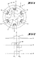
- the reluctance motor 1 shown in FIG. 1 settles essentially a stator 2 and a rotor 3 together, with pronounced stator and rotor poles 4, 5 in an uneven number.
- Fig. 1 is a typical structure a 6/4-pole motor 1 shown.
- the time measurement can be done in the simplest way by a Microcontroller control can be realized. To do this an internal counter when the voltage U is switched on started and when the maximum current is exceeded I Max stopped.
Landscapes
- Engineering & Computer Science (AREA)
- Power Engineering (AREA)
- Control Of Electric Motors In General (AREA)
- Synchronous Machinery (AREA)
Claims (9)
- Procédé de commande d'un moteur à réluctance (1) comprenant un rotor (3) et un stator (2), le stator (2) présentant des bobines de stator (6) individuelles et, respectivement, selon la charge du moteur (1), une intensité (I) prédéfinie passant dans une bobine (6), sachant que, en outre, l'intensité (I) prédéfinie résulte de l'application d'une tension (U) constante, caractérisé en ce que, en cas d'application de la tension (U), le temps (t1, t2), s'écoulant jusqu'à atteindre la valeur d'intensité maximale (I Max), est mesuré, en ce que le temps (t1, t2) mesuré est utilisé comme indication quantitative du degré de charge du moteur, et en ce que l'intensité (I) prédéfinie est conservée par isolement et branchement de la tension constante (U), sachant que la tension (U) étant positive et branchée sur la bobine jusqu'à ce que l'on dépasse la valeur d'intensité maximale (I Max), et l'isolement et le branchement étant ensuite effectués pour maintenir l'intensité de valeur prédéfinie.
- Procédé selon la revendication 1, caractérisé en ce que, lorsque une intensité limite (Ilimite) est atteinte, on effectue une diminution de la vitesse de rotation pour empêcher que le moteur subisse une surcharge.
- Procédé selon l'une des revendications précédentes, caractérisé en ce que la mesure de temps est effectuée par démarrage (Z1) d'un compteur interne, lors du branchement de la tension (U) et arrêt (Z2) du compteur, en cas de dépassement d'une valeur d'intensité maximale (I Max).
- Procédé selon la revendication 3, caractérisé en ce qu'une réduction de la vitesse de rotation est commandée, déclenchée par l'atteinte d'une valeur de compteur minimale.
- Procédé selon l'une des revendications précédentes, caractérisé en ce qu'une commande des intensités de stator est effectuée en fonction du temps (t1, t2) mesuré.
- Procédé selon l'une des revendications précédentes, caractérisé en ce que l'intensité (I) prédéfinie est modifiable.
- Procédé selon la revendication 6, caractérisé en ce que l'intensité (I) prédéfinie est modifiable de façon progressive et continue.
- Procédé selon l'une des revendications précédentes, caractérisé en ce que la commande des courants de stator est effectuée au moyen d'un convertisseur (7).
- Procédé selon la revendication 8, caractérisé en ce que plusieurs moteurs à réluctance (1', 1", 1''') à vitesse de rotation synchrone sont commandés par le convertisseur ou convertisseur (7).
Applications Claiming Priority (5)
| Application Number | Priority Date | Filing Date | Title |
|---|---|---|---|
| DE19725113 | 1997-06-13 | ||
| DE19725113 | 1997-06-13 | ||
| DE19825926A DE19825926A1 (de) | 1997-06-13 | 1998-06-10 | Reluktanzmotor |
| DE19825926 | 1998-06-10 | ||
| PCT/EP1998/003538 WO1998057419A1 (fr) | 1997-06-13 | 1998-06-12 | Moteur a reluctance |
Publications (2)
| Publication Number | Publication Date |
|---|---|
| EP0988689A1 EP0988689A1 (fr) | 2000-03-29 |
| EP0988689B1 true EP0988689B1 (fr) | 2004-05-06 |
Family
ID=26037424
Family Applications (1)
| Application Number | Title | Priority Date | Filing Date |
|---|---|---|---|
| EP98936329A Expired - Lifetime EP0988689B1 (fr) | 1997-06-13 | 1998-06-12 | Moteur a reluctance |
Country Status (8)
| Country | Link |
|---|---|
| EP (1) | EP0988689B1 (fr) |
| AT (1) | ATE266273T1 (fr) |
| AU (1) | AU8537398A (fr) |
| CZ (1) | CZ296265B6 (fr) |
| ES (1) | ES2216300T3 (fr) |
| PL (1) | PL187196B1 (fr) |
| SK (1) | SK285633B6 (fr) |
| WO (1) | WO1998057419A1 (fr) |
Family Cites Families (2)
| Publication number | Priority date | Publication date | Assignee | Title |
|---|---|---|---|---|
| GB9120404D0 (en) * | 1991-09-25 | 1991-11-06 | Switched Reluctance Drives Ltd | Control of switched reluctance machines |
| US5525887A (en) * | 1995-03-14 | 1996-06-11 | A. O. Smith Corporation | Switched reluctance motor providing rotor position detection at low speeds without a separate rotor shaft position sensor |
-
1998
- 1998-06-12 AT AT98936329T patent/ATE266273T1/de not_active IP Right Cessation
- 1998-06-12 PL PL98337238A patent/PL187196B1/pl unknown
- 1998-06-12 EP EP98936329A patent/EP0988689B1/fr not_active Expired - Lifetime
- 1998-06-12 AU AU85373/98A patent/AU8537398A/en not_active Abandoned
- 1998-06-12 WO PCT/EP1998/003538 patent/WO1998057419A1/fr not_active Ceased
- 1998-06-12 CZ CZ0406999A patent/CZ296265B6/cs not_active IP Right Cessation
- 1998-06-12 ES ES98936329T patent/ES2216300T3/es not_active Expired - Lifetime
- 1998-06-12 SK SK1601-99A patent/SK285633B6/sk unknown
Also Published As
| Publication number | Publication date |
|---|---|
| ES2216300T3 (es) | 2004-10-16 |
| WO1998057419A1 (fr) | 1998-12-17 |
| CZ296265B6 (cs) | 2006-02-15 |
| EP0988689A1 (fr) | 2000-03-29 |
| AU8537398A (en) | 1998-12-30 |
| SK285633B6 (sk) | 2007-05-03 |
| PL337238A1 (en) | 2000-08-14 |
| PL187196B1 (pl) | 2004-05-31 |
| SK160199A3 (en) | 2000-08-14 |
| CZ9904069A3 (cs) | 2000-10-11 |
| ATE266273T1 (de) | 2004-05-15 |
Similar Documents
| Publication | Publication Date | Title |
|---|---|---|
| DE4124240C2 (de) | Verfahren zur Regelung des Motorstroms eines bürstenlosen Gleichstommotors | |
| DE69518553T2 (de) | Vorrichtung zur Leistungserzeugung für Fahrzeuge | |
| EP0803465B1 (fr) | Installation pour détecter la charge momentanée et/ou la sollicitation de longue durée de moyens de manipulation, en particulier de dispositifs de levage | |
| DE3779752T2 (de) | Motorerregungsschaltung. | |
| DE19956104A1 (de) | Sensorlose Erfassung eines festgestellten Rotors eines Motors mit geschalteter Reluktanz | |
| DE69830958T2 (de) | System und Verfahren zum Bremsen eines Stellantriebes mit einem bürstenlosen Motor | |
| DE19843924A1 (de) | Berührungslose Steuerung eines Motors mit geschalteter Reluktanz | |
| EP1514342B1 (fr) | Procede et ensemble de circuits pour faire fonctionner des moteurs pas a pas | |
| DE102004055073A1 (de) | Überlastschutz für Gleichstrommotoren | |
| EP0771065B1 (fr) | Procédé pour le démarrage d'un entraínement électrique à vitesse de rotation variable | |
| EP0397818B1 (fr) | Procede et dispositif pour modifier la valeur effective de la vitesse de rotation d'un moteur asynchrone polyphase et systeme de moteurs convenant pour la mise en uvre de ce procede | |
| DE19946050A1 (de) | Verfahren zur Drehzahlregelung für geschaltete Reluktanzmotoren (GRM) | |
| DE3044027C2 (de) | Stromregler für einen Gleichstrommotor | |
| DE4026366C2 (fr) | ||
| DE19825926A1 (de) | Reluktanzmotor | |
| DE2938625A1 (de) | Schaltungsanordnung zum energiesparen | |
| DE2414721C3 (de) | Verfahren zur Steuerung der Drehzahl- bzw. Geschwindigkeit einer frequenzumrichtergespeisten Drehstrom-Asynchronmaschine | |
| EP0993697B1 (fr) | Moteur electrique et mode d'utilisation d'un tel moteur | |
| DE3409299C2 (de) | Ein- oder mehrphasiger Wechselstromsteller mit Impulsbreitensteuerung | |
| EP0988689A1 (fr) | Moteur a reluctance | |
| DE19619190C1 (de) | Bremssteuervorrichtung für den Fahrantrieb eines Flurförderzeugs für höhere Fahrgeschwindigkeiten | |
| DE102020106106A1 (de) | Elektromotor sowie Ansteuerungsverfahren | |
| DE4410959C2 (de) | Verfahren zum Anlassen eines Schleifringläufermotors | |
| DE2829657C2 (de) | Drehzahlbegrenzung für einen Reihenschlußmotor | |
| EP1407536B1 (fr) | Procede de commande d'un moteur a reluctance |
Legal Events
| Date | Code | Title | Description |
|---|---|---|---|
| PUAI | Public reference made under article 153(3) epc to a published international application that has entered the european phase |
Free format text: ORIGINAL CODE: 0009012 |
|
| 17P | Request for examination filed |
Effective date: 19991124 |
|
| AK | Designated contracting states |
Kind code of ref document: A1 Designated state(s): AT BE CH DE DK ES FI FR GB GR IE IT LI NL PT SE |
|
| AX | Request for extension of the european patent |
Free format text: LT PAYMENT 19991124;LV PAYMENT 19991124;SI PAYMENT 19991124 |
|
| 17Q | First examination report despatched |
Effective date: 20001004 |
|
| GRAP | Despatch of communication of intention to grant a patent |
Free format text: ORIGINAL CODE: EPIDOSNIGR1 |
|
| GRAS | Grant fee paid |
Free format text: ORIGINAL CODE: EPIDOSNIGR3 |
|
| GRAA | (expected) grant |
Free format text: ORIGINAL CODE: 0009210 |
|
| AK | Designated contracting states |
Kind code of ref document: B1 Designated state(s): AT BE CH DE DK ES FI FR GB GR IE IT LI NL PT SE |
|
| AX | Request for extension of the european patent |
Extension state: LT LV SI |
|
| PG25 | Lapsed in a contracting state [announced via postgrant information from national office to epo] |
Ref country code: NL Free format text: LAPSE BECAUSE OF FAILURE TO SUBMIT A TRANSLATION OF THE DESCRIPTION OR TO PAY THE FEE WITHIN THE PRESCRIBED TIME-LIMIT Effective date: 20040506 Ref country code: IE Free format text: LAPSE BECAUSE OF FAILURE TO SUBMIT A TRANSLATION OF THE DESCRIPTION OR TO PAY THE FEE WITHIN THE PRESCRIBED TIME-LIMIT Effective date: 20040506 Ref country code: FI Free format text: LAPSE BECAUSE OF FAILURE TO SUBMIT A TRANSLATION OF THE DESCRIPTION OR TO PAY THE FEE WITHIN THE PRESCRIBED TIME-LIMIT Effective date: 20040506 |
|
| REG | Reference to a national code |
Ref country code: GB Ref legal event code: FG4D Free format text: NOT ENGLISH |
|
| REG | Reference to a national code |
Ref country code: CH Ref legal event code: EP |
|
| REF | Corresponds to: |
Ref document number: 59811337 Country of ref document: DE Date of ref document: 20040609 Kind code of ref document: P |
|
| REG | Reference to a national code |
Ref country code: IE Ref legal event code: FG4D Free format text: GERMAN |
|
| PG25 | Lapsed in a contracting state [announced via postgrant information from national office to epo] |
Ref country code: LI Free format text: LAPSE BECAUSE OF NON-PAYMENT OF DUE FEES Effective date: 20040630 Ref country code: CH Free format text: LAPSE BECAUSE OF NON-PAYMENT OF DUE FEES Effective date: 20040630 Ref country code: BE Free format text: LAPSE BECAUSE OF NON-PAYMENT OF DUE FEES Effective date: 20040630 |
|
| REG | Reference to a national code |
Ref country code: CH Ref legal event code: NV Representative=s name: R. A. EGLI & CO. PATENTANWAELTE |
|
| PG25 | Lapsed in a contracting state [announced via postgrant information from national office to epo] |
Ref country code: SE Free format text: LAPSE BECAUSE OF FAILURE TO SUBMIT A TRANSLATION OF THE DESCRIPTION OR TO PAY THE FEE WITHIN THE PRESCRIBED TIME-LIMIT Effective date: 20040806 Ref country code: GR Free format text: LAPSE BECAUSE OF FAILURE TO SUBMIT A TRANSLATION OF THE DESCRIPTION OR TO PAY THE FEE WITHIN THE PRESCRIBED TIME-LIMIT Effective date: 20040806 Ref country code: DK Free format text: LAPSE BECAUSE OF FAILURE TO SUBMIT A TRANSLATION OF THE DESCRIPTION OR TO PAY THE FEE WITHIN THE PRESCRIBED TIME-LIMIT Effective date: 20040806 |
|
| GBT | Gb: translation of ep patent filed (gb section 77(6)(a)/1977) |
Effective date: 20040803 |
|
| REG | Reference to a national code |
Ref country code: ES Ref legal event code: FG2A Ref document number: 2216300 Country of ref document: ES Kind code of ref document: T3 |
|
| LTIE | Lt: invalidation of european patent or patent extension |
Effective date: 20040506 |
|
| NLV1 | Nl: lapsed or annulled due to failure to fulfill the requirements of art. 29p and 29m of the patents act | ||
| ET | Fr: translation filed | ||
| REG | Reference to a national code |
Ref country code: IE Ref legal event code: FD4D |
|
| BERE | Be: lapsed |
Owner name: VORWERK & CO. INTERHOLDING G.M.B.H. Effective date: 20040630 |
|
| REG | Reference to a national code |
Ref country code: CH Ref legal event code: PL |
|
| PLBE | No opposition filed within time limit |
Free format text: ORIGINAL CODE: 0009261 |
|
| STAA | Information on the status of an ep patent application or granted ep patent |
Free format text: STATUS: NO OPPOSITION FILED WITHIN TIME LIMIT |
|
| 26N | No opposition filed |
Effective date: 20050208 |
|
| PGFP | Annual fee paid to national office [announced via postgrant information from national office to epo] |
Ref country code: GB Payment date: 20060605 Year of fee payment: 9 |
|
| REG | Reference to a national code |
Ref country code: HK Ref legal event code: WD Ref document number: 1026984 Country of ref document: HK |
|
| PGFP | Annual fee paid to national office [announced via postgrant information from national office to epo] |
Ref country code: AT Payment date: 20070605 Year of fee payment: 10 |
|
| PG25 | Lapsed in a contracting state [announced via postgrant information from national office to epo] |
Ref country code: PT Free format text: LAPSE BECAUSE OF NON-PAYMENT OF DUE FEES Effective date: 20041006 |
|
| GBPC | Gb: european patent ceased through non-payment of renewal fee |
Effective date: 20070612 |
|
| PG25 | Lapsed in a contracting state [announced via postgrant information from national office to epo] |
Ref country code: GB Free format text: LAPSE BECAUSE OF NON-PAYMENT OF DUE FEES Effective date: 20070612 |
|
| PG25 | Lapsed in a contracting state [announced via postgrant information from national office to epo] |
Ref country code: AT Free format text: LAPSE BECAUSE OF NON-PAYMENT OF DUE FEES Effective date: 20080612 |
|
| PGFP | Annual fee paid to national office [announced via postgrant information from national office to epo] |
Ref country code: IT Payment date: 20120626 Year of fee payment: 15 |
|
| PG25 | Lapsed in a contracting state [announced via postgrant information from national office to epo] |
Ref country code: IT Free format text: LAPSE BECAUSE OF NON-PAYMENT OF DUE FEES Effective date: 20130612 |
|
| REG | Reference to a national code |
Ref country code: FR Ref legal event code: PLFP Year of fee payment: 19 |
|
| REG | Reference to a national code |
Ref country code: FR Ref legal event code: PLFP Year of fee payment: 20 |
|
| PGFP | Annual fee paid to national office [announced via postgrant information from national office to epo] |
Ref country code: FR Payment date: 20170621 Year of fee payment: 20 Ref country code: DE Payment date: 20170621 Year of fee payment: 20 |
|
| PGFP | Annual fee paid to national office [announced via postgrant information from national office to epo] |
Ref country code: ES Payment date: 20170703 Year of fee payment: 20 |
|
| REG | Reference to a national code |
Ref country code: DE Ref legal event code: R071 Ref document number: 59811337 Country of ref document: DE |
|
| REG | Reference to a national code |
Ref country code: ES Ref legal event code: FD2A Effective date: 20200723 |
|
| PG25 | Lapsed in a contracting state [announced via postgrant information from national office to epo] |
Ref country code: ES Free format text: LAPSE BECAUSE OF EXPIRATION OF PROTECTION Effective date: 20180613 |