EP0803610A2 - Machine et méthode pour placer le ballast d'une voie ferrée - Google Patents
Machine et méthode pour placer le ballast d'une voie ferrée Download PDFInfo
- Publication number
- EP0803610A2 EP0803610A2 EP97890049A EP97890049A EP0803610A2 EP 0803610 A2 EP0803610 A2 EP 0803610A2 EP 97890049 A EP97890049 A EP 97890049A EP 97890049 A EP97890049 A EP 97890049A EP 0803610 A2 EP0803610 A2 EP 0803610A2
- Authority
- EP
- European Patent Office
- Prior art keywords
- ballast
- machine
- track
- stripping
- assigned
- Prior art date
- Legal status (The legal status is an assumption and is not a legal conclusion. Google has not performed a legal analysis and makes no representation as to the accuracy of the status listed.)
- Withdrawn
Links
Images
Classifications
-
- E—FIXED CONSTRUCTIONS
- E01—CONSTRUCTION OF ROADS, RAILWAYS, OR BRIDGES
- E01B—PERMANENT WAY; PERMANENT-WAY TOOLS; MACHINES FOR MAKING RAILWAYS OF ALL KINDS
- E01B27/00—Placing, renewing, working, cleaning, or taking-up the ballast, with or without concurrent work on the track; Devices therefor; Packing sleepers
- E01B27/02—Placing the ballast; Making ballastway; Redistributing ballasting material; Machines or devices therefor; Levelling means
-
- E—FIXED CONSTRUCTIONS
- E01—CONSTRUCTION OF ROADS, RAILWAYS, OR BRIDGES
- E01B—PERMANENT WAY; PERMANENT-WAY TOOLS; MACHINES FOR MAKING RAILWAYS OF ALL KINDS
- E01B2203/00—Devices for working the railway-superstructure
- E01B2203/01—Devices for working the railway-superstructure with track
- E01B2203/012—Devices for working the railway-superstructure with track present, i.e. in its normal position
-
- E—FIXED CONSTRUCTIONS
- E01—CONSTRUCTION OF ROADS, RAILWAYS, OR BRIDGES
- E01B—PERMANENT WAY; PERMANENT-WAY TOOLS; MACHINES FOR MAKING RAILWAYS OF ALL KINDS
- E01B2203/00—Devices for working the railway-superstructure
- E01B2203/06—Placing ballast
-
- E—FIXED CONSTRUCTIONS
- E01—CONSTRUCTION OF ROADS, RAILWAYS, OR BRIDGES
- E01B—PERMANENT WAY; PERMANENT-WAY TOOLS; MACHINES FOR MAKING RAILWAYS OF ALL KINDS
- E01B2203/00—Devices for working the railway-superstructure
- E01B2203/08—Levelling ballast or ground beneath
- E01B2203/083—Ploughs
Definitions
- the invention relates to a machine and a method for ballasting a track.
- a machine for distributing and leveling ballast ballast is known from US Pat. No. 5,052,132.
- This machine which is supported on rail bogies and can be moved on a track, is equipped with a ballast plow and a rotating sweeping brush.
- the sweeping brush is connected via a conveyor belt running in the longitudinal direction of the machine to a ballast store having a floor conveyor belt.
- a ballast discharge device In the discharge area of the floor conveyor belt, this is assigned a ballast discharge device, which essentially consists of four chutes spaced apart from one another in the cross-machine direction and drop conveyor belts attached to the lower end thereof.
- Each discharge conveyor belt which can be set in rotation by a drive, can be pivoted about a vertical axis, so that the thrown-up ballast can, if desired, be fed to different track sections.
- the rotational speed of the discharge conveyor belt By changing the rotational speed of the discharge conveyor belt, the amount of ballast thrown can be changed if necessary.
- a scraper unit that is height-adjustable by a drive is provided, which is composed of a large number of rubber parts running in the vertical direction and thus forms a kind of curtain in order to scrape the ballast falling onto the track from the sleepers into the intermediate compartments. This leads to a relief of the sweeping brush which follows in the working direction and concludes the ballasting process.
- ballast grading machine is described by GB-B-2 036 142, to which a ballast store with chutes for ballast discharge and a rotating sweeping brush is assigned.
- the object of the present invention is to create a machine of the type mentioned at the outset, with which a uniform track ballast is ensured, regardless of a different state of ballast in the track.
- each chute is designed to be extendable downward in the direction of the track by means of a scraper unit which can be adjusted relative to the shedding end by means of a drive, the scraper unit having an insertion opening assigned to the shedding end and an outlet opening forming a scraper edge and the scraper edge is arranged parallel to a reference plane formed by wheel contact points of the rail bogies.
- Such a scraper unit makes it possible to ensure a uniform ballast of the track with optional, constant distancing of the scraper edge from the threshold. This is possible in that a ballast accumulation is always kept in stock in the stripping unit, so that even if there is a fluctuating ballast requirement resulting from a different ballast situation of the track, the amount of ballast required for a uniform ballast flow automatically.
- the scraper edge can be used to produce a uniformly high ballast belt with which, on the one hand, an effective, uniform ballast is ensured for a permanent track position and, on the other hand, the supply of excess ballast is reliably excluded in a particularly economical manner.
- the particularly simple construction is also particularly advantageous.
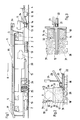
- the machine 1 shown in FIG. 1 has a machine frame 4 which can be moved on rail carriages 2 and 10 by means of a travel drive 3 and which is formed from two frame parts which are connected to one another in an articulated manner.
- Driving cabs 5 with a control device 6 and a motor 7 are assigned to the machine frame 4.
- Each chute 13 is designed to be extendable in the direction of a track 15 by means of an annular stripping unit 14.
- the stripping unit 14 shown in the lowered working position - in contrast to FIG. 1 - has one end of the stripping 12 of the chute 13 assigned insertion opening 16 and an outlet opening 17 located in the lower end region. This forms an endless scraper edge 18 which, in the working position, runs parallel with respect to a reference plane 20 formed by wheel contact points 19 of the rail carriages 2 and 10.
- the stripping unit 14 is equipped with a flange roller 21 for support on a rail 22 of the track 15 and is articulated to the machine frame 4 via a link rod 23 running in the machine longitudinal direction. With the aid of a drive 24, the stripping unit 14 can be adjusted from a transfer position shown in FIG. 1 into the working position shown in FIG. 2. As can be seen in particular in FIG. 3, each rail 22 of the track 15 is assigned a pair of stripping units 14 which are structurally connected to form a unit. In order to optionally produce a different height of the ballast belt 31, the stripping unit 14 could alternatively be designed to be adjustable relative to the flanged roller 21 with the aid of a drive.
- ballast 27 is thrown onto sleepers 28 of the track 15 as part of a track tamping carried out by tamping and lifting straightening units 25, 26 using the ballast store 11.
- a stripping unit 14 which extends the chutes 13 and is formed in a ring in a horizontal cross section, is lowered onto the track 15 by acting on the drive 24. Consequently, the wiping edge 18 is positioned at a constant distance of a few centimeters from the upper edge of the sleepers 28.
- By opening the control flaps 9 of the chute 13 so much ballast is thrown away that there is a permanent accumulation of ballast 29 within the stripping unit 14.
- ballast accumulation 29 is scanned by an echo sounder 32. This is about a control circuit 33 is connected to a drive 34 of the control flap 9 which changes the cross section of the chute 13. The different ballast outflow is thus automatically compensated for by appropriate adjustment of the control flaps 9.
- the ballast store 11 can be filled with the aid of a conveyor belt 35 running in the longitudinal direction of the machine and attached to the upper end of the machine 1. While its discharge end 36 is located above the ballast store 11, a receiving end 37 is provided at the rear end of the machine 1. With the aid of the conveyor belt 35, the ballast storage 11 can be continuously supplied with ballast from storage wagons, not shown, which are coupled to the machine 1 at the rear end.
- the specially designed tamping machine 1 shown in FIGS. 1 to 3 is particularly suitable, for example, for a track correction following a ballast bed cleaning, in which only a reduced amount of cleaned ballast can be thrown back into the track by removing larger amounts of overburden.
- a uniform ballast is ensured by applying ballast strips 31 both in the sleeper head area and between the rails 22, with the targeted supply of ballast with the help of the stripping units 14 underneath Achieving a saving in ballast, only the amount of ballast required is delivered.
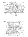
- the ballast store 11 is located approximately in the middle between the two rail carriages 2.
- the loading takes place by means of a first conveyor belt 38 running in the machine longitudinal direction, while with the help of a second conveyor belt 39, which is partially arranged below an outlet opening of the ballast store 11, ballast is fed from the ballast store to a cleaning machine (not shown in detail).
- the ballast store 11 also has four in the cross-machine direction Chutes 13 spaced apart from one another with scraper units 14, the two central chutes 13 positioned between the rails 22 being assigned a common scraper unit 14 which can be supported on the rails 22 via the flange rollers 21.
- the flange wheels 21 can be adjusted in height with the aid of a drive 40 relative to the stripping unit 14, as a result of which the stripping edge 18 can be removed from the upper edge of the threshold by an operator located in a work cabin 48, depending on the need for ballast.
- the stripping unit 14 of the two outer chutes 13 each has a tunnel 41 running in the machine longitudinal direction in order to prevent the ballast of a busbar 42.
- the stripping unit 14 is supported by the drive 24 so as to be displaceable in the longitudinal direction of the chute 13.
- a distance measuring device 43 is provided to measure the distance between the scraper edge 18 and the chute 13. This enables the production of gravel strips at a desired height.
- the chute 13 together with the stripping unit 14 is designed to be adjustable transversely to the machine longitudinal direction by a drive 44. Control flaps 9 located in the chute 13 are opened to a maximum during the entire ballast, so that the ballast accumulation 29 in the form of a ballast column extends into the ballast storage stored in the ballast store 11 (in FIG. 5, because of the ballast, the better overview is only in the left half of the picture indicated).
- An echo sounder 45 arranged in the ballast accumulator 11 is connected via the control circuit 33 to a drive 46 of the first conveyor belt 38 and acts on it in such a way that a ballast accumulation 47 in the ballast accumulator 11 remains constant regardless of the ballast outflow via the second conveyor belt 39 or the chutes 13.
Landscapes
- Engineering & Computer Science (AREA)
- Architecture (AREA)
- Civil Engineering (AREA)
- Structural Engineering (AREA)
- Machines For Laying And Maintaining Railways (AREA)
Applications Claiming Priority (2)
| Application Number | Priority Date | Filing Date | Title |
|---|---|---|---|
| AT73596 | 1996-04-23 | ||
| AT735/96 | 1996-04-23 |
Publications (2)
| Publication Number | Publication Date |
|---|---|
| EP0803610A2 true EP0803610A2 (fr) | 1997-10-29 |
| EP0803610A3 EP0803610A3 (fr) | 1998-11-11 |
Family
ID=3498424
Family Applications (1)
| Application Number | Title | Priority Date | Filing Date |
|---|---|---|---|
| EP97890049A Withdrawn EP0803610A3 (fr) | 1996-04-23 | 1997-03-18 | Machine et méthode pour placer le ballast d'une voie ferrée |
Country Status (6)
| Country | Link |
|---|---|
| US (1) | US5937763A (fr) |
| EP (1) | EP0803610A3 (fr) |
| JP (1) | JPH1037104A (fr) |
| CN (1) | CN1165890A (fr) |
| AU (1) | AU713189B2 (fr) |
| CA (1) | CA2203337A1 (fr) |
Cited By (1)
| Publication number | Priority date | Publication date | Assignee | Title |
|---|---|---|---|---|
| DE19821825B4 (de) * | 1997-05-28 | 2008-10-30 | Franz Plasser Bahnbaumaschinen-Industriegesellschaft M.B.H. | Schüttgutverladewagen |
Families Citing this family (8)
| Publication number | Priority date | Publication date | Assignee | Title |
|---|---|---|---|---|
| AT3379U3 (de) * | 1999-12-07 | 2000-11-27 | Plasser Bahnbaumasch Franz | Verfahren zur verlegung eines gleises und maschine zur ablage eines gleises |
| EP1191145B1 (fr) * | 2000-09-22 | 2003-02-26 | Rhomberg Bau GmbH | Procédé et dispositif pour relier une voie ferrée comprenant des rails et des plots d'appui unitaires à une structure fixe de soubassement de voie |
| AT500949B8 (de) * | 2004-10-01 | 2007-02-15 | Plasser Bahnbaumasch Franz | Maschine zur durchführung einer gleislagekorrektur |
| CN103088731B (zh) * | 2011-11-03 | 2016-10-05 | 科思创聚合物(中国)有限公司 | 浇注发泡车 |
| JP5907798B2 (ja) * | 2012-05-08 | 2016-04-26 | 保線機器整備株式会社 | 砕石散布装置 |
| CN103835194A (zh) * | 2012-11-27 | 2014-06-04 | 拜耳材料科技(中国)有限公司 | 压力分配装置及使用其对铁轨施压以保持轨面标高的方法 |
| CN110230237A (zh) * | 2019-05-31 | 2019-09-13 | 中铁五局集团有限公司 | 一种道碴铺设装置 |
| CN116411492B (zh) * | 2023-04-03 | 2025-12-19 | 昌九城际铁路股份有限公司 | 一种铁路路基施工用道碴铺设装置 |
Family Cites Families (12)
| Publication number | Priority date | Publication date | Assignee | Title |
|---|---|---|---|---|
| US1743579A (en) * | 1927-08-06 | 1930-01-14 | Automatic Ballast Spreader Cor | Means for discharging ballast |
| CH408085A (de) * | 1962-02-12 | 1966-02-28 | Reichsbahn Der Generaldirektor | Vorrichtung zum Verteilen von Gleisschotter |
| AT363115B (de) * | 1978-05-09 | 1981-07-10 | Plasser Bahnbaumasch Franz | Selbstfahrbare gleisbett-reinigungsmaschine mit speichervorrichtung |
| AT364912B (de) * | 1978-11-27 | 1981-11-25 | Plasser Bahnbaumasch Franz | Gleis-schotterplaniermaschine mit raeumwalzen-anordnung |
| FR2498220A1 (fr) * | 1981-01-22 | 1982-07-23 | Sotramef | Machine a substituer les traverses de voies ferrees et procede d'utilisation |
| IT1187615B (it) * | 1985-12-17 | 1987-12-23 | Danieli Off Mecc | Gruppo distributore del pietrisco per risanatrice per massicciata e risanatrice adottante detto gruppo distributore |
| AT386432B (de) * | 1986-02-12 | 1988-08-25 | Plasser Bahnbaumasch Franz | Fahrbare anlage zum reinigen und anschliessenden verdichten der schotterbettung von gleisen |
| AT389336B (de) * | 1986-02-12 | 1989-11-27 | Plasser Bahnbaumasch Franz | Gleisstopfmaschine mit hebe-, stopf- und gegebenenfalls richtaggregat |
| AT389333B (de) * | 1986-09-08 | 1989-11-27 | Plasser Bahnbaumasch Franz | Gleisverfahrbare schuettgutverladewagen-anordnung mit regelbaren entladeschurren |
| DE59000696D1 (de) * | 1990-01-10 | 1993-02-11 | Plasser Bahnbaumasch Franz | Gleisstopfmaschine. |
| AT404039B (de) * | 1990-03-21 | 1998-07-27 | Plasser Bahnbaumasch Franz | Maschine zum verteilen und planieren des bettungsschotters |
| US5201127A (en) * | 1992-02-19 | 1993-04-13 | Keshaw Manufacturing Company, Inc. | Self metering ballast system |
-
1997
- 1997-03-17 US US08/819,389 patent/US5937763A/en not_active Expired - Fee Related
- 1997-03-18 EP EP97890049A patent/EP0803610A3/fr not_active Withdrawn
- 1997-04-21 CN CN97110587.1A patent/CN1165890A/zh active Pending
- 1997-04-22 AU AU19015/97A patent/AU713189B2/en not_active Ceased
- 1997-04-22 CA CA002203337A patent/CA2203337A1/fr not_active Abandoned
- 1997-04-22 JP JP9104338A patent/JPH1037104A/ja not_active Withdrawn
Cited By (1)
| Publication number | Priority date | Publication date | Assignee | Title |
|---|---|---|---|---|
| DE19821825B4 (de) * | 1997-05-28 | 2008-10-30 | Franz Plasser Bahnbaumaschinen-Industriegesellschaft M.B.H. | Schüttgutverladewagen |
Also Published As
| Publication number | Publication date |
|---|---|
| US5937763A (en) | 1999-08-17 |
| AU713189B2 (en) | 1999-11-25 |
| JPH1037104A (ja) | 1998-02-10 |
| AU1901597A (en) | 1997-10-30 |
| CN1165890A (zh) | 1997-11-26 |
| EP0803610A3 (fr) | 1998-11-11 |
| CA2203337A1 (fr) | 1997-10-23 |
Similar Documents
| Publication | Publication Date | Title |
|---|---|---|
| EP0255564B1 (fr) | Machine pour remplacer ou rénover respectivement les rails et les traverses d'une voie existante | |
| DE2057182C3 (de) | Verfahren und Maschine zur Behandlung des Bettungsschotters von Eisenbahngleisen | |
| DE3634397C2 (de) | Fahrbare Anlage zum Reinigen und anschließenden Verdichten der Schotterbettung von Gleisen | |
| EP0681062A2 (fr) | Installation pour l'assainissement de l'infrastructure du ballast d'une voie ferrée | |
| EP0633355B1 (fr) | Machine de balayage d'une voie ferrée | |
| EP1172481B1 (fr) | Machine de renouvellement d'une voie ferrée | |
| AT402952B (de) | Gleisbaumaschine zum kontrollierten absenken einesgleises | |
| DE3430291A1 (de) | Verfahren und maschine zum reinigen einer gleis-schotterbettung | |
| EP0771909B1 (fr) | Machine pour le démontage d'une ancienne voie ferrée et l'installation d'une nouvelle voie | |
| DE2853099C2 (de) | Selbstfahrbare Gleisbett-Reinigungsmaschine mit Speichervorrichtung | |
| EP0408839A1 (fr) | Ensemble de machines déplaçable sur voie pour enlever, nettoyer et remettre en place le ballast d'une voie ferrée | |
| AT404039B (de) | Maschine zum verteilen und planieren des bettungsschotters | |
| DE9215207U1 (de) | Anlage zur Herstellung einer Planumschutzschichte | |
| EP0609647B1 (fr) | Machine pour le renouvellement ou nettoyage d'un lit de ballast | |
| EP0499016A2 (fr) | Machine de nettoyage | |
| EP0416135B1 (fr) | Machine mobile sur rails pour distribuer et profiler le lit de ballast d'une voie ferrée | |
| DE3819717A1 (de) | Kontinuierlich (non-stop) verfahrbare gleisbaumaschine | |
| EP0803610A2 (fr) | Machine et méthode pour placer le ballast d'une voie ferrée | |
| EP1179634B1 (fr) | Machine de renouvellement d'une voie ferrée | |
| EP1195468B1 (fr) | Machine de renouvellement d'une voie ferrée | |
| CH683273A5 (de) | Gleisverfahrbare Maschine zum Verteilen und Profilieren des Bettungsschotters. | |
| EP0428781B1 (fr) | Machine de construction pour voies ferrées pour répartir et mettre en forme le ballast d'une voie | |
| AT398593B (de) | Anlage zum einschottern und unterstopfen eines gleises | |
| DE3151030A1 (de) | Fahrbare anlage zur herstellung einer zwischen planum und schotterbett eines gleises verlaufenden schutzschichte | |
| EP2182115A1 (fr) | Dispositif de nivellement de ballast |
Legal Events
| Date | Code | Title | Description |
|---|---|---|---|
| PUAI | Public reference made under article 153(3) epc to a published international application that has entered the european phase |
Free format text: ORIGINAL CODE: 0009012 |
|
| 17P | Request for examination filed |
Effective date: 19970401 |
|
| AK | Designated contracting states |
Kind code of ref document: A2 Designated state(s): AT CH DE FI FR GB IT LI SE |
|
| PUAL | Search report despatched |
Free format text: ORIGINAL CODE: 0009013 |
|
| AK | Designated contracting states |
Kind code of ref document: A3 Designated state(s): AT CH DE FI FR GB IT LI SE |
|
| 17Q | First examination report despatched |
Effective date: 20011022 |
|
| STAA | Information on the status of an ep patent application or granted ep patent |
Free format text: STATUS: THE APPLICATION IS DEEMED TO BE WITHDRAWN |
|
| 18D | Application deemed to be withdrawn |
Effective date: 20020304 |