EP0803647A1 - Montage d'un système de prélèvement de combustible-comburant intégré - Google Patents
Montage d'un système de prélèvement de combustible-comburant intégré Download PDFInfo
- Publication number
- EP0803647A1 EP0803647A1 EP97106586A EP97106586A EP0803647A1 EP 0803647 A1 EP0803647 A1 EP 0803647A1 EP 97106586 A EP97106586 A EP 97106586A EP 97106586 A EP97106586 A EP 97106586A EP 0803647 A1 EP0803647 A1 EP 0803647A1
- Authority
- EP
- European Patent Office
- Prior art keywords
- container
- comburent
- assembly according
- fuel
- engine
- Prior art date
- Legal status (The legal status is an assumption and is not a legal conclusion. Google has not performed a legal analysis and makes no representation as to the accuracy of the status listed.)
- Granted
Links
- 239000000446 fuel Substances 0.000 title claims abstract description 28
- 238000001914 filtration Methods 0.000 claims abstract description 13
- 238000002485 combustion reaction Methods 0.000 claims abstract description 6
- 230000008878 coupling Effects 0.000 claims description 2
- 238000010168 coupling process Methods 0.000 claims description 2
- 238000005859 coupling reaction Methods 0.000 claims description 2
- 238000002347 injection Methods 0.000 abstract description 7
- 239000007924 injection Substances 0.000 abstract description 7
- 230000000712 assembly Effects 0.000 description 5
- 238000000429 assembly Methods 0.000 description 5
- 230000001105 regulatory effect Effects 0.000 description 2
- 238000011144 upstream manufacturing Methods 0.000 description 2
- 230000000295 complement effect Effects 0.000 description 1
- 230000001276 controlling effect Effects 0.000 description 1
- 238000007599 discharging Methods 0.000 description 1
- 230000010354 integration Effects 0.000 description 1
- 230000007257 malfunction Effects 0.000 description 1
- 238000012986 modification Methods 0.000 description 1
- 230000004048 modification Effects 0.000 description 1
- 230000001681 protective effect Effects 0.000 description 1
Images

Classifications
-
- F—MECHANICAL ENGINEERING; LIGHTING; HEATING; WEAPONS; BLASTING
- F02—COMBUSTION ENGINES; HOT-GAS OR COMBUSTION-PRODUCT ENGINE PLANTS
- F02M—SUPPLYING COMBUSTION ENGINES IN GENERAL WITH COMBUSTIBLE MIXTURES OR CONSTITUENTS THEREOF
- F02M35/00—Combustion-air cleaners, air intakes, intake silencers, or induction systems specially adapted for, or arranged on, internal-combustion engines
- F02M35/10—Air intakes; Induction systems
- F02M35/104—Intake manifolds
- F02M35/112—Intake manifolds for engines with cylinders all in one line
-
- F—MECHANICAL ENGINEERING; LIGHTING; HEATING; WEAPONS; BLASTING
- F02—COMBUSTION ENGINES; HOT-GAS OR COMBUSTION-PRODUCT ENGINE PLANTS
- F02M—SUPPLYING COMBUSTION ENGINES IN GENERAL WITH COMBUSTIBLE MIXTURES OR CONSTITUENTS THEREOF
- F02M35/00—Combustion-air cleaners, air intakes, intake silencers, or induction systems specially adapted for, or arranged on, internal-combustion engines
- F02M35/10—Air intakes; Induction systems
- F02M35/10006—Air intakes; Induction systems characterised by the position of elements of the air intake system in direction of the air intake flow, i.e. between ambient air inlet and supply to the combustion chamber
- F02M35/10026—Plenum chambers
- F02M35/10052—Plenum chambers special shapes or arrangements of plenum chambers; Constructional details
-
- F—MECHANICAL ENGINEERING; LIGHTING; HEATING; WEAPONS; BLASTING
- F02—COMBUSTION ENGINES; HOT-GAS OR COMBUSTION-PRODUCT ENGINE PLANTS
- F02M—SUPPLYING COMBUSTION ENGINES IN GENERAL WITH COMBUSTIBLE MIXTURES OR CONSTITUENTS THEREOF
- F02M35/00—Combustion-air cleaners, air intakes, intake silencers, or induction systems specially adapted for, or arranged on, internal-combustion engines
- F02M35/10—Air intakes; Induction systems
- F02M35/10209—Fluid connections to the air intake system; their arrangement of pipes, valves or the like
- F02M35/10216—Fuel injectors; Fuel pipes or rails; Fuel pumps or pressure regulators
-
- F—MECHANICAL ENGINEERING; LIGHTING; HEATING; WEAPONS; BLASTING
- F02—COMBUSTION ENGINES; HOT-GAS OR COMBUSTION-PRODUCT ENGINE PLANTS
- F02M—SUPPLYING COMBUSTION ENGINES IN GENERAL WITH COMBUSTIBLE MIXTURES OR CONSTITUENTS THEREOF
- F02M35/00—Combustion-air cleaners, air intakes, intake silencers, or induction systems specially adapted for, or arranged on, internal-combustion engines
- F02M35/10—Air intakes; Induction systems
- F02M35/10373—Sensors for intake systems
- F02M35/1038—Sensors for intake systems for temperature or pressure
-
- F—MECHANICAL ENGINEERING; LIGHTING; HEATING; WEAPONS; BLASTING
- F02—COMBUSTION ENGINES; HOT-GAS OR COMBUSTION-PRODUCT ENGINE PLANTS
- F02M—SUPPLYING COMBUSTION ENGINES IN GENERAL WITH COMBUSTIBLE MIXTURES OR CONSTITUENTS THEREOF
- F02M35/00—Combustion-air cleaners, air intakes, intake silencers, or induction systems specially adapted for, or arranged on, internal-combustion engines
- F02M35/02—Air cleaners
Definitions
- the present invention relates to an integrated fuel and comburent feed assembly.
- combustion engines for motor vehicles are currently provided with fuel and comburent feed assemblies that are substantially independent of one another.
- the comburent feed assembly comprises a comburent intake manifold, directly connected to a multiplicity of intake pipes produced inside a cylinder head of the engine, and a filtration unit for the comburent itself, communicating with the intake manifold by means of a connecting pipe.
- the intake manifold comprises a main pipe, communicating with the filtration unit by means of the connecting pipe, and a multiplicity of secondary pipes extending from the main pipe and each connecting the main pipe itself to a respective intake pipe in the engine's cylinder head.
- the comburent feed assembly further comprises at least one throttled body, arranged inside the main pipe of the intake manifold upstream of the secondary pipes, which is suitable for regulating the amount of comburent which flows inside the intake pipes.
- the fuel feed assembly comprises a multiplicity of injectors, each of which is suitable for introducing inside the respective intake pipe a specific amount of fuel per engine cycle, and a supply pipe, also known as a "flute" ["flauto” in Italian], suitable for supplying pressurized fuel to each injector.
- the fuel feed assembly also comprises a multiplicity of sensors for gathering data essential to the operation of the engine, such as the quantity and temperature of the comburent which flows inside the intake pipes, and an electronic unit which controls each injector and determines, on the basis of the data recorded by the sensors, the amount of fuel and the moment at which that amount should be introduced into each intake pipe.
- the need to arrange an ever-increasing number of devices inside an engine compartment of the motor vehicle has actually imposed the need to position some components of the feed assemblies inside protection containers which are frequently arranged in positions which are particularly narrow and relatively distant from the engine, complicating the architecture of the said feed assemblies.
- the electronic unit for example, is generally arranged in a protected position relatively far away from the engine and is connected to the injectors and to the sensors by means of cables of considerable length, which is often the cause of malfunctions.
- the object of the invention is therefore to produce fuel and comburent feed assemblies which can eliminate the above-mentioned disadvantages.
- an integrated fuel and comburent feed assembly is produced which is suitable for supplying fuel and comburent to at least one intake pipe of a combustion engine, comprising means for feeding the comburent to the said intake pipe, means for filtering the said comburent, and means for supplying the fuel to the said intake pipe; and being characterized in that it comprises a container housing at least the said feed means, the said filtration means, the said supply means, and sensors for recording quantities essential to the operation of the engine.
- the integrated assembly described above is characterized in that the said container houses an electronic control unit.
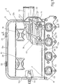
- a combustion engine preferably but not necessarily for motor vehicles, which is provided with a fuel and comburent feed unit 2 which comprises a comburent feed assembly 3, a fuel feed assembly 4 and finally a filtration assembly 5 for the said comburent.
- the unit 2 also comprises a container 6, housing the assemblies 3, 4 and 5, which is suitable for being mounted integral with a wall 7 of the engine 1 having a multiplicity of apertures, each of which defines an inlet 8 of a respective intake pipe 9 of the engine 1 itself.
- the container 6 has a substantially parallelepipedal shape and has a front wall 10 arranged in contact with the wall 7 of the engine 1, a rear wall 11 parallel to and facing the wall 10 and finally four lateral walls, denoted by 12a, 12b, 12c and 12d, which are perpendicular to the walls 10 and 11 and are in parallel pairs perpendicular to each other.
- the container 6 is suitable for being mounted on the engine 1 by means of support brackets 13 which extend from the wall 10 to the outside of the container 6 perpendicular to the said wall 10.
- the container 6 has an internal chamber 14 and is defined by two mutually complementary shell portions 15 and 16 which have respective perimeter end edges 17 and 18 suitable for being coupled together in a fluid-tight manner and in an easily uncouplable way; the wall 10 of the container 6 belongs to the portion 15 whilst the wall 11 belongs to the portion 16.
- the portions 15 and 16 of the container 6 are connected together by means of a hinge 19 and the portion 16 of the container 6 is movable between a closed configuration and an open configuration which permits access to the inside of the said container 6.
- the portions 15 and 16 have respective connection flanges 20 between which a gasket 21 is interposed, and furthermore the portion 16 is provided externally with a multiplicity of coupling devices 22, suitable for mechanically connecting the portions 15 and 16 to each other, and for keeping the flanges 20 clasped on the gasket 21.
- the container 6 is mounted on the engine 1 in such a way that the wall 10, having a multiplicity of apertures 23 (see Fig. 1) is arranged with each aperture 23 aligned to a respective inlet 8 of an intake pipe 9.
- the assembly 3 comprises a main, substantially cylindrical pipe 24 which extends inside the container 6 parallel to a corner 25 of the said container 6 defined by the walls 11 and 12c.
- the pipe 24 is sealed at both ends and is arranged inside the portion 16 of the container 6 with its own lateral wall 26 integral with the walls 11 and 12c of the said container 6.
- the assembly 3 further comprises a tubular body 27 which extends from the wall 26 of the pipe 24 towards the centre of the chamber 14 and has an internal cavity 28 which connects the pipe 24 to the chamber 14, and a multiplicity of secondary pipes 29, each of which connects a respective aperture 23 to the main pipe 24.
- each secondary pipe 29 is sub-divided into two portions 30 and 31, coupled together in a fluid-tight manner, each of which is integral with a respective shell portion 15, 16 of the container 6.
- the portion 30 of the pipe 29 is integral with the wall 11 whilst the portion 31 of the pipe 29 is integral with the walls 10 and 12a of the container 6.
- the tubular body 27 and the secondary pipes 29 define an intake manifold 32 of the assembly 3 suitable for supplying comburent to the intake pipes 9 of the engine 1.
- the comburent supply assembly 3 also has a throttled body 40 which is housed inside the cavity 28 of the tubular body 27 and is suitable for regulating the inflow of comburent inside the main pipe 24.
- the throttled body 40 is controlled in known manner by means of a cable 41 which arrives inside the container 6 through a slit 42 present in the wall 12c.
- the filtration assembly 5 comprises a filtration element 33, arranged perpendicular to the walls 12b and 12d, which sub-divides the chamber 14 into two half-chambers each of which is limited by a respective shell portion 15, 16 of the container 6 itself.
- the half-chamber relative to the portion 15 of the container 6 communicates with the outside through a pipe 34 extending from the wall 12b of the said container 6.
- each secondary pipe 29 has a respective through seat 36, and the fuel feed assembly 4 has an injection device 37, of known type, housed inside each seat 36.
- the injection devices 37 are arranged inside the chamber 14 and are suitable for introducing the fuel into the pipes 29.
- the assembly 4 further has a fuel supply pipe 38 which is connected to each injection device 37 and is suitable for receiving the pressurized fuel from outside the container 6 to supply it to each device 37, and optionally also a drain pipe (not shown) for discharging surplus fuel.
- the supply pipe 38 extends perpendicular to the walls 12b and 12d inside the half-chamber relative to the portion 15 of the container 6 and is connected to the outside of the container 6 via a sleeve 39 projecting from the rear wall 12d.
- the container 6 is provided internally with a multiplicity of sensors 43 for gathering data essential to the operation of the engine 1, such as the amount and temperature of the comburent which flows inside the intake pipes 9, and with an electronic unit 44, housed in the chamber 14, which is connected by means of cables (not shown) to the sensors 43 and to the injection devices 37 and controls each device 37 to determine, on the basis of the data recorded by the sensors 43, the amount of fuel and the moment at which that amount should be introduced into each intake pipe 9.
- the cables reach the injection devices 37 inside a protective sheath 45 which extends inside the chamber 14 parallel to the fuel supply pipe 38 above the said devices 37.
- the container 6 is preferably but not necessarily provided with resonator devices 46 which are arranged upstream and downstream of the filtration element 33 in communication with the chamber 14 and are suitable for reducing the noise produced during the intake of the comburent.
- the comburent feed assembly 3 has a multiplicity of throttled bodies 40 each housed inside a respective secondary pipe 29 of the intake manifold 32.
- the throttled body 40 is controlled by means of an electronic control device (not shown) which is controlled by the electronic unit 44 of the engine 1 which directly controls the inflow of comburent into the intake pipes 9 of the engine 1.
- the container 6 does not have the electronic unit 44 of the engine 1, which is arranged externally to the said container 6, and has an electronic unit (not shown) for controlling the sensors 43 which is arranged inside the chamber 14 and is connected to the electronic unit 44.
- the advantages deriving from the unit 2 described above are essentially a high degree of integration of the components, a reduction of the dimensions inside the engine compartment of the motor vehicle and a reduction of the operations required for mounting the said unit 2 onto the remaining part of the engine 1.
Landscapes
- Engineering & Computer Science (AREA)
- Chemical & Material Sciences (AREA)
- Combustion & Propulsion (AREA)
- Mechanical Engineering (AREA)
- General Engineering & Computer Science (AREA)
- Analytical Chemistry (AREA)
- Physics & Mathematics (AREA)
- Geometry (AREA)
- Fuel-Injection Apparatus (AREA)
- Organic Low-Molecular-Weight Compounds And Preparation Thereof (AREA)
- Solid Fuels And Fuel-Associated Substances (AREA)
Applications Claiming Priority (2)
| Application Number | Priority Date | Filing Date | Title |
|---|---|---|---|
| ITBO960214 | 1996-04-22 | ||
| IT96BO000214A IT1285682B1 (it) | 1996-04-22 | 1996-04-22 | Gruppo integrato di adduzione di carburante e comburente |
Publications (2)
| Publication Number | Publication Date |
|---|---|
| EP0803647A1 true EP0803647A1 (fr) | 1997-10-29 |
| EP0803647B1 EP0803647B1 (fr) | 2002-06-19 |
Family
ID=11341350
Family Applications (1)
| Application Number | Title | Priority Date | Filing Date |
|---|---|---|---|
| EP97106586A Expired - Lifetime EP0803647B1 (fr) | 1996-04-22 | 1997-04-21 | Montage d'un système de prélèvement de combustible-comburant intégré |
Country Status (6)
| Country | Link |
|---|---|
| US (1) | US5816213A (fr) |
| EP (1) | EP0803647B1 (fr) |
| BR (1) | BR9700583A (fr) |
| DE (1) | DE69713448T2 (fr) |
| ES (1) | ES2177857T3 (fr) |
| IT (1) | IT1285682B1 (fr) |
Cited By (2)
| Publication number | Priority date | Publication date | Assignee | Title |
|---|---|---|---|---|
| GB2352774A (en) * | 1999-08-03 | 2001-02-07 | Ford Motor Co | Integrated air induction module for gasoline engines |
| ES2263313A1 (es) * | 2002-11-25 | 2006-12-01 | Honda Motor Co., Ltd | Sistema de admision para motor. |
Families Citing this family (10)
| Publication number | Priority date | Publication date | Assignee | Title |
|---|---|---|---|---|
| DE19521025A1 (de) * | 1995-06-13 | 1996-12-19 | Mann & Hummel Filter | Rohrmodul |
| JPH10274111A (ja) * | 1997-03-28 | 1998-10-13 | Denso Corp | 吸気装置およびその組付け方法 |
| JP3589840B2 (ja) * | 1997-10-30 | 2004-11-17 | 株式会社デンソー | 内燃機関の吸気装置 |
| KR100331454B1 (ko) * | 1998-09-01 | 2002-04-09 | 신구 이이치 | 다기통 내연기관에 있어서의 관성과급식 흡기매니폴드의 구조및 이 흡기매니폴드에 있어서의 브랜치파이프의 접합방법 |
| JP3875417B2 (ja) * | 1998-11-25 | 2007-01-31 | 本田技研工業株式会社 | 車両用エンジンにおける燃料噴射装置 |
| US6308686B1 (en) * | 1999-11-18 | 2001-10-30 | Siemens Canada Limited | Intake manifold with internal fuel rail and injectors |
| JP2003065187A (ja) | 2001-08-22 | 2003-03-05 | Sanshin Ind Co Ltd | 船外機における燃料供給装置 |
| JP2003065183A (ja) * | 2001-08-22 | 2003-03-05 | Sanshin Ind Co Ltd | 船外機における燃料供給装置 |
| US6732717B2 (en) * | 2002-04-17 | 2004-05-11 | Delphi Technologies, Inc. | Fuel rail permeant collection system |
| EP1375895A2 (fr) * | 2002-06-26 | 2004-01-02 | Robert Bosch Gmbh | Dispositif pour former un mélange dans un système d'admission de moteurs à combustion interne |
Citations (5)
| Publication number | Priority date | Publication date | Assignee | Title |
|---|---|---|---|---|
| EP0294083A2 (fr) * | 1987-06-01 | 1988-12-07 | Ford Motor Company Limited | Système compact et intégré d'introduction d'air/carburant du moteur |
| US5150669A (en) * | 1989-11-06 | 1992-09-29 | General Motors Corporation | Pressure relief means for integrated induction system |
| US5353767A (en) * | 1993-12-17 | 1994-10-11 | General Motors Corporation | Fuel and air induction system |
| EP0664390A1 (fr) * | 1994-01-25 | 1995-07-26 | FILTERWERK MANN & HUMMEL GMBH | Système d'aspiration intégré |
| DE4403219A1 (de) * | 1994-02-03 | 1995-08-10 | Daimler Benz Ag | Als Baueinheit vorfertigbares Saugmodul für eine Mehrzylnder-Brennkraftmaschine |
Family Cites Families (4)
| Publication number | Priority date | Publication date | Assignee | Title |
|---|---|---|---|---|
| US5003933A (en) * | 1989-11-06 | 1991-04-02 | General Motors Corporation | Integrated induction system |
| FR2697293B1 (fr) * | 1992-10-26 | 1994-11-10 | Solex | Dispositif d'alimentation à tubulure intégrée. |
| US5575247A (en) * | 1995-02-01 | 1996-11-19 | Nippondenso Co., Ltd. | Air intake device for an internal combustion engine |
| DE19528047A1 (de) * | 1995-07-31 | 1997-02-06 | Bosch Gmbh Robert | Brennkraftmaschine mit einem daran befestigten Saugmodul bzw. Saugrohr und Verfahren zur Befestigung eines Saugmoduls bzw. Saugrohrs an einer Brennkraftmaschine |
-
1996
- 1996-04-22 IT IT96BO000214A patent/IT1285682B1/it active IP Right Grant
-
1997
- 1997-04-21 DE DE69713448T patent/DE69713448T2/de not_active Expired - Fee Related
- 1997-04-21 ES ES97106586T patent/ES2177857T3/es not_active Expired - Lifetime
- 1997-04-21 EP EP97106586A patent/EP0803647B1/fr not_active Expired - Lifetime
- 1997-04-22 US US08/837,670 patent/US5816213A/en not_active Expired - Fee Related
- 1997-04-22 BR BR9700583A patent/BR9700583A/pt not_active IP Right Cessation
Patent Citations (5)
| Publication number | Priority date | Publication date | Assignee | Title |
|---|---|---|---|---|
| EP0294083A2 (fr) * | 1987-06-01 | 1988-12-07 | Ford Motor Company Limited | Système compact et intégré d'introduction d'air/carburant du moteur |
| US5150669A (en) * | 1989-11-06 | 1992-09-29 | General Motors Corporation | Pressure relief means for integrated induction system |
| US5353767A (en) * | 1993-12-17 | 1994-10-11 | General Motors Corporation | Fuel and air induction system |
| EP0664390A1 (fr) * | 1994-01-25 | 1995-07-26 | FILTERWERK MANN & HUMMEL GMBH | Système d'aspiration intégré |
| DE4403219A1 (de) * | 1994-02-03 | 1995-08-10 | Daimler Benz Ag | Als Baueinheit vorfertigbares Saugmodul für eine Mehrzylnder-Brennkraftmaschine |
Cited By (5)
| Publication number | Priority date | Publication date | Assignee | Title |
|---|---|---|---|---|
| GB2352774A (en) * | 1999-08-03 | 2001-02-07 | Ford Motor Co | Integrated air induction module for gasoline engines |
| US6263850B1 (en) | 1999-08-03 | 2001-07-24 | Visteon Global Technologies, Inc. | Integrated air induction module for gasoline engines |
| GB2352774B (en) * | 1999-08-03 | 2004-01-14 | Ford Motor Co | Integrated air induction module for gasoline engines |
| ES2263313A1 (es) * | 2002-11-25 | 2006-12-01 | Honda Motor Co., Ltd | Sistema de admision para motor. |
| ES2263313B2 (es) * | 2002-11-25 | 2008-05-01 | Honda Motor Co., Ltd | Sistema de admision para motor. |
Also Published As
| Publication number | Publication date |
|---|---|
| BR9700583A (pt) | 1998-11-03 |
| DE69713448T2 (de) | 2003-01-23 |
| DE69713448D1 (de) | 2002-07-25 |
| EP0803647B1 (fr) | 2002-06-19 |
| US5816213A (en) | 1998-10-06 |
| IT1285682B1 (it) | 1998-06-18 |
| ITBO960214A0 (it) | 1996-04-22 |
| ES2177857T3 (es) | 2002-12-16 |
| ITBO960214A1 (it) | 1997-10-22 |
Similar Documents
| Publication | Publication Date | Title |
|---|---|---|
| US5816213A (en) | Integrated fuel and comburent feed assembly | |
| US5713323A (en) | Integrated air/fuel induction system for an internal combustion engine | |
| EP2261496B1 (fr) | Dispositif d'alimentation en carburant | |
| US4805564A (en) | Engine intake manifold assembly | |
| JP3571728B2 (ja) | 車両用燃料供給装置 | |
| US6590777B2 (en) | Control unit incorporating pressure sensor | |
| US5357931A (en) | Supply device with built-in pipework | |
| US6237569B1 (en) | Fuel injection system for an internal combustion engine with a common rail | |
| JPH1182209A (ja) | 燃料供給装置 | |
| JPH0754724A (ja) | 個々のシリンダの円弧状吸気管を備えた内燃機関のための吸気管装置 | |
| US6604509B1 (en) | Fuel injection system for an internal combustion engine | |
| JP2938204B2 (ja) | 自動二輪車用4サイクルエンジンの吸気装置 | |
| JP3724687B2 (ja) | 内燃機関の吸気装置 | |
| US20050051138A1 (en) | Intake manifold assembly | |
| US5884607A (en) | Fuel delivery system for a vehicle | |
| EP1681459B1 (fr) | Dispositif d'alimentation en carburant, vehicule et procede d'assemblage de dispositif d'alimentation en carburant | |
| JP3826374B2 (ja) | 二輪車用燃料噴射装置におけるスロットルボデー | |
| CN102072056A (zh) | 内燃机进气装置 | |
| JP4253824B2 (ja) | エンジンの吸気装置 | |
| JP3748747B2 (ja) | エンジンの燃料供給装置 | |
| JPH0511342Y2 (fr) | ||
| JP3084899B2 (ja) | 内燃機関の燃料供給装置 | |
| JPH06235370A (ja) | エアーインジェクション式燃料供給装置 | |
| JPH0720372Y2 (ja) | エンジンの燃料噴射装置 | |
| KR200177085Y1 (ko) | 자동차 엔진의 서지탱크 |
Legal Events
| Date | Code | Title | Description |
|---|---|---|---|
| PUAI | Public reference made under article 153(3) epc to a published international application that has entered the european phase |
Free format text: ORIGINAL CODE: 0009012 |
|
| 17P | Request for examination filed |
Effective date: 19970729 |
|
| AK | Designated contracting states |
Kind code of ref document: A1 Designated state(s): DE ES FR GB SE |
|
| 17Q | First examination report despatched |
Effective date: 20000204 |
|
| GRAG | Despatch of communication of intention to grant |
Free format text: ORIGINAL CODE: EPIDOS AGRA |
|
| GRAG | Despatch of communication of intention to grant |
Free format text: ORIGINAL CODE: EPIDOS AGRA |
|
| GRAH | Despatch of communication of intention to grant a patent |
Free format text: ORIGINAL CODE: EPIDOS IGRA |
|
| RAP1 | Party data changed (applicant data changed or rights of an application transferred) |
Owner name: MAGNETI MARELLI POWERTRAIN S.P.A. |
|
| GRAH | Despatch of communication of intention to grant a patent |
Free format text: ORIGINAL CODE: EPIDOS IGRA |
|
| GRAA | (expected) grant |
Free format text: ORIGINAL CODE: 0009210 |
|
| AK | Designated contracting states |
Kind code of ref document: B1 Designated state(s): DE ES FR GB SE |
|
| REG | Reference to a national code |
Ref country code: GB Ref legal event code: FG4D |
|
| REF | Corresponds to: |
Ref document number: 69713448 Country of ref document: DE Date of ref document: 20020725 |
|
| ET | Fr: translation filed | ||
| REG | Reference to a national code |
Ref country code: ES Ref legal event code: FG2A Ref document number: 2177857 Country of ref document: ES Kind code of ref document: T3 |
|
| PLBE | No opposition filed within time limit |
Free format text: ORIGINAL CODE: 0009261 |
|
| STAA | Information on the status of an ep patent application or granted ep patent |
Free format text: STATUS: NO OPPOSITION FILED WITHIN TIME LIMIT |
|
| 26N | No opposition filed |
Effective date: 20030320 |
|
| PGFP | Annual fee paid to national office [announced via postgrant information from national office to epo] |
Ref country code: SE Payment date: 20080414 Year of fee payment: 12 Ref country code: DE Payment date: 20080627 Year of fee payment: 12 |
|
| PGFP | Annual fee paid to national office [announced via postgrant information from national office to epo] |
Ref country code: GB Payment date: 20080417 Year of fee payment: 12 |
|
| PGFP | Annual fee paid to national office [announced via postgrant information from national office to epo] |
Ref country code: ES Payment date: 20090710 Year of fee payment: 13 |
|
| EUG | Se: european patent has lapsed | ||
| GBPC | Gb: european patent ceased through non-payment of renewal fee |
Effective date: 20090421 |
|
| REG | Reference to a national code |
Ref country code: FR Ref legal event code: ST Effective date: 20091231 |
|
| PG25 | Lapsed in a contracting state [announced via postgrant information from national office to epo] |
Ref country code: DE Free format text: LAPSE BECAUSE OF NON-PAYMENT OF DUE FEES Effective date: 20091103 |
|
| PG25 | Lapsed in a contracting state [announced via postgrant information from national office to epo] |
Ref country code: GB Free format text: LAPSE BECAUSE OF NON-PAYMENT OF DUE FEES Effective date: 20090421 Ref country code: FR Free format text: LAPSE BECAUSE OF NON-PAYMENT OF DUE FEES Effective date: 20091222 |
|
| PGFP | Annual fee paid to national office [announced via postgrant information from national office to epo] |
Ref country code: FR Payment date: 20080428 Year of fee payment: 12 |
|
| PG25 | Lapsed in a contracting state [announced via postgrant information from national office to epo] |
Ref country code: SE Free format text: LAPSE BECAUSE OF NON-PAYMENT OF DUE FEES Effective date: 20090422 |
|
| REG | Reference to a national code |
Ref country code: ES Ref legal event code: FD2A Effective date: 20110715 |
|
| PG25 | Lapsed in a contracting state [announced via postgrant information from national office to epo] |
Ref country code: ES Free format text: LAPSE BECAUSE OF NON-PAYMENT OF DUE FEES Effective date: 20110705 |
|
| PG25 | Lapsed in a contracting state [announced via postgrant information from national office to epo] |
Ref country code: ES Free format text: LAPSE BECAUSE OF NON-PAYMENT OF DUE FEES Effective date: 20100422 |