EP0803696B1 - Tube intermédiaire en céramique pour échanger de la chaleur et récupérateur équipé d'un tel tube - Google Patents
Tube intermédiaire en céramique pour échanger de la chaleur et récupérateur équipé d'un tel tube Download PDFInfo
- Publication number
- EP0803696B1 EP0803696B1 EP97105662A EP97105662A EP0803696B1 EP 0803696 B1 EP0803696 B1 EP 0803696B1 EP 97105662 A EP97105662 A EP 97105662A EP 97105662 A EP97105662 A EP 97105662A EP 0803696 B1 EP0803696 B1 EP 0803696B1
- Authority
- EP
- European Patent Office
- Prior art keywords
- intermediate tube
- tube
- recuperator
- blisters
- knobs
- Prior art date
- Legal status (The legal status is an assumption and is not a legal conclusion. Google has not performed a legal analysis and makes no representation as to the accuracy of the status listed.)
- Expired - Lifetime
Links
- 239000000919 ceramic Substances 0.000 title description 4
- 229910010293 ceramic material Inorganic materials 0.000 claims description 6
- 230000005540 biological transmission Effects 0.000 abstract 1
- 239000012530 fluid Substances 0.000 abstract 1
- 238000012546 transfer Methods 0.000 description 7
- 206010000496 acne Diseases 0.000 description 6
- 229910000831 Steel Inorganic materials 0.000 description 3
- 230000006835 compression Effects 0.000 description 3
- 238000007906 compression Methods 0.000 description 3
- 239000010959 steel Substances 0.000 description 3
- XUIMIQQOPSSXEZ-UHFFFAOYSA-N Silicon Chemical compound [Si] XUIMIQQOPSSXEZ-UHFFFAOYSA-N 0.000 description 2
- 230000015572 biosynthetic process Effects 0.000 description 2
- 239000007789 gas Substances 0.000 description 2
- 238000004519 manufacturing process Methods 0.000 description 2
- 238000000034 method Methods 0.000 description 2
- 229910052710 silicon Inorganic materials 0.000 description 2
- 239000010703 silicon Substances 0.000 description 2
- 238000002485 combustion reaction Methods 0.000 description 1
- 238000013461 design Methods 0.000 description 1
- 238000011161 development Methods 0.000 description 1
- 238000012986 modification Methods 0.000 description 1
- 230000004048 modification Effects 0.000 description 1
- 239000011505 plaster Substances 0.000 description 1
- 125000006850 spacer group Chemical group 0.000 description 1
- 238000012549 training Methods 0.000 description 1
Images
Classifications
-
- F—MECHANICAL ENGINEERING; LIGHTING; HEATING; WEAPONS; BLASTING
- F28—HEAT EXCHANGE IN GENERAL
- F28F—DETAILS OF HEAT-EXCHANGE AND HEAT-TRANSFER APPARATUS, OF GENERAL APPLICATION
- F28F1/00—Tubular elements; Assemblies of tubular elements
- F28F1/10—Tubular elements and assemblies thereof with means for increasing heat-transfer area, e.g. with fins, with projections, with recesses
- F28F1/42—Tubular elements and assemblies thereof with means for increasing heat-transfer area, e.g. with fins, with projections, with recesses the means being both outside and inside the tubular element
-
- F—MECHANICAL ENGINEERING; LIGHTING; HEATING; WEAPONS; BLASTING
- F23—COMBUSTION APPARATUS; COMBUSTION PROCESSES
- F23L—SUPPLYING AIR OR NON-COMBUSTIBLE LIQUIDS OR GASES TO COMBUSTION APPARATUS IN GENERAL ; VALVES OR DAMPERS SPECIALLY ADAPTED FOR CONTROLLING AIR SUPPLY OR DRAUGHT IN COMBUSTION APPARATUS; INDUCING DRAUGHT IN COMBUSTION APPARATUS; TOPS FOR CHIMNEYS OR VENTILATING SHAFTS; TERMINALS FOR FLUES
- F23L15/00—Heating of air supplied for combustion
- F23L15/04—Arrangements of recuperators
-
- F—MECHANICAL ENGINEERING; LIGHTING; HEATING; WEAPONS; BLASTING
- F28—HEAT EXCHANGE IN GENERAL
- F28D—HEAT-EXCHANGE APPARATUS, NOT PROVIDED FOR IN ANOTHER SUBCLASS, IN WHICH THE HEAT-EXCHANGE MEDIA DO NOT COME INTO DIRECT CONTACT
- F28D7/00—Heat-exchange apparatus having stationary tubular conduit assemblies for both heat-exchange media, the media being in contact with different sides of a conduit wall
- F28D7/10—Heat-exchange apparatus having stationary tubular conduit assemblies for both heat-exchange media, the media being in contact with different sides of a conduit wall the conduits being arranged one within the other, e.g. concentrically
- F28D7/106—Heat-exchange apparatus having stationary tubular conduit assemblies for both heat-exchange media, the media being in contact with different sides of a conduit wall the conduits being arranged one within the other, e.g. concentrically consisting of two coaxial conduits or modules of two coaxial conduits
-
- F—MECHANICAL ENGINEERING; LIGHTING; HEATING; WEAPONS; BLASTING
- F28—HEAT EXCHANGE IN GENERAL
- F28F—DETAILS OF HEAT-EXCHANGE AND HEAT-TRANSFER APPARATUS, OF GENERAL APPLICATION
- F28F1/00—Tubular elements; Assemblies of tubular elements
- F28F1/10—Tubular elements and assemblies thereof with means for increasing heat-transfer area, e.g. with fins, with projections, with recesses
- F28F1/42—Tubular elements and assemblies thereof with means for increasing heat-transfer area, e.g. with fins, with projections, with recesses the means being both outside and inside the tubular element
- F28F1/424—Means comprising outside portions integral with inside portions
- F28F1/426—Means comprising outside portions integral with inside portions the outside portions and the inside portions forming parts of complementary shape, e.g. concave and convex
-
- F—MECHANICAL ENGINEERING; LIGHTING; HEATING; WEAPONS; BLASTING
- F28—HEAT EXCHANGE IN GENERAL
- F28F—DETAILS OF HEAT-EXCHANGE AND HEAT-TRANSFER APPARATUS, OF GENERAL APPLICATION
- F28F21/00—Constructions of heat-exchange apparatus characterised by the selection of particular materials
- F28F21/04—Constructions of heat-exchange apparatus characterised by the selection of particular materials of ceramic; of concrete; of natural stone
-
- Y—GENERAL TAGGING OF NEW TECHNOLOGICAL DEVELOPMENTS; GENERAL TAGGING OF CROSS-SECTIONAL TECHNOLOGIES SPANNING OVER SEVERAL SECTIONS OF THE IPC; TECHNICAL SUBJECTS COVERED BY FORMER USPC CROSS-REFERENCE ART COLLECTIONS [XRACs] AND DIGESTS
- Y02—TECHNOLOGIES OR APPLICATIONS FOR MITIGATION OR ADAPTATION AGAINST CLIMATE CHANGE
- Y02E—REDUCTION OF GREENHOUSE GAS [GHG] EMISSIONS, RELATED TO ENERGY GENERATION, TRANSMISSION OR DISTRIBUTION
- Y02E20/00—Combustion technologies with mitigation potential
- Y02E20/34—Indirect CO2mitigation, i.e. by acting on non CO2directly related matters of the process, e.g. pre-heating or heat recovery
Definitions
- the invention relates to a heat transfer tube for a recuperator ceramic material.
- a recuperator burner is known from EP-A-0 451 662, the recuperator of which is made of ceramic material an inner wall, a heat transfer middle wall and an outer wall.
- the middle wall or the intermediate tube is designed as a fold wall.
- Ceramic recuperators have the major advantage over steel recuperators the higher temperature resistance. This advantage is bought by a significantly lower one Efficiency since ceramic tubes have so far only been used in simple shapes could be produced, e.g. B. as smooth pipes or corrugated pipes with correspondingly limited heat transfer surface.
- the invention has for its object to increase the efficiency of the recuperator improve.
- the intermediate tube is characterized in that the Wall of the intermediate tube on a plurality of over the length and over the Circumferentially distributed places to form outward-facing knobs and is curved inwards to form inwardly directed knobs.
- the knobs cause a considerable increase in the heat transfer area of the intermediate pipe and thus a significant increase in the efficiency of the Recuperators.
- knobs are able are to break up the flow of the heat transfer media so that boundary layer formation be avoided.
- the knobs achieve an effect similar to that Ribs of steel recuperators.
- the knobs are preferably arranged in a ring shape, so that the heat-transferring Intermediate tube forms a uniformly shaped body that is uniform Flow conditions generated over the length of the recuperator.
- a very particularly advantageous alternative is that wreaths are directed from the outside Alternate pimples and wreaths of inward pimples. A flow constriction is formed between each two adjacent knobs in the circumferential direction, which accelerate the flow and thus reduce the pressure leads. The pressure then rises again in the subsequent area.
- the special one good efficiency that can be achieved with this design is described on the Alternation of compression and expansion.
- the knobs are preferably spherical in shape, although others are also Training is possible, e.g. B. lenticular knobs.
- the invention also provides a recuperator made of ceramic material, in particular for recuperator burners with an inner tube, an outer tube and a heat-transferring one Intermediate tube according to one of claims 1 to 6.
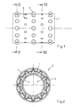
- Fig. 1 shows a heat transfer intermediate tube 1 for a recuperator 2, as he results from FIGS. 2 and 3.
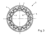
- the recuperator 2 is for a recuperator burner intended. It has an inner tube 3 and an outer tube 4, the intermediate tube 1 the annular space between the inner tube 3 and the outer tube 4 in two concentric, divided essentially annular channels.
- the inner channel is from the Pre-heated combustion air flows through, while the outer duct is exhausted flow through the burner.
- the intermediate tube 1 carries outwardly directed knobs 5 and inwardly Knobs 6, the knobs opposite the heat transfer surface of the intermediate tube enlarge a smooth pipe and thereby increase the efficiency. How 2 and 3 clearly shows, the intermediate tube 1 is at the points of Knobs domed in the shape of a spherical cap, namely outwards for knobs 5 and after Inside for the knobs 6. The wall thickness of the intermediate tube remains 1 constant, so that production using the slip process is easily possible.
- Fig. 1 shows that the knobs 5 and 6 in wreath-shaped Rows are arranged, the wreaths of different Alternate pimples. In addition, the different sit Nubs on gap.
- each constrictions Connect extensions. In the latter form the opposite directed pimples depressions.
- the gases are so alternate on their flow path compressed and expanded. This avoids boundary layer formation, and there are flow conditions that determine the efficiency of the recuperator to that of a rib recuperator Bring steel.
- the entire recuperator consists of silicon infiltrated Silicon carbite (SiSiC).
Landscapes
- Engineering & Computer Science (AREA)
- Physics & Mathematics (AREA)
- Mechanical Engineering (AREA)
- General Engineering & Computer Science (AREA)
- Thermal Sciences (AREA)
- Geometry (AREA)
- Ceramic Engineering (AREA)
- Chemical & Material Sciences (AREA)
- Combustion & Propulsion (AREA)
- Heat-Exchange Devices With Radiators And Conduit Assemblies (AREA)
- Rigid Pipes And Flexible Pipes (AREA)
Claims (9)
- Tube intermédiaire en céramique pour échanger de la chaleur, caractérisé par le fait que la paroi du tube intermédiaire (1) est voûtée, à plusieurs endroits dispersés sur sa longueur et sa circonférence, vers l'extérieur pour former des nopes dirigées vers l'extérieur (5), et vers l'intérieur pour former des nopes dirigées vers l'intérieur (6).
- Tube intermédiaire suivant la revendication 1, caractérisé par le fait que les nopes (5, 6) sont disposées sous forme de couronnes.
- Tube intermédiaire suivant la revendication 2, caractérisé par le fait que dans chaque couronne des nopes dirigées vers l'extérieur alternent avec des nopes dirigées vers l'intérieur.
- Tube intermédiaire suivant la revendication 2, caractérisé par le fait que des couronnes avec des nopes dirigées vers l'extérieur (5) alternent avec des couronnes avec des nopes dirigées vers l'intérieur (6).
- Tube intermédiaire suivant l'une des revendications 1 à 4, caractérisé par le fait que les nopes dirigées vers l'extérieur (5) et les nopes dirigées vers l'intérieur (6) se trouvent à chaque fois sur des génératrices communes du tube intermédiaire (1), ces génératrices alternant les unes avec les autres.
- Tube intermédiaire suivant l'une des revendications 1 à 5, caractérisé par le fait que les nopes (5, 6) sont conçues sous forme de calottes sphériques.
- Récupérateur en céramique, plus particulièrement pour brûleurs autorécupérateurs, avec un tube intérieur (3), un tube extérieur (4) et un tube intermédiaire pour échanger de la chaleur (1) suivant l'une des revendications 1 à 6.
- Récupérateur suivant la revendication 7, caractérisé par le fait que les nopes dirigées vers l'extérieur (5) centrent le tube extérieur (4).
- Récupérateur suivant la revendication 7 ou 8, caractérisé par le fait que les nopes dirigées vers l'intérieur (6) centrent le tube intérieur.
Applications Claiming Priority (2)
| Application Number | Priority Date | Filing Date | Title |
|---|---|---|---|
| DE19616288A DE19616288A1 (de) | 1996-04-24 | 1996-04-24 | Rekuperator aus keramischem Material |
| DE19616288 | 1996-04-24 |
Publications (3)
| Publication Number | Publication Date |
|---|---|
| EP0803696A2 EP0803696A2 (fr) | 1997-10-29 |
| EP0803696A3 EP0803696A3 (fr) | 1999-03-03 |
| EP0803696B1 true EP0803696B1 (fr) | 2000-11-08 |
Family
ID=7792258
Family Applications (1)
| Application Number | Title | Priority Date | Filing Date |
|---|---|---|---|
| EP97105662A Expired - Lifetime EP0803696B1 (fr) | 1996-04-24 | 1997-04-05 | Tube intermédiaire en céramique pour échanger de la chaleur et récupérateur équipé d'un tel tube |
Country Status (3)
| Country | Link |
|---|---|
| EP (1) | EP0803696B1 (fr) |
| AT (1) | ATE197502T1 (fr) |
| DE (2) | DE19616288A1 (fr) |
Cited By (1)
| Publication number | Priority date | Publication date | Assignee | Title |
|---|---|---|---|---|
| EP2378195A1 (fr) | 2010-04-19 | 2011-10-19 | Elster GmbH | Dispositif de montage et dispositif de brûleur |
Families Citing this family (12)
| Publication number | Priority date | Publication date | Assignee | Title |
|---|---|---|---|---|
| ES2161581B1 (es) * | 1998-06-17 | 2002-06-16 | Santaolalla Milla Carlos | Dispositivo para la refrigeracion de liquidos. |
| DE10326951A1 (de) | 2003-06-12 | 2005-01-13 | Aichelin Entwicklungszentrum Und Aggregatebau Gesellschaft Mbh | Rekuperatorbrenner und Rekuperator hierzu |
| EP1697022B1 (fr) * | 2003-12-15 | 2010-02-17 | AGT Thermotechnik GmbH | Dispositif de sechage a froid d'un gaz ou d'un melange gaz-vapeur |
| ITBG20090041A1 (it) * | 2009-07-17 | 2011-01-18 | Esa S R L | Tubo intermedio scambiatore di calore |
| TW201128141A (en) * | 2009-12-16 | 2011-08-16 | Eclipse | Burner with improved heat recuperator |
| DE102011103106A1 (de) | 2011-05-25 | 2012-11-29 | Erbicol S.A. | Wärmeübertrager aus keramischem Material, insbesondere für Rekuperatorbrenner, und Verfahren zu dessen Herstellung |
| DE102011111748A1 (de) * | 2011-08-24 | 2013-02-28 | Karl Stefan Riener | Rauchgas-Luft-Wärmetauscher |
| TR201900614T4 (tr) * | 2014-08-04 | 2019-02-21 | Officine Metallurgiche G Cornaglia S P A | Bir indirgeme çözeltisinin bir motorun tankından egzoz kanalına beslenmesi için ünite. |
| US10465904B2 (en) * | 2017-06-30 | 2019-11-05 | American Air Liquide, Inc. | Furnace with integrated heat recovery utilizing radiative recuperator for preheating combustion reactants using heat from flue gas |
| CN110894944B (zh) * | 2019-11-08 | 2020-10-27 | 西安交通大学 | 一种蛇形通道紊流低温低NOx均匀燃烧燃气装置 |
| WO2022263006A1 (fr) | 2021-06-18 | 2022-12-22 | Schunk Ingenieurkeramik Gmbh | Brûleur récupérateur doté d'un récupérateur destiné à guider des fluides à contre-courant |
| US20240263779A1 (en) | 2021-06-18 | 2024-08-08 | Schunk lngenieurkeramik GmbH | Recuperator burner with a recuperator for guiding counter-flowing fluids |
Family Cites Families (5)
| Publication number | Priority date | Publication date | Assignee | Title |
|---|---|---|---|---|
| DE2742070C2 (de) * | 1977-09-19 | 1982-10-07 | Fa. J. Aichelin, 7015 Korntal | Industriebrenner zur Beheizung von Ofenräumen in Industrieöfen |
| FR2616520B1 (fr) * | 1987-06-11 | 1989-10-27 | Gaz De France | Systeme a bruleur notamment a grande vitesse de sortie des gaz brules |
| DE3915957A1 (de) * | 1989-05-18 | 1990-11-22 | Lbe Beheizungseinrichtungen | Mantelstrahlheizrohr |
| EP0451662B1 (fr) * | 1990-04-11 | 1993-06-16 | Ruhrgas Aktiengesellschaft | Brûleur récupérateur |
| DE19541922C2 (de) * | 1995-11-10 | 1997-11-27 | Ws Waermeprozesstechnik Gmbh | Keramischer Rekuperator für einen Rekuperatorbrenner |
-
1996
- 1996-04-24 DE DE19616288A patent/DE19616288A1/de not_active Withdrawn
-
1997
- 1997-04-05 AT AT97105662T patent/ATE197502T1/de active
- 1997-04-05 EP EP97105662A patent/EP0803696B1/fr not_active Expired - Lifetime
- 1997-04-05 DE DE59702584T patent/DE59702584D1/de not_active Expired - Lifetime
Cited By (2)
| Publication number | Priority date | Publication date | Assignee | Title |
|---|---|---|---|---|
| EP2378195A1 (fr) | 2010-04-19 | 2011-10-19 | Elster GmbH | Dispositif de montage et dispositif de brûleur |
| EP2472180A1 (fr) | 2010-04-19 | 2012-07-04 | Elster GmbH | Dispositif de brûleur |
Also Published As
| Publication number | Publication date |
|---|---|
| EP0803696A2 (fr) | 1997-10-29 |
| ATE197502T1 (de) | 2000-11-11 |
| EP0803696A3 (fr) | 1999-03-03 |
| DE59702584D1 (de) | 2000-12-14 |
| DE19616288A1 (de) | 1997-10-30 |
Similar Documents
| Publication | Publication Date | Title |
|---|---|---|
| DE60015374T2 (de) | Spiralwärmetauscher | |
| EP0544853B1 (fr) | Appareil de chauffage d'air | |
| DE2706728A1 (de) | Waermetauscher fuer einen stirlingmotor, insbesondere fuer kraftfahrzeuge | |
| EP0803696A2 (fr) | Récupérateur en céramique | |
| DE1426648C3 (de) | Schnelldampferzeuger | |
| DE19518331B4 (de) | Mechanisches Rohrdichtungssystem | |
| DE69122818T2 (de) | Statische Dichtung | |
| EP0437825B1 (fr) | Echangeur de chaleur avec plaque d'extrémité et manchon de raccord | |
| DE2306834A1 (de) | Folienblaskopf fuer die herstellung von schlauchfolien | |
| EP0643250B1 (fr) | Assemblage de tuyaux à paroi double | |
| EP0798513B1 (fr) | Elément tubulaire à double paroi pour la fabrication de cheminées | |
| WO2022263006A1 (fr) | Brûleur récupérateur doté d'un récupérateur destiné à guider des fluides à contre-courant | |
| DE3410141C2 (de) | Heizungskessel mit rohrförmigen Heizgaskanälen | |
| DE2217072C3 (de) | Wärmeaustauscher | |
| DE3313422A1 (de) | Rohr mit einer mehrzahl in die rohrwandung eingebrachter verformungsstellen zum einsatz in waermetauschern | |
| EP1076207B1 (fr) | Brûleur à récupération et four associé | |
| EP0711954B1 (fr) | Cheminée d'air/fumée | |
| DE1451259C3 (de) | Wärmeaustauscher | |
| DE10350765A1 (de) | Satz von thermischen Nachverbrennungsvorrichtungen | |
| AT378413B (de) | Extrudiertes hohlkoerperprofil aus kunststoff | |
| DE2324649C2 (de) | Wärmetauscher für motorunabhängige Heizungen in Kraftfahrzeugen | |
| EP0230982B1 (fr) | Echangeur de chaleur cylindrique, fabriqué avec des éléments de construction préfabriqués, en particulier récupérateur sur cheminée | |
| EP0451662B1 (fr) | Brûleur récupérateur | |
| DE4119866C1 (en) | Cast-iron@ boiler made in sections - has inner skin elements with outer flanges and outer skin elements with inner flanges | |
| DE1139601B (de) | Keramischer Rekuperator |
Legal Events
| Date | Code | Title | Description |
|---|---|---|---|
| PUAI | Public reference made under article 153(3) epc to a published international application that has entered the european phase |
Free format text: ORIGINAL CODE: 0009012 |
|
| AK | Designated contracting states |
Kind code of ref document: A2 Designated state(s): AT BE CH DE FR GB IT LI LU |
|
| PUAL | Search report despatched |
Free format text: ORIGINAL CODE: 0009013 |
|
| AK | Designated contracting states |
Kind code of ref document: A3 Designated state(s): AT BE CH DE FR GB IT LI LU |
|
| 17P | Request for examination filed |
Effective date: 19990315 |
|
| RAP1 | Party data changed (applicant data changed or rights of an application transferred) |
Owner name: L B E FEUERUNGSTECHNIK GMBH |
|
| 17Q | First examination report despatched |
Effective date: 20000218 |
|
| GRAG | Despatch of communication of intention to grant |
Free format text: ORIGINAL CODE: EPIDOS AGRA |
|
| GRAG | Despatch of communication of intention to grant |
Free format text: ORIGINAL CODE: EPIDOS AGRA |
|
| GRAH | Despatch of communication of intention to grant a patent |
Free format text: ORIGINAL CODE: EPIDOS IGRA |
|
| RTI1 | Title (correction) |
Free format text: CERAMIC INTERMEDIATE TUBE FOR EXCHANGING HEAT AND RECUPERATOR WITH SUCH A TUBE |
|
| GRAH | Despatch of communication of intention to grant a patent |
Free format text: ORIGINAL CODE: EPIDOS IGRA |
|
| GRAA | (expected) grant |
Free format text: ORIGINAL CODE: 0009210 |
|
| AK | Designated contracting states |
Kind code of ref document: B1 Designated state(s): AT BE CH DE FR GB IT LI LU |
|
| REF | Corresponds to: |
Ref document number: 197502 Country of ref document: AT Date of ref document: 20001111 Kind code of ref document: T |
|
| REG | Reference to a national code |
Ref country code: CH Ref legal event code: EP |
|
| GBT | Gb: translation of ep patent filed (gb section 77(6)(a)/1977) |
Effective date: 20001108 |
|
| ITF | It: translation for a ep patent filed | ||
| REF | Corresponds to: |
Ref document number: 59702584 Country of ref document: DE Date of ref document: 20001214 |
|
| ET | Fr: translation filed | ||
| PGFP | Annual fee paid to national office [announced via postgrant information from national office to epo] |
Ref country code: LU Payment date: 20010402 Year of fee payment: 5 |
|
| PLBE | No opposition filed within time limit |
Free format text: ORIGINAL CODE: 0009261 |
|
| STAA | Information on the status of an ep patent application or granted ep patent |
Free format text: STATUS: NO OPPOSITION FILED WITHIN TIME LIMIT |
|
| 26N | No opposition filed | ||
| REG | Reference to a national code |
Ref country code: GB Ref legal event code: IF02 |
|
| PGFP | Annual fee paid to national office [announced via postgrant information from national office to epo] |
Ref country code: CH Payment date: 20020319 Year of fee payment: 6 |
|
| PG25 | Lapsed in a contracting state [announced via postgrant information from national office to epo] |
Ref country code: LU Free format text: LAPSE BECAUSE OF NON-PAYMENT OF DUE FEES Effective date: 20020405 |
|
| PGFP | Annual fee paid to national office [announced via postgrant information from national office to epo] |
Ref country code: BE Payment date: 20020412 Year of fee payment: 6 |
|
| PG25 | Lapsed in a contracting state [announced via postgrant information from national office to epo] |
Ref country code: LI Free format text: LAPSE BECAUSE OF NON-PAYMENT OF DUE FEES Effective date: 20030430 Ref country code: CH Free format text: LAPSE BECAUSE OF NON-PAYMENT OF DUE FEES Effective date: 20030430 Ref country code: BE Free format text: LAPSE BECAUSE OF NON-PAYMENT OF DUE FEES Effective date: 20030430 |
|
| BERE | Be: lapsed |
Owner name: *LBE FEUERUNGSTECHNIK G.M.B.H. Effective date: 20030430 |
|
| REG | Reference to a national code |
Ref country code: CH Ref legal event code: PL |
|
| REG | Reference to a national code |
Ref country code: GB Ref legal event code: 732E |
|
| REG | Reference to a national code |
Ref country code: FR Ref legal event code: TP |
|
| REG | Reference to a national code |
Ref country code: FR Ref legal event code: PLFP Year of fee payment: 19 |
|
| REG | Reference to a national code |
Ref country code: FR Ref legal event code: PLFP Year of fee payment: 20 |
|
| PGFP | Annual fee paid to national office [announced via postgrant information from national office to epo] |
Ref country code: GB Payment date: 20160421 Year of fee payment: 20 Ref country code: DE Payment date: 20160421 Year of fee payment: 20 |
|
| PGFP | Annual fee paid to national office [announced via postgrant information from national office to epo] |
Ref country code: IT Payment date: 20160427 Year of fee payment: 20 Ref country code: AT Payment date: 20160421 Year of fee payment: 20 Ref country code: FR Payment date: 20160421 Year of fee payment: 20 |
|
| REG | Reference to a national code |
Ref country code: DE Ref legal event code: R071 Ref document number: 59702584 Country of ref document: DE |
|
| REG | Reference to a national code |
Ref country code: GB Ref legal event code: PE20 Expiry date: 20170404 |
|
| REG | Reference to a national code |
Ref country code: AT Ref legal event code: MK07 Ref document number: 197502 Country of ref document: AT Kind code of ref document: T Effective date: 20170405 |
|
| PG25 | Lapsed in a contracting state [announced via postgrant information from national office to epo] |
Ref country code: GB Free format text: LAPSE BECAUSE OF EXPIRATION OF PROTECTION Effective date: 20170404 |