EP0803886B1 - Condensateurs à électrolyte solide comprenant une couche conductrice d'une polymère de pyrrole ou son dérivé, et son procédé de fabrication - Google Patents
Condensateurs à électrolyte solide comprenant une couche conductrice d'une polymère de pyrrole ou son dérivé, et son procédé de fabrication Download PDFInfo
- Publication number
- EP0803886B1 EP0803886B1 EP97302334A EP97302334A EP0803886B1 EP 0803886 B1 EP0803886 B1 EP 0803886B1 EP 97302334 A EP97302334 A EP 97302334A EP 97302334 A EP97302334 A EP 97302334A EP 0803886 B1 EP0803886 B1 EP 0803886B1
- Authority
- EP
- European Patent Office
- Prior art keywords
- conductive polymer
- layer
- capacitor
- dielectric film
- polymer layer
- Prior art date
- Legal status (The legal status is an assumption and is not a legal conclusion. Google has not performed a legal analysis and makes no representation as to the accuracy of the status listed.)
- Expired - Lifetime
Links
Images

Classifications
-
- H—ELECTRICITY
- H01—ELECTRIC ELEMENTS
- H01G—CAPACITORS; CAPACITORS, RECTIFIERS, DETECTORS, SWITCHING DEVICES, LIGHT-SENSITIVE OR TEMPERATURE-SENSITIVE DEVICES OF THE ELECTROLYTIC TYPE
- H01G9/00—Electrolytic capacitors, rectifiers, detectors, switching devices, light-sensitive or temperature-sensitive devices; Processes of their manufacture
- H01G9/004—Details
- H01G9/022—Electrolytes; Absorbents
- H01G9/025—Solid electrolytes
-
- H—ELECTRICITY
- H01—ELECTRIC ELEMENTS
- H01G—CAPACITORS; CAPACITORS, RECTIFIERS, DETECTORS, SWITCHING DEVICES, LIGHT-SENSITIVE OR TEMPERATURE-SENSITIVE DEVICES OF THE ELECTROLYTIC TYPE
- H01G11/00—Hybrid capacitors, i.e. capacitors having different positive and negative electrodes; Electric double-layer [EDL] capacitors; Processes for the manufacture thereof or of parts thereof
- H01G11/22—Electrodes
- H01G11/30—Electrodes characterised by their material
- H01G11/48—Conductive polymers
-
- H—ELECTRICITY
- H01—ELECTRIC ELEMENTS
- H01G—CAPACITORS; CAPACITORS, RECTIFIERS, DETECTORS, SWITCHING DEVICES, LIGHT-SENSITIVE OR TEMPERATURE-SENSITIVE DEVICES OF THE ELECTROLYTIC TYPE
- H01G11/00—Hybrid capacitors, i.e. capacitors having different positive and negative electrodes; Electric double-layer [EDL] capacitors; Processes for the manufacture thereof or of parts thereof
- H01G11/54—Electrolytes
- H01G11/56—Solid electrolytes, e.g. gels; Additives therein
-
- H—ELECTRICITY
- H01—ELECTRIC ELEMENTS
- H01G—CAPACITORS; CAPACITORS, RECTIFIERS, DETECTORS, SWITCHING DEVICES, LIGHT-SENSITIVE OR TEMPERATURE-SENSITIVE DEVICES OF THE ELECTROLYTIC TYPE
- H01G9/00—Electrolytic capacitors, rectifiers, detectors, switching devices, light-sensitive or temperature-sensitive devices; Processes of their manufacture
- H01G9/0029—Processes of manufacture
- H01G9/0036—Formation of the solid electrolyte layer
-
- H—ELECTRICITY
- H01—ELECTRIC ELEMENTS
- H01G—CAPACITORS; CAPACITORS, RECTIFIERS, DETECTORS, SWITCHING DEVICES, LIGHT-SENSITIVE OR TEMPERATURE-SENSITIVE DEVICES OF THE ELECTROLYTIC TYPE
- H01G9/00—Electrolytic capacitors, rectifiers, detectors, switching devices, light-sensitive or temperature-sensitive devices; Processes of their manufacture
- H01G9/004—Details
- H01G9/022—Electrolytes; Absorbents
- H01G9/025—Solid electrolytes
- H01G9/028—Organic semiconducting electrolytes, e.g. TCNQ
-
- H—ELECTRICITY
- H01—ELECTRIC ELEMENTS
- H01G—CAPACITORS; CAPACITORS, RECTIFIERS, DETECTORS, SWITCHING DEVICES, LIGHT-SENSITIVE OR TEMPERATURE-SENSITIVE DEVICES OF THE ELECTROLYTIC TYPE
- H01G9/00—Electrolytic capacitors, rectifiers, detectors, switching devices, light-sensitive or temperature-sensitive devices; Processes of their manufacture
- H01G9/004—Details
- H01G9/04—Electrodes or formation of dielectric layers thereon
- H01G9/042—Electrodes or formation of dielectric layers thereon characterised by the material
- H01G9/0425—Electrodes or formation of dielectric layers thereon characterised by the material specially adapted for cathode
-
- Y—GENERAL TAGGING OF NEW TECHNOLOGICAL DEVELOPMENTS; GENERAL TAGGING OF CROSS-SECTIONAL TECHNOLOGIES SPANNING OVER SEVERAL SECTIONS OF THE IPC; TECHNICAL SUBJECTS COVERED BY FORMER USPC CROSS-REFERENCE ART COLLECTIONS [XRACs] AND DIGESTS
- Y02—TECHNOLOGIES OR APPLICATIONS FOR MITIGATION OR ADAPTATION AGAINST CLIMATE CHANGE
- Y02E—REDUCTION OF GREENHOUSE GAS [GHG] EMISSIONS, RELATED TO ENERGY GENERATION, TRANSMISSION OR DISTRIBUTION
- Y02E60/00—Enabling technologies; Technologies with a potential or indirect contribution to GHG emissions mitigation
- Y02E60/13—Energy storage using capacitors
Definitions
- This invention relates to capacitors which exhibit good capacitor characteristics such as frequency characteristics and dielectric strength characteristics and more particularly, to small-sized, large capacitance, solid electrolytic capacitors of the type which comprises at least one conductive polymer layer doped with a mixed dopant composed of a polyvalent anion and a monovalent anion.
- the invention also relates to a method for making such capacitors as mentioned above.
- capacitors which have been in use in a high frequency range include, for example, plastic capacitors, mica capacitors and layer-built ceramic capacitors.
- plastic capacitors for example, plastic capacitors, mica capacitors and layer-built ceramic capacitors.
- these capacitors are so large in size that it is difficult to realize a great capacitance.
- Capacitors of a large capacitance type include, for example, electrolytic capacitors such as aluminium dry electrolytic capacitors and aluminium or tantalum solid electrolytic capacitors. These capacitors have a very thin oxide film serving as a dielectric and can thus realize a large capacitance. However, such a very thin oxide film is very liable to suffer damages. In order to repair the damages, it is necessary to form an electrolyte layer on the oxide film. The electrolyte layer serves also as a true cathode.
- a liquid electrolyte is used such that anodic and cathodic aluminium foils which have been, respectively, etched on the surfaces thereof are convolutely wound through a separator, in which the liquid electrolyte is impregnated.
- the liquid electrolyte exhibits ionic conductivity and is so great in specific resistance that a great loss is incurred, thereby presenting the problem that the resultant capacitor is great in loss and very poor in frequency characteristics of impedance and temperature characteristics.
- the use of the liquid electrolyte inevitably involves the leakage and evaporation of the electrolyte, coupled with another problem that the capacitor undesirably decreases in capacitance and increase in loss as time passes.
- Tantalum solid electrolytic capacitors make use of a manganese oxide electrolyte and can overcome the problems on the variations of temperature characteristics, capacitance and loss in relation to time.
- the manganese oxide electrolyte is relatively high in specific resistance. This leads to the frequency characteristics of impedance which are poorer than those of layer-built ceramic capacitors or film capacitors.
- the formation of the manganese oxide electrolyte layer essentially requires repetition of several to several tens of cycles of the step of immersion in a manganese nitrate solution and subsequent thermal decomposition at a temperature of about 300°C, thus being complicated in the formation step.
- the electrolyte composed of manganese oxide is formed by repeating the thermal decomposition cycle.
- To repair the film damaged during the repetition of the thermal decomposition cycle requires the formation of a dielectric film after every cycle of the thermal decomposition. This also involves the problem of complicating the procedure.
- a conductive polymer layer is formed by chemical polymerization, it has been found difficult to form the conductive polymer layer at a high packing rate to the depth of irregularities of an etched aluminium foil or to the depth of fine pores of a tantalum sintered body. Additionally, the use of an electrolytically polymerized product having high conductivity may lead to the lowering of the dielectric strength of the resulting capacitor.
- EP-A-0 654 804 describes a solid electrolytic capacitor comprising an anode, a dielectric layer, a solid electrolytic layer and a cathode electrode, wherein the solid electrolytic layer consists of a conductive polymer compound obtained by doping a dopant in one of a copolymer and mixture of a specified polypyrrole derivative thereof and a specified polyaniline or a derivative thereof.
- the dielectric layer is coated with a first conductive polymer layer consisting of polypyrrole doped with a sulfonate ion dissociated from dodecylbenzene ferric sulfonate.
- a solid electrolytic capacitor defined by the features of claim 1. It comprises a pair of electrodes, and a dielectric film provided between the paired electrodes wherein at least one of the paired electrodes is made of a conductive polymer consisting of a member selected from the group consisting of pyrrole and derivatives thereof the conductive polymer being doped with a mixed dopant of a polyvalent anion supplied from an oxidant and a monovalent anion consisting of a sulfonate ion dissociated from an anionic surface active agent.
- the dielectric film may consist of an oxide of the valve metal.
- the dielectric film may be made of a polyimide. If the polyimide dielectric film is used, both electrodes may be made of the conductive polymer although an anode may be made of a valve metal.
- the at least one electrode may be made of such a conductive polymer layer as mentioned above, but should preferably have a double-layered structure or a multi-layered structure which comprises, aside from the conductive polymer layer of pyrrole or its derivative, at least one layer made of a conductive polymer of a thiophene derivative represented by the following general formula wherein A represents an unsubstituted or substituted alkylene group.
- a method for making a solid electrolytic capacitor defined by the features of claim 15. It comprises the steps of providing an electrode, forming a dielectric film on the electrode, and forming a counter electrode on the dielectric film wherein the counter electrode comprises a conductive polymer layer consisting of a polymer of pyrrole or its derivative doped with a mixed dopant comprising a polyvalent anion supplied from an oxidant and a monovalent sulfonate anion dissociated from an anionic surface active agent.
- a solid electrolytic capacitor unit C essentially includes an electrode 10 having a dielectric layer 12 and a solid electrolyte layer 14.
- the solid electrolyte layer 14 is made of a conductive polymer doped with a mixed dopant which consists of a polyvalent anion and a monovalent anion. These essential components are shown as shaded in Fig. 1A.
- the capacitor unit C having the electrode 10, the dielectric layer 12 and the solid electrolyte layer 14 is a minimum and fundamental capacitor unit of the invention.
- the electrode 10 may be made of either a valve metal or a conductive polymer of pyrrole or its derivative as used for the solid electrolyte layer 14.
- the valve metal includes, for example, aluminium or tantalum although other metals such as zirconium, niobium, hafnium, titanium and intermetallic compounds thereof may also be used. Preferably, aluminium or tantalum is used.
- the electrode 10 serves as an anode. If the valve metal is used, the dielectric film 12 is formed by anodization to provide a valve metal oxide, e.g. aluminium oxide or tantalum oxide. On the other hand, if the dielectric film 12 is made of a dielectric polymer such as a polyimide, either a valve metal as mentioned above or a conductive polymer layer may be used as the electrode 10.
- the electrode 10 made of a valve metal may be in the form of a foil, a sheet, or a sintered body.
- the foil or sheet is chemically etched on the surfaces thereof.
- the electrode 10 made of a conductive polymer will be described hereinafter when reference is made to the solid electrolyte layer 14 because the electrode 10 may be the same as the solid electrolyte layer 14 with respect to the composition or the structural arrangement thereof.
- the dielectric film may be made of a valve metal oxide when the electrode 10 is composed of a valve metal such as Al or Ta.
- a polyimide may be likewise used as the dielectric film.
- the polyimide include those which have recurring units of the following formulas (1) to (3) wherein n is an integer sufficient to form a polymer film and, for example,. ranging from several hundreds to several thousands.
- the solid electrolyte layer 14 is made of a conductive polymer of pyrrole or its derivative doped with a mixed dopant composed of a polyvalent anion and a monovalent anion.
- the layer 14 is of the single-layered type.
- the conductive polymer layer 14 serves as a true cathode when the dielectric film is constituted of a valve metal oxide.
- the conductive polymer layer 14 serves merely as a counter electrode.
- the derivatives of pyrrole include, for example, 3, or 3,4-alkyl or aryl pyrroles such as 3-methylpoyrrole, 3-phenylpyrrole, 3-methyl-4-phenylpyrrole and the like, N-substituted pyrroles such as an N-alkylpyrroles such as N-methylpyrrole, substituted N-arylpyrrolees such as nitrophenylpyrrole and the like.
- the mixed dopant comprises both a polyvalent anion and a monovalent anion.
- an anionic surface active agent capable of yielding a monovalent anion for example, in a polymerization system
- the monovalent ions dissociated from the surface active agent are incorporated in the resultant polymer product competitively with a polyvalent anion of an oxidant such as, for example, a salt of a transition metal and a polyvalent acid.
- the polyvalent anions are supplied from the salts of transition metals and polyvalent acids used as an oxidant.
- the transition metals include iron (III), copper (II), chromium (VI), cerium (IV), ruthenium (III) and manganese (VII).
- the polyvalent acids include sulfuric acid, phosphoric acid, chromic acid, bichromic acid and the like.
- Preferred polyvalent anions include sulfate.
- the monovalent anions are those derived from surface active agents and include sulfonates. More preferably, aromatic sulfonates such as alkylnaphthalenesulfonate and dodecylbenzenesulfonate are used. It should be noted that the term "alkylnaphthalenesulfonate” is intended to mean a mixture of alkylnaphthalenesulfonates having alkyl moieties having from 3 to 6 carbon atoms and such an alkylnaphthalenesulfonate is commercially available from Takemoto Oils Co,. Ltd. under the designation of A-43-F.
- the mixed dopant is preferably present in an amount sufficient to provide a given level of electric conductivity and is in the range of 20 to 40 mole% based on the conductive polymer product.
- the ratio by mole between the polyvalent and monovalent anions is preferably in the range of 1:9 to 1:999, more preferably 1:9 to 1:99.
- the solid electrolyte layer 14 made of the doped conductive polymer of pyrrole or its derivative has been described above as a single layer.
- This layer 14 should preferably have a double-layered structure or a multi-layered structure as shown in Fig. 1B. More particularly, the layer 14 may have a double-layered structure including a sub-layer 14a and a sub-layer 14b or a three-layered structure including a sub-layer 14a, and sub-layers 14b and 14c formed on opposite sides of the sub-layer 14a.
- the sub-layer 14a is made of a conductive polymer of pyrrole or its derivative as having set out with respect to the single-layered solid electrolyte layer 14 in Fig. 1A.
- the sub-layer 14b of the double-layered structure is formed in contact with the dielectric layer 12.
- Both sub-layers 14b and 14c are made of a conductive polymer of a thiophene derivative of the following formula wherein A represents an unsubstituted or substituted alkylene group.
- the alkylene group should preferably have 2 to 6 carbon atoms.
- the thiophene derivative is obtained, for example, by reacting an alkali metal of 3,4-dihydroxythiophene-2,5-dicarboxylate with an appropriate alkylene-vic-dihalide, followed by hydrolysis to obtain 3,4-(alkylene-vic-dioxy)thiophene-2,5-carboxylic acid and further decarboxylation (Polymer, Vol. 36, No. 7 (1994), p. 1347; The Tetrahedron, Vol. 23 (1967), p. 2437; and J. Am. Chem. Soc. Vol. 67 (1945), p. 2217).
- the alkylene group which may be substituted includes 1,2-alkylene groups obtained from alpha-olefins such as ethene, 1-propene, 1-hexene and the like. Besides, 1,2-cyclohexene, 2,3-butylene, 2,3-dimethylene, and 2,3-pentylene may also be used. Preferably, methylene, 1,2-ethylene, and ,2-propylene are mentioned.
- the sub-layers 14b and 14c are preferably doped with a dopant comprising at least a monovalent anion. By this, the yield and electric conductivity of the sub-layers 14b and 14c increase.
- the monovalent anions are preferably ones derived from anionic surface active agents which have been defined hereinbefore with respect to the single-layered structure of the solid electrolyte layer 14. More preferably, the monovalent anion consists of a sulfonate dissociated from anionic surface active agents. Alternatively, the sulfonate anions may be a polystyrenesulfonate anion. When using the polystyrenesulfonate anion, the capacitor characteristics and the heat resistance can be improved.
- the polyvalent anions may also be contained in the sub-layers 14b, 14c. If the polyvalent anions are present in an oxidant solution, the monovalent anion such as a sulfonate anion is competitively incorporated in the resultant conductive polymer.
- the polyvalent anions may be those defined with respect to the solid electrolyte layer 14. More particularly, the polyvalent anion should preferably be supplied from salts of transition metals and polyvalent acids as having illustrated with respect to the single-layered structure. Examples of the transition metal include iron (III), copper (II), chromium (VI), cerium (IV), ruthenium (III) and manganese (VII). Examples of the polyvalent adds include sulfuric acid, phosphoric acid, chromic acid, bichromic add and the like. Preferred polyvalent anions include a sulfate anion.
- the dopant which is either in the form of a mixed dopant or a single dopant, in the sub-layers 14b, 14c should preferably be present in an amount of 20 to 40 % by mole based on the conductive polymer composition.
- the mixing ratio by mole between the polyvalent and monovalent anions is preferably in the range of 1:9 to 1:999.
- the capacitor of the present invention may further comprise a manganese oxide layer 16 between the dielectric film 12 and the solid electrolyte layer or conductive polymer layer 14, which is either of the single-layered type or a multi-layered type, as is particularly shown in Fig. 1A.
- the manganese dioxide layer which has a relatively low electric conductivity can lower an increasing rate of leakage current accompanied by an increasing voltage being applied to the capacitor.
- the conductive polymer layer 14 serves as a true electrode, it is usual to form a lead electrode on the layer 14.
- the lead electrode 18 is made, for example, of a carbon layer and a silver paint layer (both not shown) formed by a usual manner with or without a metallic lead (not shown) attached to the silver paint layer.
- the capacitor unit may be covered with a thermosetting resin such as an epoxy resin to protect the unit.
- a thermosetting resin such as an epoxy resin to protect the unit.
- the unit may be encased in an appropriate casing, if necessary.
- the capacitor C including the fundamental arrangement having the electrode 10, the dielectric film 12 and the conductive polymer layer 14 as shown in Fig. 1A can be made by the following method when using a valve metal as the electrode 10.
- the method comprises providing a valve metal piece in the form of a foil, a sheet or a sintered body, anodizing the valve metal piece to form a dielectric film 12 on at least one side of the valve metal piece, and forming a conductive polymer layer 14 on the dielectric film 12 wherein the conductive polymer layer 14 is made of a conductive polymer of pyrrole or its derivative doped with a mixed dopant as defined before.
- the conductive polymer layer 14 should preferably be formed by chemical polymerization of a monomer in a polymerization system although electrolytic polymerization may be used.
- the chemical polymerization proceeds in the vicinity of room temperature. This is advantageous in that the dielectric film, which is either a valve metal oxide or a polyimide film, is prevented from being damaged owing to the application of heat thereto.
- a manganese oxide may be further formed thereon by any known techniques such as thermal decomposition of manganese salts.
- the manganese dioxide layer is formed between the dielectric film and the conductive polymer layer, the resultant solid electrolytic capacitor exhibits only a low leakage current.
- valve metal The anodization of a valve metal may be effected by any known technique. For instance, a valve metal piece is placed in an acidic solution, to which a given potential is applied at an elevated temperature of 70 to 95°C to form a dielectric oxide film on the valve metal piece. As a matter of course, the dielectric film may be formed on one side of the metal piece or may be formed to entirely cover the metal piece therewith.
- the chemical polymerization is conducted to form the conductive polymer layer on the dielectric film. More particularly, the chemical polymerization comprises immersing the dielectric film-bearing valve metal piece in a monomer solution comprising a monomer of pyrrole or its derivative, and an anionic surface active agent capable of yielding a monovalent sulfonate anion for a time of 1 to 60 minutes, further immersing the thus immersed piece in an oxidant solution comprising a salt capable of yielding a polyvalent anion with or without an anionic surface active agent as used above for a time of 2 to 120 minutes, and repeating the above immersion steps until a desired thickness of a doped conductive layer is formed.
- This reaction proceeds at room temperature although higher or lower temperatures may be used.
- the monomer solution comprises 0.05 to 1 mole/liter of the monomer, and 0.1 to 10 wt% of the surface active agent.
- the salt is preferably present in an amount of 0.1 to 1 mole/liter of the oxidant solution and the surface active agent is preferably present in an amount of 0.1 to 1 wt% based on the oxidant solution.
- the immersion steps are usually repeated several to several tens of times whereby the resultant doped conductive layer has a thickness of 1 to 30 ⁇ m.
- a monomer, an anionic surface active agent and an oxidant may be mixed together in an aqueous medium such as water, in which the dielectric film-bearing valve metal piece is dipped or immersed to form a conductive polymer layer. The immersion may be repeated to make a desired thickness, or may be kept over a time sufficient to make a desired thickness.
- the polymerization since the monomer readily contact the oxidant, the polymerization takes place immediately.
- the polymerization system should preferably comprise 0.05 to 1 mole/liter of the monomer, 0.1 to 1 mole/liter of the slat and 0.1 to 10 wt% of the surface active agent.
- the salts serving as an oxidant are preferably ferric sulfate.
- the chemical polymerization in either case is preferably conducted in a medium comprising water and an alcohol although water alone may be used as the medium.
- an alcohol is advantageous in that when a cation such as, for example, a transition metal cation derived from the salt between a transition metal and a polyvalent acid, and the anion derived from an anionic surface active agent are combined to provide a water-insoluble salt, such a salt can be dissolved in the alcohol. This ensures a homogeneous and uniform polymerization solution phase without causing any precipitation.
- the water-insoluble matter may prevent the monomer solution or the polymerization system from quick arrival at the valleys of irregularities of an etched surface of a valve metal electrode having a dielectric film thereon or from entering into the fine pores of a sintered body of a valve metal, thereby lowering the covering rate with a conductive polymer.
- the alcohol examples include methanol, ethanol, propanol, ethylene glycol, propylene glycol, glycerine and mixtures thereof. If an alcohol is present, its content in the polymerization medium is preferably in the range of 2 to 25 wt%.
- the polymerization reaction rate of pyrrole or its derivative can be appropriately controlled depending on the amount of an alcohol in the polymerization reaction system. More particularly, if the amount of an alcohol increases, the polymerization reaction rate can be decreased.
- the presence of an alcohol ensures reliable formation of a conductive polymer layer in the vicinity of a valve metal electrode. If an aqueous medium alone is used, there may arise some problem that the conductive polymer layer is unlikely to be formed to the depth of etching pits of an etched valve metal foil or sheet or to the depth of fine pores in a sintered body of a valve metal. This problem can be solved by use of an alcohol in combination with water in the monomer solution and/or in the oxidant solution, or in the polymerization system comprising all the essential components.
- the chemical polymerization is preferably conducted by immersion in a monomer solution comprising a monomer of pyrrole or its derivative and an anionic surface active agent, and further immersion in an oxidant solution comprising ferric sulfate, followed by repeating the above steps.
- the resultant conductive polymer layer can be formed to the deep sites in the irregularities or fine pores formed by etching of a valve metal foil or sintering of a valve metal piece. A high coverage with the conductive polymer is ensured, thus resulting in a high-capacitance capacitor.
- the surface active agent is anionic in nature, and the monovalent anion dissociated therefrom is taken in the resultant polymer competitively with the polyvalent anion of a salt of a transition metal and a polyvalent acid used as an oxidant.
- the anion of an anionic surface active agent has a hydrophobic group therein and is so large in size that de-doping of the anion as will be otherwise caused under high temperature or high humidity conditions can be effectively suppressed.
- the conductive polymer suffers only a reduced degree of degradation as time passes.
- the capacitor using such a conductive polymer exhibits good heat and moisture resistances.
- the monovalent anion derived from the surface active agent is more likely to be taken in the conductive polymer than the polyvalent anion derived from an oxidant.
- the ratio of the monovalent anion to the mixed dopant depends greatly on the concentration of a surface active agent rather than on the concentration of an oxidant.
- the ratio can be appropriately controlled by changing the concentration of a surface active agent.
- the ratio of the monovalent anion to the mixed dopant is in the range of 9 to 999:1.
- the capacitor using the conductive polymer doped with the mixed dopant is remarkably improved in high frequency characteristics and loss characteristic over those using manganese dioxide or a conductive polymer doped only with a salt of a transition metal and a polyvalent acid.
- the anionic surface active agents should preferably contain an anionic sulfonate group, more preferably an anionic aromatic sulfonate group.
- phenolic compounds When the chemical polymerization is effected, it is preferred to add phenolic compounds to the monomer solution or the polymerization system in an amount of 0.01 to 0.2 moles/liter of the monomer solution.
- the phenolic compound is not incorporated in the resulting conductive polymer as a dopant but contributes to improving the electric conductivity and its stability of the polymer. Presumably, this is because the phenolic compound serves to form a conductive polymer which has higher regularity and, thus, a more developed conjugate length.
- the capacitor using the conductive polymer obtained from a polymerization system to which phenolic compounds are added is improved in initial characteristics and stability thereof.
- phenolic compounds examples include phenol, nitrophenol, cyanophenol, hydroxybenzoic acid, hydroxyphenol, acetophenol and mixtures thereof.
- the method of the invention may further comprise forming a manganese dioxide layer between the dielectric film and the conductive polymer layer.
- the formation of the manganese dioxide layer is well known in the art.
- the manganese dioxide layer may be formed by applying onto the dielectric film an aqueous solution of a manganese salt and thermally decomposing the salt at a temperature of 200 to 350°C to form a manganese dioxide layer in a thickness of 0.03 to 1 ⁇ m.
- Examples of such manganese salts include manganese nitrate, manganese acetate and the like water-soluble salts.
- the manganese dioxide layer is relatively low in electric conductivity, and the presence of a thin manganese dioxide layer between the dielectric film and the conductive polymer layer is effective in reducing a leakage current which may increase by increasing a potential being applied to the capacitor.
- the manganese dioxide layer may be formed on the dielectric film by reduction of a permanganate salt.
- permanganate salt include sodium permanganate, potassium permanganate, lithium permanganate, and the like.
- the method wherein the dielectric film made of a valve metal oxide has is formed has been mainly described hereinabove.
- the dielectric film may be formed by coating a solution of a dielectric polymer and drying the solution to form a thin polymer film.
- a dielectric polymer In the practice of the invention, it is preferred to form a thin polymer film by spin coating the solution.
- Such polymers include, for example, polyimides, polyacrylate, polyphenylene oxide, and the like, of which polyimides are preferred.
- the polyimide thin film can be formed, for example, by providing a dimethylformamide/methanol solution of polyamic acid, for example, of the following formula prepared from biphenyltetracrboxylic acid dihydrate and phenylenediamine, adding triethylamine to prepare a polyamic acid solution for electrodeposition, subjecting an aluminium anode to the electrodeposition in the solution to form a polyamic acid thin film on the anode, and thermally hydrolyzing the film at a high temperature of about 250°C to obtain a polyimide thin film
- a valve metal film or a conductive polymer film may be used as the electrode 10 in Fig. 1A.
- valve metal is used as the electrode 10
- a solution of a polymer is applied onto a valve metal foil or sheet or sintered body and dried to form a thin polymer film, followed by formation of a conductive polymer layer in a manner described above.
- a valve metal foil or a sintered body of a valve metal may be partially or wholly immersed in such a polymer solution to cover the foil or body with a polymer layer, followed by further coverage of a conductive polymer layer on the dielectric thin polymer film.
- the thin polymer film is usually formed in a thickness of 0.05 to 3 ⁇ m.
- the electrode 10 may be made of a conductive polymer film of the type used as the conductive polymer layer 14.
- the conductive polymer film is formed, for example, by the following manner. A conductive polymer film is first formed, for example, by electrolytic polymerization. Subsequently, a solution of a dielectric polymer is prepared and applied onto the thus prepared conductive polymer substrate serving as the electrode 10, followed by further formation of a conductive polymer layer 14 in a manner having set out hereinbefore. In this case, the conductive polymer film serving as the electrode 10 is formed in a thickness of 1 to 50 ⁇ m.
- the method of the invention further comprises, prior to the formation of the conductive polymer layer made of a polymer of pyrrole or its derivative, forming the conductive polymer layer 14b shown in Fig. 1B on the dielectric film wherein the conductive polymer layer 14b is made of a polymer of a thiophene derivative of the afore-indicated formula and doped with a monovalent anion.
- the conductive polymer layer 14b should preferably have a thickness of 0.02 to 1 ⁇ m.
- the formation of the conductive polymer layer 14b is preferably conducted by chemical polymerization of the thiophene derivative monomer in a polymerization system comprising a monovalent anion.
- a monovalent anion is preferably a sulfonate group. More preferably, the sulfonate group is derived from an anionic surface active agent such as dodecylbenzenesulfonate, alkylnaphthalenesulfonate or the like.
- the polymerization system may further comprise a polyvalent anion along with the monovalent anion for the reason having set out before.
- Such polyvalent anions are those described with respect to the conductive polymer layer 14 and include those derived from salts of transition metals such as iron (III), copper (II), chromium (V), cerium (IV), ruthenium (III) and manganese (VII) and polyvalent acids such as sulfuric acid, phosphoric acid, permanganic acid, chromic acid, bichromic acid and the like. Of these, a sulfate anion is preferred. More particularly, the polymerization system should preferably contain ferric sulfate and an anionic surface active agent of the type defined with respect to the conductive polymer layer 14.
- fine precipitates consisting of ferric cation and the anion derived from an anionic surface active agent are temporarily formed on which the molecules of thiophene monomer are adsorbed and polymerized in situ.
- the polymerization reaction whose velocity is liable to delay can be accelerated.
- the chemical polymerization is effected by dipping a dielectric film-bearing electrode 10 in a polymerization system comprising a thiophene derivative, an anionic surface active agent capable of yielding a monovalent sulfonate anion, and a sulfate capable of yielding a polyvalent anion, thereby forming a conductive polymer of the thiophene derivative doped with a mixed dopant.
- the chemical polymerization may be effected by immersing the electrode 10 in a monomer solution comprising a thiophene derivative and an anionic surface active agent, and further immersing in an oxidant solution comprising a compound capable of yielding a polyvalent anion.
- the chemical polymerization may be effected substantially in the same manner as described with reference to the single-layered structure but it is usual not to repeat the immersion steps but keep the electrode in the polymerization system or in the oxidant solution to form a conductive polymer of a thiophene derivative.
- the polymerization system is preferably an aqueous system.
- phenol or its derivative may be contained in amounts which have been described with regard to the single-layered structure.
- phenolic compounds include phenol, nitrophenol, cyanophenol, hydroxybenzoic acid, hydroxyphenol, acetophenol and mixtures thereof.
- the conductive layer 14b may also be formed by dipping a dielectric film-bearing electrode 10 in a solution of a conductive polymer of the thiophene derivative, which has been prepared separately such as by electrolytic polymerization or oxidation polymerization.
- a conductive polymer of the thiophene derivative which has been prepared separately such as by electrolytic polymerization or oxidation polymerization.
- polystyrenesulfonate may be used as a dopant, aside from the anionic surface active agent defined before.
- the conductive polymer layer 14a of pyrrole or its derivative is formed in a manner as having set out with respect to the single-layered conductive polymer layer 14 preferably by chemical polymerization.
- the conductive polymer layer 14a may be formed by electrolytic polymerization after the formation of the conductive polymer layer 14b.
- a monovalent anion and a polyvalent anion is subjected to polymerization reaction by applying a DV potential of about 2.5 V in an aqueous medium wherein the capacitor unit is used as an anode for the electrolytic polymerization, thereby forming the conductive polymer layer 14b.
- an aqueous medium comprising electrolytes such as sulfonates, perchlorates, tetrafluoroborates and the like.
- electrolytes such as sulfonates, perchlorates, tetrafluoroborates and the like.
- phenolic compounds as mentioned before are preferably added in amounts defined before, with similar results being expected.
- the conductive polymer layer 14b which is formed in addition to the conductive polymer layer 14a is advantageous in that because a thiophene derivative monomer is lower in polymerization rate than pyrrole or its derivative, the monomer is polymerized after infiltration into deeper sites, e.g. etched pits or fine pores, of an etched foil or a porous sintered body of a valve metal. Accordingly, a solid electrolytic capacitor which has a high capacitance can be more readily obtained than in the case using a single-layered structure-type conductive polymer layer made of pyrrole or its derivative polymer.
- This method is irrespective of whether or not the electrode 10 is made of a valve metal or a conductive polymer.
- the conductive polymer layer 14c may be further formed on a side of the conductive polymer layer 14a opposite to that on which the conductive polymer layer 14b has been formed.
- This conductive polymer layer 14c can be formed just like the conductive polymer layer 14b. More particularly, the layer 14c may be formed by chemical polymerization or electrolytic polymerization in a manner as having set out with regard to the layer 14b or may be formed by dipping in a conductive polymer solution. Especially, when the layer 14a made of a conductive polymer of pyrrole or its derivative is formed by chemical polymerization, the conductive layer 14c is preferably formed by the dipping or immersion.
- the invention is more particularly described by way of examples. Comparative examples are also described.
- a tantalum sintered body having a size of 2 mm x 1.4 mm x 0.9 mm was immersed in a solution of 5 ml of phosphoric acid in 1000 ml of water and anodized under conditions of a potential of 40 V and a temperature of about 90°C to form a dielectric oxide film thereon.
- This arrangement was regarded as a capacitor and subjected to measurement of a capacitance in the solution for the anodization treatment, revealing that the capacitance was 17 ⁇ F.
- the thus anodized body was immersed in an aqueous monomer solution comprising 0.75 moles/liter of pyrrole monomer and 0.75 wt% of a sodium alkylnaphthalenesulfonate surface active agent (average molecular weight: 338) for 5 minutes, followed by further immersion in an oxidant solution containing 0.75 moles/liter of ferric sulfate and 0.75 wt% of such a surface active agent as used above for 10 minutes.
- aqueous monomer solution comprising 0.75 moles/liter of pyrrole monomer and 0.75 wt% of a sodium alkylnaphthalenesulfonate surface active agent (average molecular weight: 338) for 5 minutes, followed by further immersion in an oxidant solution containing 0.75 moles/liter of ferric sulfate and 0.75 wt% of such a surface active agent as used above for 10 minutes.
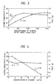
- Fig. 2 shows the electric conductivity and the yield in relation to the variation in concentration of the surface active agent when using a polymerization system comprising 0.375 moles of pyrrole monomer, 0.1 mole/liter of ferric sulfate and 200 ml of an aqueous medium with different amounts of the surface active agent.
- curve A indicates the electric conductivity
- curve B indicates the yield of the doped polypyrrole.
- the elemental analysis revealed that the polymer product was substantially free of any iron ions and that the ratio of sulfur and nitrogen increased with an increasing concentration of the surface active agent.
- the monovalent sulfonate ions from the surface active agent and the divalent sulfate ions were competitively taken in the polymer as a mixed dopant.
- the doping ratio between both types of dopants could have been calculated from the results of the elemental analysis.
- the molar ratio between the sulfate ions and the alkylnaphthalenesulfonate ions in the polypyrrole was found to be 1:29.
- the tantalum sintered body on which the conductive polypyrrole layer had been formed was further formed with a carbon layer and a silver paint layer thereon as an apparent cathode, on which a lead was attached. In this manner, ten capacitor units were made.
- Each unit was fully covered with an epoxy resin and aged by application of a voltage of 13 V under conditions of a temperature of 125°C and a time of 1 hour to complete a capacitor.
- Example 2 16.3 2.7 0.75 -3.0 4.1
- Example 3 4.65 1.7 0.15 -2.0
- Example 4 0.021 1.2 12 - -
- Example 5 16.5 2.4 0.65 -1.2 2.6
- Example 6 (A) 16.4 2.6 0.68 -1.6 3.1 (B) 16.7 2.5 0.72 -1.9 3.2 (C) 16.5 2.7 0.73 -1.8 3.3 (D) 16.7 2.5 0.69 02.0 3.0
- Example 7 16.4 3.2 0.84 -3.5 3.9
- Example 8 16.9 3.5 0.89 - -
- Example 1 For comparison, the general procedure of Example 1 was repeated without use of any sodium alkylnaphthalenesulfonate, thereby obtaining ten capacitors.
- Example 1 The general procedure of Example 1 was repeated using sodium dodecylbenzenesulfonate in place of sodium alkylnaphthalenesulfonate, thereby obtaining 10 capacitors. These capacitors were each subjected to measurements of a capacitance and a loss factor at 1 kHz and an impedance at 400 kHz. Moreover, the variation in capacitance and the loss factor of each capacitor were measured after a loaded heat-resistant test made under conditions of 125°C by application of 10 V. The average values of these measurements are shown in Table 1.
- the thus doped polypyrrole had better electric conductivity and thermal stability than the polypyrrole of Comparative Example 1 doped only with the sulfate ions.
- capacitors which had a high capacitance, a low loss and a good high frequency impedance with a good heat resistance.
- Example 1 The general procedure of Example 1 was repeated using an etched aluminium foil electrode in place of the tantalum sintered body, thereby obtaining ten capacitors. These capacitors were subjected to measurements of characteristic properties in the same manner as in Example 1 with the results shown in Table 1.
- aluminium foil electrode was made in the following manner.
- An aluminium etched foil having a size of 4 mm x 10 mm was partitioned by attachment with a 1 mm wide polyimide tape on opposite sides thereof to make a 3 mm long portion and a 6 mm long portion separated with the polyimide tape.
- An anode lead was attached to the 4 mm wide x 3 mm long portion of the aluminium etched foil.
- the other portion which was 4 mm wide x 6 mm long in size was immersed in an aqueous 3% ammonium adipate solution and anodized at about 70°C by application of 50V to form a dielectric oxide film thereon.
- This arrangement was regarded as a capacitor and subjected to measurement of a capacitance in the anodization solution, revealing that the capacitance was 4.75 ⁇ F.
- Example 3 The general procedure of Example 3 was repeated except that an aluminium foil having a smooth surface and a size of 20 mm x 20 mm was used without any partition thereon and a 0.5 ⁇ m thick polyimide thin film was formed by spin coating without formation of any dielectric oxide film, thereby obtaining 10 capacitors.
- Example 1 The general procedure of Example 1 was repeated except that 0.1 mole/liter of p-nitrophenol was further added to the monomer solution, thereby obtaining ten capacitors. These capacitors were each subjected to measurements of a capacitance and a loss factor at 1 kHz and an impedance at 400 kHz. Moreover, the variation in capacitance and the loss factor of each capacitor were measured after a loaded heat-resistant test performed under conditions of 125°C by application of 10 V. The average values of these measurements are shown in Table 1.
- a polymerization system comprising 0.375 moles/liter of pyrrole monomer, 0.1 mole/liter of ferric sulfate and 0.05 moles/liter of p-nitrophenol and 200 ml of an aqueous medium was mixed with different amounts of sodium alkylnaphthalenesulfonate to determine the electric conductivity and the yield in relation to the variation in the amount of the surface active agent.
- the results are shown in Fig. 3 wherein curve A is for the electric conductivity and curve B is for the yield.
- Example 5 The general procedure of Example 5 was repeated using, in place of p-nitrophenol, p-cyanophenol (A), m-hydroxybenzoic acid (B), m-hydroxyphenol (C), and acetophenol (D), thereby obtaining ten capacitors for each phenol.
- the phenolic derivatives are, respectively, added to the polymerization solution along with the anionic surface active agent, the solution is more likely to be infiltrated into the fine pores of the sintered body in which the polymerization takes place.
- the monovalent anion is doped as being substituted with part of the divalent sulfate ions, thereby leading to a conductive polypyrrole with a more improved electric conductivity.
- the electric conductivity of the polypyrrole is better than that of a conductive polymer doped only with sulfate ions in Comparative Example 1 along with better thermal stability.
- Example 1 The general procedure of Example 1 was repeated using cupric sulfate in place of ferric sulfate at the same concentration, thereby obtaining 10 capacitors. These capacitors were each subjected to measurements of a capacitance and a loss factor at 1 kHz and an impedance at 400 kHz. Moreover, the variation in capacitance and the loss factor of each capacitor were measured after a loaded heat-resistant test performed under conditions of 125°C by application of 10 V. The average values of these measurements are shown in Table 1.
- Example 2 The general procedure of Example 1 was repeated except that after the anodization, the tantalum sintered body was immersed in an aqueous 30% manganese nitrate solution and thermally decomposed at 250°C to form a manganese dioxide layer in a thickness of 0.03 ⁇ m on the dielectric film, thereby obtaining ten capacitors.
- Example 3 The general procedure of Example 3 was repeated except that after the formation of the anodized oxide film on the foil electrode, the foil was immersed in an aqueous 12% sodium permanganate solution, followed by immersion in a solution comprising pyrrole monomer and sodium alkylnaphthalenesulfonate to form a reduced manganese dioxide layer, thereby obtaining capacitors.
- Example 8 Like Example 8, the increasing rate of a leakage current relative to an applied voltage tends to be reduced over the case using the pyrrole layer alone without formation of any manganese dioxide layer.
- a tantalum sintered body having a size of 2 x 1.4 x 0.9 mm was provided and anodized in a solution of 5 ml of phosphoric acid in 1000 ml of water at a temperature of about 90°C by application of 40 V thereby forming a dielectric oxide film thereon.
- This body was immersed in a monomer solution comprising 5 g of pyrrole monomer, 1.6 g of sodium alkylnaphthalenesulfonate (average molecular weight of 338), 90 g of water and 10 g of ethanol, followed by further immersion in an oxidant solution comprising 7.9 g of ferric sulfate hydrate (with a water content of 74%), 1.6 g of the surface active agent of the type used above, and 90 g of water and 10 g of ethanol.
- a monomer solution comprising 5 g of pyrrole monomer, 1.6 g of sodium alkylnaphthalenesulfonate (average molecular weight of 338), 90 g of water and 10 g of ethanol, followed by further immersion in an oxidant solution comprising 7.9 g of ferric sulfate hydrate (with a water content of 74%), 1.6 g of the surface active agent of the type used above, and 90 g of water and 10
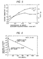
- Fig. 4 shows the electric conductivity and the yield of the doped polypyrrole obtained by polymerization at 25°C for 15 minutes in relation to the variation in content of ethanol in the medium composed of water and ethanol.
- curve A is for the electric conductivity
- curve B is for the yield.
- the yield of the polypyrrole decreases depending of the concentration of ethanol in the medium. On the other hand, little change took place in the electric conductivity when the concentration of ethanol changed.
- Fig. 5 shows the electric conductivity and the yield of polypyrrole obtained by polymerization in a medium composed of 10% by weight of ethanol and the balance of water at 25°C for 1 hour while changing the amount of sodium alkylnaphthalenesulfonate.
- curve A is for the electric conductivity
- curve B is for the yield.
- the addition of the surface active agent results in the increase in the yield and the electric conductivity of the polypyrrole, revealing that the monovalent alkylnaphthalenesulfonate ions are doped.
- Fig. 6 shows the influence of the sodium alkylnaphthalenesulfonate on the stability of electric conductivity when polypyrrole products with or without addition of sodium alkylnaphthalenesulfonate in the polymerization system were maintained in air at 125°C.
- the figure reveals that the electric conductivity of the polypyrrole obtained by addition of the surface active agent is drastically improved over that of the polypyrrole obtained without addition of any surface active agent.
- the elemental analysis of the doped pyrrole obtained in this example reveals that the pyrrole is substantially free of any iron and the ratio of sulfur and nitrogen in the polypyrrole increases with the increase of the yield.
- the polypyrrole layer-bearing tantalum sintered body was further formed thereon with a carbon layer and a silver paint layer to form an apparent cathode on the conductive polypyrrole layer serving as a true cathode.
- a lead was attached to the cathode to obtain ten capacitor units.
- Each unit was covered with an epoxy resin and aged at 125°C by application of 13 V for 60 minutes to complete ten solid electrolytic capacitors.
- Example 10 For comparison, the general procedure of Example 10 was repeated except that ethanol was not added and water was used wholly as the polymerization medium, thereby obtaining ten capacitors. In this case, eleven repetition cycles of the polymerization step were necessary for the formation of the polypyrrole conductive layer.
- Example 10 The general procedure of Example 10 was repeated without use of sodium alkylnaphthalenesulfonate, thereby obtaining 10 capacitors.
- the polymerization rate was appropriately delayed, so that the monomer was more likely to be infiltrated into the sintered body by the action of the sulfonate surface active agent, thereby permitting a polypyrrole layer to be formed to the depth of the fine pores of the sintered body or to the depth of etching pits of an etched aluminium foil.
- the monovalent anion was doped as being substituted with part of the sulfate ions in the polypyrrole conductive layer.
- the capacitor of Example 10 is low in loss and excellent in high frequency impedance characteristic along with a good heat resistance.
- Example 10 In order to attain such a high level of capacitance as in Example 10, it is effective to lower the concentrations of pyrrole monomer and an oxidant, but this may require a greater number of repetition cycles necessary for the formation of a polypyrrole conductive layer.
- Example 10 The general procedure of Example 10 was repeated using, in place of ethanol, methanol (A), n-propanol (B), ethylene glycol (C), propylene glycol (D), and glycerine (E), thereby obtaining ten capacitors for each alcohol. These capacitors were each subjected to measurements of a capacitance and a loss factor at 1 kHz and an impedance at 400 kHz. The average values of these measurements are shown in Table 2.
- Example 11 in Table 2 when these alcohols are added to the polymerization medium, the polymerization rate is appropriately delayed.
- the use of the sulfonate surface active agent improves the capability of infiltration of the monomer into the sintered body, so that it becomes easy to form a conductive polypyrrole layer to the depth of the fine pores of the sintered body.
- the capacitors of Example 11 exhibit a high capacitance, a low loss and a good high frequency impedance characteristic along with a good heat resistance.
- Example 10 The general procedure of Example 10 was repeated using 1.7 g of sodium dodecylbenzenesulfonate in place of the sodium alkylnaphthalenesulfonate, thereby obtaining ten capacitors. These capacitors were each subjected to measurements of a capacitance and a loss factor at 1 kHz and an impedance at 400 kHz. Moreover, the variation in capacitance and the loss factor of each capacitor were measured after a loaded heat-resistant test performed under conditions of 125°C by application of 10 V. The average values of these measurements are shown in Table 2.
- Example 10 The general procedure of Example 10 was repeated using an etched aluminium foil electrode in place of the tantalum sintered body, thereby obtaining ten capacitors. These capacitors were evaluated in the same manner as in Example 10 with the results shown in Table 2.
- the aluminium foil electrode was made in the following manner.
- An aluminium etched foil having a size of 4 mm x 10 mm was partitioned by attachment with a 1 mm wide polyimide tape on opposite sides thereof to make a 3 mm long portion and a 6 mm long portion through the polyimide tape.
- An anode lead was attached to the 4 mm wide x 3 mm long portion of the aluminium etched foil.
- the other portion which was 4 mm wide x 6 mm long in size was immersed in an aqueous 3% ammonium adipate solution and anodized at about 70°C by application of 50V to form a dielectric oxide film thereon.
- This arrangement was regarded as a capacitor and subjected to measurement of a capacitance in the anodization solution, revealing that the capacitance was 4.75 ⁇ F.
- Example 13 good results similar to those of Example 10 are obtained. More particularly, the conductive polypyrrole is better in electric conductivity and its stability than a conductive polypyrrole product doped only with sulfate ions.
- the resultant capacitor has a high capacitance, a low loss and a good high frequency impedance characteristic along with a good heat resistance.
- Example 13 The general procedure of Example 13 was repeated expect that an aluminium smooth foil having a size of 20 mm x 20 mm was used and a 0.5 ⁇ m thick polyimide thin film was formed on the foil by spin coating, thereby obtaining ten capacitors. These capacitors were evaluated in the same manner as in Example 13, with good result shown in Table 2.
- Example 10 The general procedure of Example 10 was repeated except that 0.1 mole/liter of p-nitrophenol was added to the monomer solution, thereby obtaining ten capacitors. These capacitors were each subjected to measurements of a capacitance and a loss factor at 1 kHz and an impedance at 400 kHz. The average values of these measurements are shown in Table 2.
- Example 15 The general procedure of Example 15 was repeated using, in place of p-nitrophenol, m-nitrophenol (A), p-cyanophenol (B), m-hydroxybenzoic acid (C), m-hydroxyphenol (D) and acetophenol (E), thereby obtaining ten capacitors for each phenol.
- Example 10 The general procedure of Example 10 was repeated using cupric sulfate in place of ferric sulfate, thereby obtaining ten capacitors. These capacitors were evaluated in the same manner as in Example 1, with the results shown in Table 2. The results reveal that similar results as in Example 10 were obtained.
- Example 10 The general procedure of Example 10 was repeated except that after completion of the anodization, the tantalum sintered body was immersed in an aqueous 30% manganese nitrate solution and thermally decomposed at 250°C to form a 0.03 ⁇ m thick manganese dioxide layer on the dielectric film, thereby obtaining ten capacitors.
- the capacitors were each subjected to measurements of a capacitance and a loss factor at 1 kHz and an impedance at 400 kHz. The average values of these measurements are shown in Table 2.
- Example 13 The general procedure of Example 13 was repeated except that after the formation of the anodized oxide film on the foil, the foil was immersed in an aqueous 12% sodium permanganate solution, followed by further immersion in a solution comprising pyrrole monomer and sodium alkylnaphthalenesulfonate to form a reduced manganese oxide layer, thereby obtaining ten capacitors.
- the concentration of an alcohol was 10%, a higher or lower concentration may also be used provided that a significant difference in capacitor characteristics develops. It should be noted that if the concentration of an alcohol is too low, there is substantially no difference in polymerization rate from that of the case using water alone as a polymerization medium. On the other hand, if too high a concentration, it takes a long time for the polymerization reaction, thus being poor in economy.
- transition metals used in the examples include iron (III) and copper (II), other types of transition metals having an oxidation-reduction potential capable of oxidizing pyrrole or its derivative. These other types of transition metals are those defined before.
- a polyimide was used as a dielectric polymer.
- Other types of polymers capable of forming a thin dielectric film can be used.
- such a polymer film can be formed by spin coating on an aluminium smooth foil.
- a polymer film may be formed on an etched aluminium foil by electrodeposition.
- the formation of the polymer film is not critical in the practice of the invention.
- anionic surface active agents contributes to improving the capability of infiltration of a monomer or an oxidant to attain a high capacitance capacitor.
- the doping of a monovalent anion having a large-sized molecule also contributes to improving the electric conductivity and its thermal stability of the resultant conductive polymer. This leads to a capacitor whose loss factor and impedance characteristic are excellent, along with a good heat resistance.
- the formation of a manganese dioxide layer between a dielectric film and a conductive polymer layer is effective in improving the loss factor while keeping only a small loss factor.
- the conductive polymer layer having a single-layered structure has been described.
- a conductive polymer layer having a double-layered or multi-layered structure is particularly described
- a tantalum sintered body having a size of 2 mm x 1.4 mm x 0.9 mm was immersed in a solution of 5 ml of phosphoric acid in 1000 ml of water and anodized under conditions of a potential of 40 V and a temperature of about 90°C to form a dielectric oxide film thereon.
- This arrangement was regarded as a capacitor and subjected to measurement of a capacitance in the anodization solution , revealing that the capacitance was 18.0 ⁇ F.
- the thus anodized body was immersed in an aqueous monomer solution comprising 0.1 mole/liter of ethylenedioxythiophene (EDOT) monomer and 0.75 wt% of a sodium alkylnaphthalenesulfonate surface active agent (average molecular weight: 338) for 5 minutes, followed by further immersion in an oxidant solution containing 0.75 moles/liter of ferric sulfate for 60 minutes at 65°C.
- EDOT ethylenedioxythiophene
- EDOT used above was one commercially available from Bayer AG. of Germany although this compound could be prepared by a usual manner.
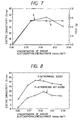
- Fig. 7 shows the electric conductivity and the yield of PEDOT while changing the amount of sodium alkylnaphthalenesulfonate.
- PEDOT was prepared using a monomer solution comprising 0.05 moles of ethylenedioxyethiophene, 0.1 mole of Fe 2 (SO 4 ) 3 and 200 ml of water as a polymerization medium under conditions of 45°C and 20 hours while changing the amount of sodium alkylnaphthalenesulfonate.
- curve A is for the electric conductivity
- curve B is for the yield.
- the yield and the electric conductivity increase by increasing the amount of sodium alkylnaphthalenesulfonate to a certain level.
- the PEDOT layer-bearing tantalum sintered body was immersed in a monomer aqueous solution comprising 0.75 moles/liter of pyrrole monomer and 0.75 wt% of sodium alkylnaphthalenesulfonate (average molecular weight: 338) for 2 minutes, followed by further immersion in such an oxidant solution as used for the formation of PEDOT at 25°C for 10 minutes.
- a monomer aqueous solution comprising 0.75 moles/liter of pyrrole monomer and 0.75 wt% of sodium alkylnaphthalenesulfonate (average molecular weight: 338) for 2 minutes, followed by further immersion in such an oxidant solution as used for the formation of PEDOT at 25°C for 10 minutes.
- the yield and the electric conductivity of the polypyrrole increased by gradual increase in amount of the sodium alkylnaphthalenesulfonate. This is considered to result from the doping of the monovalent sodium alkylnaphthalenesulfonate in the polypyrrole.
- the sulfonate having the surface activity is effective in increasing both the polymerization rate and the yield not only with PEDOT, but also with polypyrrole.
- the elemental analysis of the polypyrrole reveals that the product is substantially free of any iron component.
- the polypyrrole layer was then attached with a carbon layer and a silver paint layer to form an apparent cathode, on which a lead was attached to obtain ten capacitor units.
- the capacitor units were each covered with an epoxy resin and aged at 125°C by application of 13V to complete capacitors.
- Example 25 17.7 2.4 0.069 -2.8 3.1
- Example 26 (A) 17.5 2.5 0.070 -3.0 2.9 (B) 17.6 2.5 0.072 -3.3 3.1 (C) 17.4 2.4 0.071 -3.5 2.9 (D) 17.6 2.4 0.072 -2.9 3.0
- Example 27 17.5 3.5 0.088 -4.5 3.9
- Example 28 4.87 2.3 0.18 -3.7 2.9 Reference 4 4.23 2.8 0.28 -3.9 3.5
- Comp. Ex. 9 3.54 3.3 0.35 -75 80
- Example 29 4.89 1.9 0.17 -3.1 2.4
- Example 30 17.2 3.2 0.087 -4.2 4.2
- Example 31 17.5 3.2 0.084 -4.6 3.9
- Example 20 The general procedure of Example 20 was repeated using, in place of EDOT, 3,4-(1,2-propylene)dioxythiophene (PDOT), thereby forming a conductive poly(3,4-(1,2-propylene)dioxythiophene) (PPDOT), thereby obtaining ten capacitor.
- PDOT 3,4-(1,2-propylene)dioxythiophene
- PPDOT conductive poly(3,4-(1,2-propylene)dioxythiophene)
- each capacitor was subjected to measurements of a capacitance and a loss at 1 kHz and an impedance at 400 kHz. Moreover, each capacitor was subjected to a loaded heat-resistant test by application of 10 V at 125°C over 1000 hours, after which its variation in capacitance and the loss factor were measured. The average values of these measurements are shown in Table 3.
- the conductive PPDOT layer having similar physical properties as the PEDOT layer was formed to provide a composite layer with the polypyrrole layer, and the monovalent anion having the surface activity was doped in the PPDOT layer by partial substitution with the divalent sulfate ions.
- the capacitor had a high capacitance, a low loss factor, a good high frequency impedance along with a good heat resistance.
- Example 20 The general procedure of Example 20 was repeated without formation of any polypyrrole layer but wherein the procedure of forming the PEDOT layer was repeated, thereby ten capacitors.
- the procedure was repeated 30 times to form the PEDOT layer in a thickness of 10 ⁇ m.
- each capacitor was subjected to measurements of a capacitance and a loss at 1 kHz and an impedance at 400 kHz. Moreover, each capacitor was subjected to a loaded heat-resistant test by application of 10 V at 125°C over 1000 hours, after which its variation in capacitance and the loss factor were measured. The average values of these measurements are shown in Table 3.
- Example 20 The comparison between the results of Example 20 and this comparative example reveals that the capacitor characteristics and the heat resistance are similar to each other, but the a greater number of repeated procedures are necessary for the formation of the conductive layer. More particularly, in order to ensure capacitor characteristics and the durability similar to those of Example 20, a longer time is necessary for the formation of the conductive layer, thus being unsatisfactory in practical applications.
- the composite layer composed of the PEDOT layer and the polypyrrole is effective in efficiently manufacturing a capacitor having good capacitor characteristics and a good heat resistance.
- Example 20 The general procedure of Example 20 was repeated without use of any sodium alkylnaphthalenesulfonate in both PEDOT and polypyrrole layers, thereby obtaining ten capacitors.
- each capacitor was subjected to measurements of a capacitance and a loss at 1 kHz and an impedance at 400 kHz. Moreover, each capacitor was subjected to a loaded heat-resistant test by application of 10 V at 125°C over 1000 hours, after which its variation in capacitance and the loss factor were measured. The average values of these measurements are shown in Table 3.
- Example 20 The comparison between the results of Example 20 and this comparative example reveals that the capacitor characteristics and the heat resistance of the capacitor of the comparative example were much poorer than those of Example 20.
- Example 20 sodium alkylnaphthalenesulfonate serving as a surface active agent is used, so that the resultant capacitor is much better than the capacitor of Comparative Example 4 making use of no surface active agent with respect to the capacitor characteristics and the heat resistance.
- this layer was formed only to an extent that the layer was not visually observed on the dielectric film. More particularly, the PEDOT layer was not so formed as to improve the capacitor characteristics and the heat resistance.
- the use of the monovalent alkylnaphthalenesulfonate ions improves not only the yield and the electric conductivity of both the PEDOT layer and the polypyrrole layer, but also the capacitor characteristics and the heat resistance.
- Example 20 The general procedure of Example 20 was repeated without formation of any PEDOT layer but with the polypyrrole layer being formed under the same conditions as in Example 20, thereby obtaining ten capacitors.
- each capacitor was subjected to measurements of a capacitance and a loss at 1 kHz and an impedance at 400 kHz. Moreover, each capacitor was subjected to a loaded heat-resistant test by application of 10 V at 125°C over 1000 hours, after which its variation in capacitance and the loss factor were measured. The average values of these measurements are shown in Table 3.
- Example 20 The comparison between Example 20 and Reference 2 reveals that the capacitance tends to be smaller in Reference 2. This is considered for the reason: because the polymerization rate of pyrrole is so great that the monomer starts to polymerize prior to arrival at the inside of the fine pores in the sintered body, thereby clogging part of the fine pores with the resultant polypyrrole.
- the resultant capacitor which is better in capacitor characteristics and heat resistance can be efficiently fabricated.
- the polymer is formed directly on the dielectric film as in Example 20, the polymer is formed as being infiltrated into deeper sites in the sintered body having the dielectric film thereon without clogging the fine pores therewith.
- the resultant capacitor has an increased capacitance.
- Example 20 The general procedure of Example 20 was repeated except that sodium dodecylbenzenesulfonate was used in place of sodium alkylnaphthalenesulfonate, thereby obtaining ten capacitors.
- each capacitor was subjected to measurements of a capacitance and a loss at 1 kHz and an impedance at 400 kHz. Moreover, each capacitor was subjected to a loaded heat-resistant test by application of 10 V at 125°C over 1000 hours, after which its variation in capacitance and the loss factor were measured. The average values of these measurements are shown in Table 3.
- Example 20 The general procedure of Example 20 was repeated using an etched aluminium foil in place of the tantalum sintered product, thereby obtaining ten capacitors. These capacitors were evaluated in the same manner as in Example 20.
- the etched aluminium foil serving as an electrode was made in the following manner.
- An aluminium etched foil having a size of 4 mm x 10 mm was partitioned by attachment thereon with a 1 mm wide polyimide tape over opposite sides thereof to make a 3 mm long portion and a 6 mm long portion through the polyimide tape.
- An anode lead was attached to the 4 mm wide x 3 mm long portion of the aluminium etched foil.
- the other portion which was 4 mm wide x 6 mm long in size was immersed in an aqueous 3% ammonium adipate solution and anodized at about 70°C by application of 50V to form a dielectric oxide film thereon.
- Example 23 The general procedure of Example 23 was repeated except that any polypyrrole layer was not formed but the procedure of forming the PEDOT layer was repeated until a thickness of 10 ⁇ m was attained, thereby obtaining ten capacitors.
- the repetition cycles were 27 necessary for the formation of the PEDOT layer.
- each capacitor was subjected to measurements of a capacitance and a loss at 1 kHz and an impedance at 400 kHz. Moreover, each capacitor was subjected to a loaded heat-resistant test by application of 10 V at 125°C over 1000 hours, after which its variation in capacitance and the loss factor were measured. The average values of these measurements are shown in Table 3.
- Example 23 The comparison between the results of Example 23 and Comparative Example 5 reveals that the capacitor characteristics and the heat resistance are similar to each other, but a greater number of repeated procedures were necessary for the formation of the PEDOT layer in order to attain similar characteristic properties.
- Example 23 The general procedure of Example 23 was repeated without use of sodium alkylnaphthalenesulfonate in both PEDOT and polypyrrole layers, thereby obtaining ten capacitors.
- each capacitor was subjected to measurements of a capacitance and a loss at 1 kHz and an impedance at 400 kHz. Moreover, each capacitor was subjected to a loaded heat-resistant test by application of 10 V at 125°C over 1000 hours, after which its variation in capacitance and the loss factor were measured. The average values of these measurements are shown in Table 3.
- Example 23 The comparison between the results of Example 23 and this comparative example reveals that the capacitor characteristics and the heat resistance of the capacitor of the comparative example were much poorer than those of Example 23.
- Example 23 since sodium alkylnaphthalenesulfonate serving as a surface active agent was used in Example 23, a great difference results in the capacitor characteristics and the heat resistance in comparison with Comparative Example 6.
- the PEDOT layer was formed only to an extent that the layer is not visually observed on the dielectric film. More particularly, the PEDOT layer was not so formed as to improve the capacitor characteristics and the heat resistance.
- the use of the monovalent alkylnaphthalenesulfonate ions improves not only the yield and the electric conductivity of both the PEDOT layer and the polypyrrole layer, but also the capacitor characteristics and the heat resistance.
- Example 23 The general procedure of Example 23 was repeated without formation of any PEDOT layer, but with the polypyrrole layer being formed under the same conditions as in Example 23, thereby obtaining ten capacitors.
- each capacitor was subjected to measurements of a capacitance and a loss at 1 kHz and an impedance at 400 kHz. Moreover, each capacitor was subjected to a loaded heat-resistant test by application of 10 V at 125°C over 1000 hours, after which its variation in capacitance and the loss factor were measured. The average values of these measurements are shown in Table 3.
- Example 23 The comparison between Example 23 and Reference 3 reveals that the capacitance tends to be smaller in Reference 3. This is considered for the reason: because the polymerization rate of pyrrole is so great that the monomer starts to polymerize prior to arrival at the depth of fine pore in the sintered body, thereby clogging part of the fine pores with the resultant polypyrrole.
- the resultant capacitor which is better in capacitor characteristics and heat resistance can be efficiently fabricated.
- the monovalent alkylnaphthalenesulfonate ions are doped in the built-up conductive layer, not only the yield and the electric conductivity of the PEDOT layer and the polypyrrole layer increase, but also the resultant capacitor is improved in the capacitor characteristics and the heat resistance. Moreover, these characteristic properties can be further improved owing to the surface activity of the sodium alkylnaphthalenesulfonate.
- the PEDOT layer is formed directly on the etched surface on which the dielectric film has been formed, the layer is in intimate contact with the etched aluminium foil, thereby increasing the capacitance.
- Example 23 The general procedure of Example 23 was repeated except that an aluminium smooth foil having a size of 20 mm x 20 mm was used in place of the etched aluminium foil, and that a 0.5 ⁇ m thick polyimide thin film was formed by spin coating in place of the anodized oxide film, thereby obtaining ten capacitors.
- Example 24 The general procedure of Example 24 was repeated without formation of any polypyrrole layer but with the PEDOT layer being formed by repeating the procedure of forming the layer, thereby obtaining ten capacitors.
- the immersion procedure of forming the PEDOT layer was repeated 22 times.
- each capacitor was subjected to measurements of a capacitance and a loss at 1 kHz and an impedance at 400 kHz. Moreover, each capacitor was subjected to a loaded heat-resistant test by application of 10 V at 125°C over 1000 hours, after which its variation in capacitance and the loss factor were measured. The average values of these measurements are shown in Table 3.
- Example 24 The comparison between the results of Example 24 and Comparative Example 7 reveal that the capacitor characteristics and the heat resistance are similar to each other but the PEDOT layer had to be formed by repeating the immersion procedure in a greater number.
- Example 24 The general procedure of Example 24 was repeated without addition of any sodium naphthalenesulfonate, thereby obtaining ten capacitors.
- each capacitor was subjected to measurements of a capacitance and a loss at 1 kHz and an impedance at 400 kHz. Moreover, each capacitor was subjected to a loaded heat-resistant test by application of 10 V at 125°C over 1000 hours, after which its variation in capacitance and the loss factor were measured. The average values of these measurements are shown in Table 3.
- Example 24 The comparison between the results of Example 24 and this comparative example reveals that the heat resistance is very low in the comparative example.
- Example 24 the polyimide film was formed but other types of dielectric polymer films may also be used. Moreover, the formation of the polyimide film may be possible not only by spin coating, but also by electrodeposition on an etched aluminium film.
- Example 20 The general procedure of Example 20 was repeated except that 0.05 moles/liter of p-nitrophenol was further added to the oxidant solution for the formation of both PEDOT and polypyrrole layers, thereby obtaining ten capacitors.
- Fig. 8 shows the relation between the electric conductivity and the content of sodium alkylnaphthalenesulfonate for the preparation of conductive polypyrrole for the presence and absence of p-nitrophenol. This figure reveals that the electric conductivity is greater when p-nitrophenol was added. The elemental analysis reveals that any change was observed in the composition of the polypyrrole obtained by addition of polypyrrole, so that the p-nitrophenol was not taken in as a dopant.
- the electric conductivity of the resultant PEDOT was not clearly improved by the addition of p-nitrophenol, unlike the polypyrrole. However, it was confirmed that polymerization rate was more accelerated to an extent that fine pores in the sintered body were not clogged with the resultant polymer.
- the capacitor of this example is similar in capacitor characteristics and heat resistance to those capacitors of Examples 20 and 21.
- Example 25 The general procedure of Example 25 was repeated using, in place of p-nitrophenol, p--cyanophenol (A), m-hydroxybenzoic acid (B), m-hydroxyphenol (C), and m-nitrophenol (D), thereby obtaining ten capacitors for each phenol.
- Example 20 The general procedure of Example 20 was repeated using cupric sulfate in place of ferric sulfate at the same concentration used in example 20, thereby obtaining ten capacitors.
- the capacitor of this example is slightly inferior in capacitor characteristics and heat resistance to that of Example 20 but is practically acceptable.
- Example 23 The general procedure of Example 23 was repeated wherein polypyrrole was electrolytically polymerized, not chemically polymerized, thereby obtaining ten capacitors.
- the electrolytic polymerization was effected in an aqueous solution comprising 0.25 mole/liter of pyrrole monomer and 0.1 mole/liter of sodium alkylnaphthalenesulfonate serving as a supporting electrolyte. More particularly, after formation of the PEDOT layer, the PEDOT layer-bearing portion was immersed in the aqueous solution and was brought into contact with a stainless steel electrode for electrolytic polymerization. A counter electrode for the electrolytic polymerization was placed away from the first-mentioned electrode. A potential of 2.5 V was applied between the electrodes to form an electrolytically polymerized polypyrrole layer through the PEDOT layer.
- the PEDOT layer was formed by only one immersion procedure, through which the polypyrrole was built up by the electrolytic polymerization.
- a thermally decomposed manganese dioxide layer as a conductive layer on the dielectric film, there can be obtained a capacitor, which has only a small leakage current, without repainting the dielectric film by chemical conversion treatment prior to the electrolytic polymerization.
- the leakage current two minutes after application of 10 V to the capacitor of this example was found to be 15 nA on average.
- Example 28 The general procedure of Example 28 was repeated wherein after formation of the dielectric film, the foil was immersed in an aqueous 30% manganese nitrate solution and thermally decomposed at 250°C, followed by repairing the dielectric film by immersion in an aqueous 3% ammonium adipate solution at about 70°C by application of 40V without formation of any PEDOT layer, thereby completing ten capacitors.
- the capacitors were subjected to measurement of leakage current in a manner similar to Example 28, revealing that the current was 37 nA.
- Example 28 The comparison between the results of Example 28 and this reference reveals that the capacitor characteristics and heat resistance of the capacitor of the reference are slightly inferior to those of the example although the dielectric film was chemically repaired.
- the procedure of Example 28 is advantageous in that the capacitor obtained in Example 28 is high in capacitance and low in loss and has good high frequency impedance and good leakage current characteristic along with a good heat resistance, and repairing of the dielectric film is not necessary, thus the fabrication of the capacitor being very efficient.
- Example 28 The general procedure of Example 28 was repeated except that sodium perchlorate was used in place of sodium alkylnaphthalenesulfonate at the time of the electrolytic polymerization, thereby obtaining ten capacitors.
- Example 28 The comparison between the results of Example 28 and this comparative example reveals that the capacitor of the comparative example is much inferior in capacitor characteristics and heat resistance to the capacitor of Example 28. This is considered for the reason that sodium perchlorate does not significantly contribute to imparting electric conductivity to the resultant polymer, is not bulky and has no surface activity. Accordingly, sodium perchlorate does not permit the monomer to be satisfactorily infiltrated into etched pits, leading to the lowering of capacitance.
- Example 28 The general procedure of Example 28 was repeated except that 0.05 moles/liter of p-nitrophenol was added to the electrolytic polymerization solution, thereby obtaining ten capacitors.
- the capacitor of this example is further improved in capacitor characteristics and heat resistance over that of Example 28. This is considered owing to the co-existence of p-nitrophenol in the polymerization system, by which the initial electric conductivity and environmental stability of the electrolytically polymerized product are further improved.
- Example 20 The general procedure of Example 20 was repeated except that the PEDOT layer was not formed by chemical polymerization, but the anodized tantalum sintered body was immersed in a solution of 0.2 wt% of PEDOT doped with polystyrenesulfonate ions, to which 0.2% of sodium alkylnaphthalenesulfonate was added, at room temperature for 5 minutes, followed by drying at 105°C for 15 minutes, thereby obtaining ten capacitors.
- the PEDOT product doped with polystyrenesulfonate ions was prepared by electrolytic polymerization of EDOT using a polystyrenesulfonate as a supporting electrolyte.
- PEDOT may be prepared by oxidation polymerization of EDOT by use of an oxidant containing a polyvalent anion, e.g. ferric sulfate, in co-existence of a polystyrenesulfonate.
- an oxidant containing a polyvalent anion e.g. ferric sulfate
- polystyrenesulfonate ions are bulky and play substantially the same role as the alkylnaphthalenesulfonate anion derived from sodium alkylnaphthalenesulfonate which is an aromatic sulfonate surface active agent.
- thiophene derivatives of the afore-indicated formula may be likewise used if the resultant PEDOT's are soluble in a liquid medium.
- Sulfonate anions other than polystyrenesulfonates ions may be likewise used for the doping provided that they are bulky.
- Such sulfonate anions include polyvinylsulfonate.
- This examples illustrates a conductive composite layer having a three-layered structure.
- a first conductive layer made of doped PEDOT and a second conductive layer made of doped polypyrrole were successively formed on a porous tantalum sintered body in this order in the same manner as in Example 20 provided that the procedure of forming the polypyrrole layer was repeated only three times.
- the body was immersed in a polystyrenesulfonate-doped PEDOT solution having a concentration of 0.2 wt% at room temperature for 5 minutes and dried at 105°C for 15 minutes.
- a cathode was formed in the same manner as in Example 1, followed by coverage with an epoxy resin to provide ten tantalum capacitor having a PEDOT/polypyrrole/PEDOT three-layered structure.
- the capacitor of this example exhibits similar capacitor characteristics and heat resistance as in Example 20 dealing with the double-layered structure.
- the chemical polymerization procedure necessary for the formation of the polypyrrole layer can be reduced in repetition number, leading to the remarkable shortage of the treating time.
- capacitors having good characteristic properties can be efficiently fabricated.
- the PEDOT layers may be formed by immersion in a polymer solution and drying, and the conductive polypyrrole layer may be formed by electrolytic polymerization.
- the PEDOT layer or layers may be formed by chemical polymerization or immersion in a conductive polymer solution.
- the conductive pyrrole layer may be formed by chemical polymerization or electrolytic polymerization.
Landscapes
- Engineering & Computer Science (AREA)
- Power Engineering (AREA)
- Chemical & Material Sciences (AREA)
- Chemical Kinetics & Catalysis (AREA)
- Electrochemistry (AREA)
- Microelectronics & Electronic Packaging (AREA)
- Materials Engineering (AREA)
- Manufacturing & Machinery (AREA)
- Polyoxymethylene Polymers And Polymers With Carbon-To-Carbon Bonds (AREA)
- Compositions Of Macromolecular Compounds (AREA)
- Electric Double-Layer Capacitors Or The Like (AREA)
Claims (43)
- Condensateur à électrolyte solide qui comprend une paire d'électrodes (10) et un film diélectrique (12) disposé entre les électrodes appariées dans lequel au moins l'une des électrodes apparies comprend une première couche (14) de polymère conductrice constitué de polymère de pyrrole ou de l'un de ses dérivés, laquelle couche d'un polymère conductrice est dopée avec un dopant mélangé comprenant un anion polyvalent délivré à partir d'un oxydant et un ion monovalent qui est un anion sulfonate dissocié à partir d'un agent tensio-actif anionique.
- Condensateur selon la revendication 1, dans lequel l'anion polyvalent est un sulfate.
- Condensateur selon la revendication 1 ou 2, dans lequel le film diélectrique comprend un oxyde de métal de soupape qui constitue l'autre des électrodes appariées.
- Condensateur selon la revendication 3, dans lequel le métal de soupape est de l'aluminium ou du tantale.
- Condensateur selon la revendication 1 ou 2, dans lequel le film diélectrique comprend un polymère.
- Condensateur selon la revendication 5, dans lequel ledit polymère est un polyimide.
- Condensateur selon l'une quelconque des revendications précédentes, dans lequel le sulfonate est l'alkylnaphtalènesulfonate ou le dodécylbenzènesulfonate.
- Condensateur selon l'une quelconque des revendications précédentes, comprenant, en outre, une seconde couche de polymère conductrice disposée entre le film diélectrique et la première couche de polymère conductrice de sorte que la première couche de polymère conductrice et la seconde couche de polymère conductrice constituent une couche conductrice incorporée dans lequel la seconde couche de polymère conductrice comporte un polymère d'un dérivé de thiophène de formuledans laquelle A représente un groupe alkylène non substitué ou substitué.

- Condensateur selon la revendication 8, dans lequel la seconde couche de polymère conductrice comprend un anion monovalent comme dopant.
- Condensateur selon la revendication 9, dans lequel l'anion monovalent est un sulfonate dissocié à partir d'un agent tensio-actif anionique.
- Condensateur selon la revendication 8, dans lequel la seconde couche conductrice comprend un anion polyvalent comme dopant.
- Condensateur selon la revendication 11, dans lequel l'anion polyvalent comprend un sulfonate.
- Condensateur selon la revendication 8, dans lequel la seconde couche de polymère conductrice comprend un anion polystyrènesulfonate.
- Condensateur selon l'une quelconque des revendications 8 à 13, comprenant, en outre, une troisième couche de polymère conductrice en contact avec la première couche de polymère conductrice sur un côté opposé au côté où la seconde couche conductrice est formée, la troisième couche de polymère conductrice comprenant un polymère d'un dérivé de thiophène comme défini dans l'une quelconque des revendications 10 à 13 et étant la même ou différente de ladite seconde couche de polymère conductrice.
- Procédé de fabrication d'un condensateur à électrolyte solide qui comprend les étapes consistant à fournir une électrode (10), former un film diélectrique (12) sur l'électrode et former une contre-électrode sur le film diélectrique, dans lequel la contre-électrode comprend une première couche de polymère conductrice (14) constituée d'un polymère de pyrrole ou de l'un de ses dérivés dopé avec un dopant mélangé comprenant un anion polyvalent délivré à partir d'un oxydant et un anion sulfonate monovalent dissocié à partir d'un agent tensio-actif anionique.
- Procédé selon la revendication 15, dans lequel la première couche de polymère conductrice est formée par polymérisation chimique.
- Procédé selon la revendication 16, dans lequel la polymérisation chimique comprend l'immersion d'une électrode portant le film diélectrique dans une solution de monomère comprenant du pyrrole ou l'un de ses dérivés et l'agent tensio-actif anionique, l'immersion supplémentaire de l'électrode ainsi immergée dans une solution oxydante comprenant l'anion polyvalent, et la répétition des étapes précédentes jusqu'à ce que le polymère conducteur résultant de pyrrole ou de son dérivé soit formé sur ledit film diélectrique dans une épaisseur donnée.
- Procédé selon la revendication 16 dans lequel la polymérisation chimique comprend l'immersion de l'électrode portant le film diélectrique dans un système de polymérisation comprenant le pyrrole ou l'un de ses dérivés, l'agent tensio-actif anionique et un oxydant capable de donner l'anion polyvalent jusqu'à ce que le polymère conducteur résultant de pyrrole ou de son dérivé soit formé dans une épaisseur donnée.
- Procédé selon la revendication 17 ou 18, dans lequel la solution de monomère comprend un milieu liquide comprenant de l'eau et un alcool.
- Procédé selon la revendication 19, dans lequel l'alcool est méthanol, éthanol, propanol, éthylène glycol, propylène glycol ou glycérine ou l'un de leurs mélanges.
- Procédé selon l'une quelconque des revendications 17 à 20, dans lequel la solution de monomère comprend, en outre, un composé phénolique.
- Procédé selon la revendication 21, dans lequel le composé phénolique est phénol, nitrophénol, cyanophénol, acide hydroxybenzoïque, hydroxyphénol ou acétophénol ou l'un de leurs mélanges.
- Procédé selon l'une quelconque des revendications 17 à 22, dans lequel l'électrode est constituée d'un métal de soupape et le film diélectrique est formé par anodisation du métal de soupape.
- Procédé selon la revendication 23, dans lequel le métal de soupape est de l'aluminium ou du tantale.
- Procédé selon l'une quelconque des revendications 17 à 24, dans lequel le film diélectrique est un film polymère fin formé par revêtement centrifuge d'une solution d'un polymère.
- Procédé selon la revendication 25, dans lequel le polymère est un polyimide.
- Procédé selon l'une quelconque des revendications 17 à 26, comprenant, en outre, la formation d'une couche de dioxyde de manganèse après la formation du film diélectrique.
- Procédé selon la revendication 27, dans lequel la couche de dioxyde de manganèse est formée par la décomposition thermique d'un sel de manganèse ou par réduction d'un permanganate.
- Procédé selon l'une quelconque des revendications 17 à 28, comprenant, en outre, la formation, avant la formation de la première couche de polymère conductrice, d'une seconde couche de polymère conductrice sur le film diélectrique, et la seconde couche de polymère conductrice comprenant un polymère d'un dérivé de thiophène de formuledans laquelle A représente un groupe alkylène non substitué ou substitué.
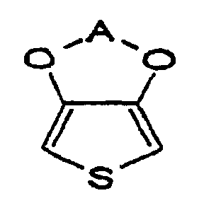
- Procédé selon la revendication 29, dans lequel la seconde couche conductrice est formée par polymérisation chimique.
- Procédé selon la revendication 30, dans lequel la polymérisation chimique comprend l'immersion de l'électrode portant le film diélectrique dans une solution de monomère comprenant le dérivé de thiophène et un agent tensio-actif anionique, et l'immersion supplémentaire de l'électrode ainsi immergée dans une solution oxydante comprenant un sulfate, formant, par cet effet, un polymère conducteur du dérivé de thiophène sur ledit film diélectrique.
- Procédé selon la revendication 31, dans lequel le sulfate est du sulfate ferrique.
- Procédé selon la revendication 31 ou 32 dans lequel l'agent tensio-actif anionique comprend un anion sulfonate.
- Procédé selon la revendication 31, 32 ou 33, dans lequel la solution de monomère comprend,en outre, un composé phénolique.
- Procédé selon la revendication 34, dans lequel le composé phénolique est phénol, nitrophénol, cyanophénol, acide hydroxybenzoïque, hydroxyphénol ou acétophénol ou l'un de leurs mélanges.
- Procédé selon la revendication 30, dans lequel la polymérisation chimique comprend l'immersion de l'électrode portant le film diélectrique dans un système de polymérisation comprenant le dérivé de thiophène, un agent tensio-actif anionique capable de donner un anion monovalent, et un oxydant capable de donner l'anion polyvalent jusqu'à ce que le polymère conducteur résultant du dérivé de thiophène soit formé dans une épaisseur donnée.
- Procédé selon la revendication 29, dans lequel la seconde couche de polymère conductrice est formée par immersion dans une solution d'un polymère conducteur du dérivé de thiophène.
- Procédé selon l'une quelconque des revendications 29 à 37, comprenant, en outre, la formation d'une troisième couche de polymère conductrice sur la première couche conductrice sur un côté opposé au côté où ladite seconde couche conductrice a été formée, la troisième couche de polymère conductrice comprenant un polymère d'un dérivé de thiophène de formuledans laquelle A représente un groupe alkylène non substitué ou substitué.

- Procédé selon la revendication 38, dans lequel la troisième couche de polymère conductrice est formée par polymérisation chimique par immersion dans une solution de polymère conductrice comme définie dans l'une quelconque des revendications 30 à 37.
- Procédé selon l'une quelconque des revendications 15 ou 23 à 39, dans lequel la première couche de polymère conductrice est formée par polymérisation électrolytique.
- Procédé selon la revendication 40, dans lequel la polymérisation électrolytique est conduite dans un milieu aqueux.
- Procédé selon la revendication 41, dans lequel la polymérisation électrolytique est conduite dans une solution aqueuse de pyrrole ou de l'un de ses dérivés comprenant un composé phénolique.
- Procédé selon la revendication 42, dans lequel le composé phénolique est phénol, nitrophénol, cyanophénol, acide hydroxybenzoïque, hydroxyphénol ou acétophénol ou l'un de leurs mélanges.
Applications Claiming Priority (6)
| Application Number | Priority Date | Filing Date | Title |
|---|---|---|---|
| JP08232096A JP3223790B2 (ja) | 1995-06-26 | 1996-04-04 | コンデンサ及びその製造方法 |
| JP8232096 | 1996-04-04 | ||
| JP82320/96 | 1996-04-04 | ||
| JP24439796 | 1996-09-17 | ||
| JP24439796A JP3520688B2 (ja) | 1996-09-17 | 1996-09-17 | コンデンサ及びその製造方法 |
| JP244397/96 | 1996-09-17 |
Publications (3)
| Publication Number | Publication Date |
|---|---|
| EP0803886A2 EP0803886A2 (fr) | 1997-10-29 |
| EP0803886A3 EP0803886A3 (fr) | 1999-03-24 |
| EP0803886B1 true EP0803886B1 (fr) | 2003-06-18 |
Family
ID=26423343
Family Applications (1)
| Application Number | Title | Priority Date | Filing Date |
|---|---|---|---|
| EP97302334A Expired - Lifetime EP0803886B1 (fr) | 1996-04-04 | 1997-04-04 | Condensateurs à électrolyte solide comprenant une couche conductrice d'une polymère de pyrrole ou son dérivé, et son procédé de fabrication |
Country Status (3)
| Country | Link |
|---|---|
| US (2) | US5812367A (fr) |
| EP (1) | EP0803886B1 (fr) |
| DE (1) | DE69722849T2 (fr) |
Families Citing this family (207)
| Publication number | Priority date | Publication date | Assignee | Title |
|---|---|---|---|---|
| DE69833149T2 (de) * | 1997-06-20 | 2006-09-07 | Matsushita Electric Industrial Co., Ltd., Kadoma | Elektrolytkondensator und dessen Herstellungsverfahren |
| JP3157748B2 (ja) | 1997-07-30 | 2001-04-16 | 富山日本電気株式会社 | 導電性高分子を用いた固体電解コンデンサ及びその製造方法 |
| JP3228323B2 (ja) * | 1997-09-10 | 2001-11-12 | 日本電気株式会社 | 固体電解コンデンサおよびその製造方法 |
| JP3065286B2 (ja) * | 1997-09-24 | 2000-07-17 | 日本電気株式会社 | 固体電解コンデンサおよびその製造方法 |
| US6168639B1 (en) * | 1997-10-09 | 2001-01-02 | Sanyo Electric Co., Ltd. | Solid electrolyte capacitor, and process and apparatus for producing same |
| CA2278643C (fr) * | 1997-11-28 | 2012-02-07 | Showa Denko K.K. | Condensateur electrolytique solide et son procede de fabrication |
| ES2219788T3 (es) * | 1997-12-31 | 2004-12-01 | Societe D'applications Electroniques Pour La Physique, La Science Et L'industrie | Captador capacitativo de la medicion de la humedad y procedimiento de fabricacion de estos captadores. |
| DE69939262D1 (de) * | 1998-06-25 | 2008-09-18 | Nichicon Corp | Verfahren zur herstellung eines festelektrolytkondensators |
| AU4397499A (en) * | 1998-07-06 | 2000-01-24 | Showa Denko Kabushiki Kaisha | Conductive polymer, solid electrolytic capacitor, and processes for producing these |
| JP3667531B2 (ja) * | 1998-07-07 | 2005-07-06 | 松下電器産業株式会社 | 電解コンデンサの製造方法 |
| EP1003179B1 (fr) * | 1998-11-17 | 2004-08-25 | Agfa-Gevaert | Procédé de préparation d'une couche de polythiophène conductif à basse température |
| US6333145B1 (en) | 1998-11-17 | 2001-12-25 | Agfa-Gevaert | Method for preparing a conductive polythiophene layer at low temperature |
| JP3245567B2 (ja) * | 1999-01-25 | 2002-01-15 | 富山日本電気株式会社 | 固体電解コンデンサの製造方法 |
| JP2001044080A (ja) * | 1999-07-30 | 2001-02-16 | Nec Corp | 固体電解コンデンサおよびその製造方法 |
| WO2001020625A1 (fr) * | 1999-09-10 | 2001-03-22 | Matsushita Electric Industrial Co., Ltd. | Condensateur electrolytique solide, procede de production de celui-ci et solution d'agent oxydant de polymerisation de polymere conducteur |
| US6602741B1 (en) * | 1999-09-14 | 2003-08-05 | Matsushita Electric Industrial Co., Ltd. | Conductive composition precursor, conductive composition, solid electrolytic capacitor, and their manufacturing method |
| US6552896B1 (en) * | 1999-10-28 | 2003-04-22 | Matsushita Electric Industrial Co., Ltd. | Solid electrolytic capacitor and method for manufacturing the same |
| US6631074B2 (en) | 2000-05-12 | 2003-10-07 | Maxwell Technologies, Inc. | Electrochemical double layer capacitor having carbon powder electrodes |
| US6627252B1 (en) | 2000-05-12 | 2003-09-30 | Maxwell Electronic Components, Inc. | Electrochemical double layer capacitor having carbon powder electrodes |
| US6334966B1 (en) * | 2000-11-06 | 2002-01-01 | Kemet Electronics Corporation | Chemical oxidative preparation of conductive polymers |
| US7110244B2 (en) * | 2001-04-12 | 2006-09-19 | Showa Denko K.K. | Production process for niobium capacitor |
| US6674635B1 (en) | 2001-06-11 | 2004-01-06 | Avx Corporation | Protective coating for electrolytic capacitors |
| US6459565B1 (en) * | 2001-06-11 | 2002-10-01 | Kemet Electronics Corporation | Surface mount aluminum capacitor having anode foil anodized in an aqueous phosphate solution |
| AU2002322323A1 (en) * | 2001-06-25 | 2003-01-08 | Massachusetts Institute Of Technology | Bioerodible conducting materials |
| US6731497B2 (en) * | 2001-07-11 | 2004-05-04 | Tdk Corporation | Solid electrolytic capacitor and method for manufacturing the same |
| US6643119B2 (en) | 2001-11-02 | 2003-11-04 | Maxwell Technologies, Inc. | Electrochemical double layer capacitor having carbon powder electrodes |
| US6813139B2 (en) * | 2001-11-02 | 2004-11-02 | Maxwell Technologies, Inc. | Electrochemical double layer capacitor having carbon powder electrodes |
| US6864147B1 (en) | 2002-06-11 | 2005-03-08 | Avx Corporation | Protective coating for electrolytic capacitors |
| WO2003107366A1 (fr) * | 2002-06-18 | 2003-12-24 | ティーディーケイ株式会社 | Condensateur electrolytique solide et procede de fabrication correspondant |
| JP4366055B2 (ja) * | 2002-08-01 | 2009-11-18 | ローム株式会社 | 固体電解コンデンサの製造方法 |
| US7056600B2 (en) * | 2002-08-23 | 2006-06-06 | Agfa Gevaert | Layer configuration comprising an electron-blocking element |
| US7307276B2 (en) * | 2002-08-23 | 2007-12-11 | Agfa-Gevaert | Layer configuration comprising an electron-blocking element |
| AU2003262547A1 (en) * | 2002-08-23 | 2004-03-11 | Agfa-Gevaert | Layer configuration comprising an electron-blocking element |
| AU2003262545A1 (en) * | 2002-08-23 | 2004-03-11 | Agfa-Gevaert | Layer configuration comprising an electron-blocking element |
| US6977390B2 (en) * | 2002-08-23 | 2005-12-20 | Agfa Gevaert | Layer configuration comprising an electron-blocking element |
| US20040240152A1 (en) * | 2003-05-30 | 2004-12-02 | Schott Joachim Hossick | Capacitor and method for producing a capacitor |
| DE60327869D1 (de) * | 2002-09-30 | 2009-07-16 | Nippon Chemicon | Festelektrolytkondensator |
| US7079377B2 (en) * | 2002-09-30 | 2006-07-18 | Joachim Hossick Schott | Capacitor and method for producing a capacitor |
| US6965509B2 (en) * | 2002-12-02 | 2005-11-15 | The United States Of America As Represented By The Secretary Of The Navy | Poly (3,4-alkylenedioxythiophene)-based capacitors using ionic liquids as supporting electrolytes |
| EP1592030B1 (fr) * | 2003-01-31 | 2012-01-11 | Showa Denko K.K. | Procede de fabrication d'un condensateur electrolytique solide |
| JP4381009B2 (ja) * | 2003-03-12 | 2009-12-09 | 新光電気工業株式会社 | パターン描画装置、パターン描画方法、および検査装置 |
| US7791860B2 (en) | 2003-07-09 | 2010-09-07 | Maxwell Technologies, Inc. | Particle based electrodes and methods of making same |
| US7352558B2 (en) | 2003-07-09 | 2008-04-01 | Maxwell Technologies, Inc. | Dry particle based capacitor and methods of making same |
| US7920371B2 (en) | 2003-09-12 | 2011-04-05 | Maxwell Technologies, Inc. | Electrical energy storage devices with separator between electrodes and methods for fabricating the devices |
| JP4632651B2 (ja) * | 2003-10-08 | 2011-02-16 | 三洋電機株式会社 | 固体電解コンデンサ |
| US7582707B2 (en) * | 2004-01-12 | 2009-09-01 | Air Products And Chemicals, Inc. | Aqueous blends and films comprising a first electrically conducting conjugated polymer and a second electrically conducting conjugated polymer |
| DE102004006583A1 (de) * | 2004-02-10 | 2005-09-01 | H.C. Starck Gmbh | Polythiophenformulierungen zur Verbesserung von organischen Leuchtdioden |
| US7090946B2 (en) | 2004-02-19 | 2006-08-15 | Maxwell Technologies, Inc. | Composite electrode and method for fabricating same |
| DE102004022110A1 (de) * | 2004-05-05 | 2005-12-01 | H.C. Starck Gmbh | Verfahren zur Herstellung von Elektrolytkondensatoren |
| WO2006022625A2 (fr) * | 2004-07-22 | 2006-03-02 | Precision Dynamics Corporation | Element de stockage de charge rectificateur ameliore |
| US7440258B2 (en) | 2005-03-14 | 2008-10-21 | Maxwell Technologies, Inc. | Thermal interconnects for coupling energy storage devices |
| JPWO2006115110A1 (ja) * | 2005-04-20 | 2008-12-18 | 松下電器産業株式会社 | 固体電解コンデンサの検査装置と検査方法 |
| US7099143B1 (en) | 2005-05-24 | 2006-08-29 | Avx Corporation | Wet electrolytic capacitors |
| US7453144B2 (en) * | 2005-06-29 | 2008-11-18 | Intel Corporation | Thin film capacitors and methods of making the same |
| WO2007004555A1 (fr) * | 2005-06-30 | 2007-01-11 | Showa Denko K. K. | Élément de condensateur à électrolyte solide et son procédé de production |
| DE102005033839A1 (de) * | 2005-07-20 | 2007-01-25 | H.C. Starck Gmbh | Elektrolytkondensatoren mit polymerer Außenschicht und Verfahren zur ihrer Herstellung |
| JP2009505412A (ja) | 2005-08-19 | 2009-02-05 | エイブイエックス リミテッド | ポリマーベースの固体コンデンサおよびその製造方法 |
| GB0517952D0 (en) * | 2005-09-02 | 2005-10-12 | Avx Ltd | Method of forming anode bodies for solid state capacitors |
| DE102005043828A1 (de) | 2005-09-13 | 2007-03-22 | H.C. Starck Gmbh | Verfahren zur Herstellung von Elektrolytkondensatoren |
| US8257463B2 (en) * | 2006-01-23 | 2012-09-04 | Avx Corporation | Capacitor anode formed from flake powder |
| US7480130B2 (en) | 2006-03-09 | 2009-01-20 | Avx Corporation | Wet electrolytic capacitor |
| US7511943B2 (en) | 2006-03-09 | 2009-03-31 | Avx Corporation | Wet electrolytic capacitor containing a cathode coating |
| JP4804336B2 (ja) * | 2006-12-27 | 2011-11-02 | 三洋電機株式会社 | 固体電解コンデンサ |
| US20080232032A1 (en) | 2007-03-20 | 2008-09-25 | Avx Corporation | Anode for use in electrolytic capacitors |
| US7649730B2 (en) | 2007-03-20 | 2010-01-19 | Avx Corporation | Wet electrolytic capacitor containing a plurality of thin powder-formed anodes |
| US7554792B2 (en) | 2007-03-20 | 2009-06-30 | Avx Corporation | Cathode coating for a wet electrolytic capacitor |
| US7460356B2 (en) | 2007-03-20 | 2008-12-02 | Avx Corporation | Neutral electrolyte for a wet electrolytic capacitor |
| US7483259B2 (en) | 2007-03-21 | 2009-01-27 | Avx Corporation | Solid electrolytic capacitor containing a barrier layer |
| US7515396B2 (en) | 2007-03-21 | 2009-04-07 | Avx Corporation | Solid electrolytic capacitor containing a conductive polymer |
| US7460358B2 (en) | 2007-03-21 | 2008-12-02 | Avx Corporation | Solid electrolytic capacitor containing a protective adhesive layer |
| CN101689428B (zh) | 2007-07-02 | 2012-05-30 | 三洋电机株式会社 | 固体电解电容器 |
| US7760487B2 (en) | 2007-10-22 | 2010-07-20 | Avx Corporation | Doped ceramic powder for use in forming capacitor anodes |
| US7760488B2 (en) | 2008-01-22 | 2010-07-20 | Avx Corporation | Sintered anode pellet treated with a surfactant for use in an electrolytic capacitor |
| US7852615B2 (en) | 2008-01-22 | 2010-12-14 | Avx Corporation | Electrolytic capacitor anode treated with an organometallic compound |
| US7768773B2 (en) * | 2008-01-22 | 2010-08-03 | Avx Corporation | Sintered anode pellet etched with an organic acid for use in an electrolytic capacitor |
| US7826200B2 (en) * | 2008-03-25 | 2010-11-02 | Avx Corporation | Electrolytic capacitor assembly containing a resettable fuse |
| US8094434B2 (en) * | 2008-04-01 | 2012-01-10 | Avx Corporation | Hermetically sealed capacitor assembly |
| US8199462B2 (en) | 2008-09-08 | 2012-06-12 | Avx Corporation | Solid electrolytic capacitor for embedding into a circuit board |
| KR101501743B1 (ko) * | 2008-09-09 | 2015-03-11 | 가부시키가이샤 엔디씨 | 장갑 및 그 부속품 |
| US8023250B2 (en) * | 2008-09-12 | 2011-09-20 | Avx Corporation | Substrate for use in wet capacitors |
| US20100085685A1 (en) | 2008-10-06 | 2010-04-08 | Avx Corporation | Capacitor Anode Formed From a Powder Containing Coarse Agglomerates and Fine Agglomerates |
| US8279585B2 (en) | 2008-12-09 | 2012-10-02 | Avx Corporation | Cathode for use in a wet capacitor |
| US8203827B2 (en) | 2009-02-20 | 2012-06-19 | Avx Corporation | Anode for a solid electrolytic capacitor containing a non-metallic surface treatment |
| US8223473B2 (en) | 2009-03-23 | 2012-07-17 | Avx Corporation | Electrolytic capacitor containing a liquid electrolyte |
| GB2468942B (en) | 2009-03-23 | 2014-02-19 | Avx Corp | High voltage electrolytic capacitors |
| US8405956B2 (en) * | 2009-06-01 | 2013-03-26 | Avx Corporation | High voltage electrolytic capacitors |
| US8441777B2 (en) | 2009-05-29 | 2013-05-14 | Avx Corporation | Solid electrolytic capacitor with facedown terminations |
| US8279583B2 (en) | 2009-05-29 | 2012-10-02 | Avx Corporation | Anode for an electrolytic capacitor that contains individual components connected by a refractory metal paste |
| US8199461B2 (en) | 2009-05-29 | 2012-06-12 | Avx Corporation | Refractory metal paste for solid electrolytic capacitors |
| US8139344B2 (en) | 2009-09-10 | 2012-03-20 | Avx Corporation | Electrolytic capacitor assembly and method with recessed leadframe channel |
| US8194395B2 (en) | 2009-10-08 | 2012-06-05 | Avx Corporation | Hermetically sealed capacitor assembly |
| US8125768B2 (en) | 2009-10-23 | 2012-02-28 | Avx Corporation | External coating for a solid electrolytic capacitor |
| CN102396040B (zh) * | 2009-12-18 | 2013-01-16 | 帝化株式会社 | 固体电解电容器 |
| US8339771B2 (en) * | 2010-02-19 | 2012-12-25 | Avx Corporation | Conductive adhesive for use in a solid electrolytic capacitor |
| US8125769B2 (en) | 2010-07-22 | 2012-02-28 | Avx Corporation | Solid electrolytic capacitor assembly with multiple cathode terminations |
| US8259436B2 (en) | 2010-08-03 | 2012-09-04 | Avx Corporation | Mechanically robust solid electrolytic capacitor assembly |
| US8279584B2 (en) | 2010-08-12 | 2012-10-02 | Avx Corporation | Solid electrolytic capacitor assembly |
| US8605411B2 (en) | 2010-09-16 | 2013-12-10 | Avx Corporation | Abrasive blasted conductive polymer cathode for use in a wet electrolytic capacitor |
| US8199460B2 (en) | 2010-09-27 | 2012-06-12 | Avx Corporation | Solid electrolytic capacitor with improved anode termination |
| US8514547B2 (en) | 2010-11-01 | 2013-08-20 | Avx Corporation | Volumetrically efficient wet electrolytic capacitor |
| US8259435B2 (en) | 2010-11-01 | 2012-09-04 | Avx Corporation | Hermetically sealed wet electrolytic capacitor |
| US8824122B2 (en) | 2010-11-01 | 2014-09-02 | Avx Corporation | Solid electrolytic capacitor for use in high voltage and high temperature applications |
| US8848342B2 (en) | 2010-11-29 | 2014-09-30 | Avx Corporation | Multi-layered conductive polymer coatings for use in high voltage solid electrolytic capacitors |
| US8576543B2 (en) | 2010-12-14 | 2013-11-05 | Avx Corporation | Solid electrolytic capacitor containing a poly(3,4-ethylenedioxythiophene) quaternary onium salt |
| US8493713B2 (en) | 2010-12-14 | 2013-07-23 | Avx Corporation | Conductive coating for use in electrolytic capacitors |
| US8477479B2 (en) | 2011-01-12 | 2013-07-02 | Avx Corporation | Leadwire configuration for a planar anode of a wet electrolytic capacitor |
| US8582278B2 (en) | 2011-03-11 | 2013-11-12 | Avx Corporation | Solid electrolytic capacitor with improved mechanical stability |
| US8451588B2 (en) | 2011-03-11 | 2013-05-28 | Avx Corporation | Solid electrolytic capacitor containing a conductive coating formed from a colloidal dispersion |
| US8514550B2 (en) | 2011-03-11 | 2013-08-20 | Avx Corporation | Solid electrolytic capacitor containing a cathode termination with a slot for an adhesive |
| US8300387B1 (en) | 2011-04-07 | 2012-10-30 | Avx Corporation | Hermetically sealed electrolytic capacitor with enhanced mechanical stability |
| US9767964B2 (en) | 2011-04-07 | 2017-09-19 | Avx Corporation | Multi-anode solid electrolytic capacitor assembly |
| US8947857B2 (en) | 2011-04-07 | 2015-02-03 | Avx Corporation | Manganese oxide capacitor for use in extreme environments |
| US8379372B2 (en) | 2011-04-07 | 2013-02-19 | Avx Corporation | Housing configuration for a solid electrolytic capacitor |
| US8422200B2 (en) * | 2011-05-25 | 2013-04-16 | Inpaq Technology Co., Ltd. | Conductive structure having an embedded electrode, and solid capacitor having an embedded electrode and method of making the same |
| US8451586B2 (en) | 2011-09-13 | 2013-05-28 | Avx Corporation | Sealing assembly for a wet electrolytic capacitor |
| US9105401B2 (en) | 2011-12-02 | 2015-08-11 | Avx Corporation | Wet electrolytic capacitor containing a gelled working electrolyte |
| US9275799B2 (en) | 2011-12-20 | 2016-03-01 | Avx Corporation | Wet electrolytic capacitor containing an improved anode |
| US10643796B2 (en) * | 2012-02-27 | 2020-05-05 | Kemet Electronics Corporation | Conductive polymer dispersion with enhanced coverage |
| DE102013101443B4 (de) | 2012-03-01 | 2025-05-28 | KYOCERA AVX Components Corporation (n. d. Ges. d. Staates Delaware) | Verfahren zum Ausbilden eines Ultrahochspannungs-Festelektrolytkondensators |
| US8971019B2 (en) | 2012-03-16 | 2015-03-03 | Avx Corporation | Wet capacitor cathode containing an alkyl-substituted poly(3,4-ethylenedioxythiophene) |
| JP2013219362A (ja) | 2012-04-11 | 2013-10-24 | Avx Corp | 過酷な条件下で強化された機械的安定性を有する固体電解コンデンサ |
| US8947858B2 (en) | 2012-04-24 | 2015-02-03 | Avx Corporation | Crimped leadwire for improved contact with anodes of a solid electrolytic capacitor |
| US8760852B2 (en) | 2012-04-24 | 2014-06-24 | Avx Corporation | Solid electrolytic capacitor containing multiple sinter bonded anode leadwires |
| GB2502703B (en) | 2012-05-30 | 2016-09-21 | Avx Corp | Notched lead for a solid electrolytic capacitor |
| US9776281B2 (en) | 2012-05-30 | 2017-10-03 | Avx Corporation | Notched lead wire for a solid electrolytic capacitor |
| CN103578768B (zh) | 2012-07-19 | 2017-10-31 | Avx公司 | 用在电解电容器固体电解质中的非离子表面活性剂 |
| DE102013213720A1 (de) | 2012-07-19 | 2014-01-23 | Avx Corporation | Temperaturstabiler Festelektrolytkondensator |
| US9362057B2 (en) | 2012-07-26 | 2016-06-07 | Industrial Technology Research Institute | Electrolyte mixture for electrolytic capacitor, composition for conductive polymer synthesis and conductive polymer solid electrolytic capacitor formed by using the same |
| JP5933397B2 (ja) | 2012-08-30 | 2016-06-08 | エイヴィーエックス コーポレイション | 固体電解コンデンサの製造方法および固体電解コンデンサ |
| GB2512480B (en) | 2013-03-13 | 2018-05-30 | Avx Corp | Solid electrolytic capacitor for use in extreme conditions |
| GB2512486B (en) | 2013-03-15 | 2018-07-18 | Avx Corp | Wet electrolytic capacitor |
| US9324503B2 (en) | 2013-03-15 | 2016-04-26 | Avx Corporation | Solid electrolytic capacitor |
| GB2512481B (en) | 2013-03-15 | 2018-05-30 | Avx Corp | Wet electrolytic capacitor for use at high temperatures |
| US9240285B2 (en) | 2013-04-29 | 2016-01-19 | Avx Corporation | Multi-notched anode for electrolytic capacitor |
| GB2516529B (en) | 2013-05-13 | 2018-08-29 | Avx Corp | Solid electrolytic capacitor containing a multi-layered adhesion coating |
| GB2517019B (en) | 2013-05-13 | 2018-08-29 | Avx Corp | Solid electrolytic capacitor containing conductive polymer particles |
| GB2514486B (en) | 2013-05-13 | 2018-08-29 | Avx Corp | Solid electrolytic capacitor containing a pre-coat layer |
| US9236192B2 (en) | 2013-08-15 | 2016-01-12 | Avx Corporation | Moisture resistant solid electrolytic capacitor assembly |
| US9269499B2 (en) | 2013-08-22 | 2016-02-23 | Avx Corporation | Thin wire/thick wire lead assembly for electrolytic capacitor |
| US9165718B2 (en) | 2013-09-16 | 2015-10-20 | Avx Corporation | Wet electrolytic capacitor containing a hydrogen protection layer |
| US9183991B2 (en) | 2013-09-16 | 2015-11-10 | Avx Corporation | Electro-polymerized coating for a wet electrolytic capacitor |
| US10403444B2 (en) | 2013-09-16 | 2019-09-03 | Avx Corporation | Wet electrolytic capacitor containing a composite coating |
| US9236193B2 (en) | 2013-10-02 | 2016-01-12 | Avx Corporation | Solid electrolytic capacitor for use under high temperature and humidity conditions |
| WO2015069247A1 (fr) * | 2013-11-07 | 2015-05-14 | Hewlett Packard Development Company, L.P. | Couche composite, couche métallique et couche anodisée |
| US9589733B2 (en) | 2013-12-17 | 2017-03-07 | Avx Corporation | Stable solid electrolytic capacitor containing a nanocomposite |
| US9916935B2 (en) | 2014-11-07 | 2018-03-13 | Avx Corporation | Solid electrolytic capacitor with increased volumetric efficiency |
| US9620293B2 (en) | 2014-11-17 | 2017-04-11 | Avx Corporation | Hermetically sealed capacitor for an implantable medical device |
| US9892860B2 (en) | 2014-11-24 | 2018-02-13 | Avx Corporation | Capacitor with coined lead frame |
| US9837216B2 (en) | 2014-12-18 | 2017-12-05 | Avx Corporation | Carrier wire for solid electrolytic capacitors |
| US9620294B2 (en) | 2014-12-30 | 2017-04-11 | Avx Corporation | Wet electrolytic capacitor containing a recessed planar anode and a restraint |
| US10014108B2 (en) | 2015-03-13 | 2018-07-03 | Avx Corporation | Low profile multi-anode assembly |
| US9754730B2 (en) | 2015-03-13 | 2017-09-05 | Avx Corporation | Low profile multi-anode assembly in cylindrical housing |
| US10297393B2 (en) | 2015-03-13 | 2019-05-21 | Avx Corporation | Ultrahigh voltage capacitor assembly |
| US9928963B2 (en) | 2015-03-13 | 2018-03-27 | Avx Corporation | Thermally conductive encapsulant material for a capacitor assembly |
| US10074487B2 (en) | 2015-05-18 | 2018-09-11 | Avx Corporation | Solid electrolytic capacitor having a high capacitance |
| US9905368B2 (en) | 2015-08-04 | 2018-02-27 | Avx Corporation | Multiple leadwires using carrier wire for low ESR electrolytic capacitors |
| US9842704B2 (en) | 2015-08-04 | 2017-12-12 | Avx Corporation | Low ESR anode lead tape for a solid electrolytic capacitor |
| US10886516B2 (en) | 2015-09-15 | 2021-01-05 | Ohio State Innovation Foundation | Active membrane with controlled ion-transport |
| US10186382B2 (en) | 2016-01-18 | 2019-01-22 | Avx Corporation | Solid electrolytic capacitor with improved leakage current |
| US9545008B1 (en) | 2016-03-24 | 2017-01-10 | Avx Corporation | Solid electrolytic capacitor for embedding into a circuit board |
| US9907176B2 (en) | 2016-03-28 | 2018-02-27 | Avx Corporation | Solid electrolytic capacitor module with improved planarity |
| US10381165B2 (en) | 2016-05-20 | 2019-08-13 | Avx Corporation | Solid electrolytic capacitor for use at high temperatures |
| US9870869B1 (en) | 2016-06-28 | 2018-01-16 | Avx Corporation | Wet electrolytic capacitor |
| US9870868B1 (en) | 2016-06-28 | 2018-01-16 | Avx Corporation | Wet electrolytic capacitor for use in a subcutaneous implantable cardioverter-defibrillator |
| US10763046B2 (en) | 2016-09-15 | 2020-09-01 | Avx Corporation | Solid electrolytic capacitor with improved leakage current |
| JP7071345B2 (ja) | 2016-09-22 | 2022-05-18 | キョーセラ・エイブイエックス・コンポーネンツ・コーポレーション | 非紛争採鉱地から供給されるバルブメタルを含む電解キャパシタ及びそれを形成する方法 |
| EP3529816B1 (fr) | 2016-10-18 | 2026-05-06 | KYOCERA AVX Components Corporation | Condensateur électrolytique solide à performances améliorées à hautes températures et tensions |
| WO2018075330A2 (fr) | 2016-10-18 | 2018-04-26 | Avx Corporation | Condensateur électrolytique solide à courant de fuite amélioré |
| EP3529815B1 (fr) | 2016-10-18 | 2026-05-06 | KYOCERA AVX Components Corporation | Condensateur electrolytique solide comprenant un agent silane entre l'anode et le polymere conducteur |
| US10431389B2 (en) | 2016-11-14 | 2019-10-01 | Avx Corporation | Solid electrolytic capacitor for high voltage environments |
| US10832871B2 (en) | 2016-11-14 | 2020-11-10 | Avx Corporation | Wet electrolytic capacitor for an implantable medical device |
| US10643797B2 (en) | 2016-11-15 | 2020-05-05 | Avx Corporation | Casing material for a solid electrolytic capacitor |
| US10504657B2 (en) | 2016-11-15 | 2019-12-10 | Avx Corporation | Lead wire configuration for a solid electrolytic capacitor |
| US10475591B2 (en) | 2016-11-15 | 2019-11-12 | Avx Corporation | Solid electrolytic capacitor for use in a humid atmosphere |
| WO2018165065A1 (fr) | 2017-03-06 | 2018-09-13 | Avx Corporation | Ensemble condensateur à électrolyte solide |
| US10983011B2 (en) | 2017-05-08 | 2021-04-20 | Avx Corporation | Lifetime determining technique for a solid electrolytic capacitor and system for the same |
| WO2019005535A1 (fr) | 2017-06-29 | 2019-01-03 | Avx Corporation | Module contenant des condensateurs scellés hermétiquement |
| CN110720131B (zh) | 2017-07-03 | 2022-05-31 | 京瓷Avx元器件公司 | 固体电解质电容器组件 |
| EP3649661A4 (fr) | 2017-07-03 | 2021-03-31 | AVX Corporation | Condensateur électrolytique solide contenant un nanorevêtement |
| DE112018004392T5 (de) | 2017-09-21 | 2020-05-14 | Avx Corporation | Elektronisches bauteil, enthaltend eine metallkomponente, die aus einem konfliktfreien bergwerksstandort bezogen wurde, und ein verfahren zu dessen ausbildung |
| US11004615B2 (en) | 2017-12-05 | 2021-05-11 | Avx Corporation | Solid electrolytic capacitor for use at high temperatures |
| WO2019113055A1 (fr) | 2017-12-05 | 2019-06-13 | Avx Corporation | Condensateur électrolytique humide pour un dispositif médical implantable |
| CN109935727B (zh) * | 2017-12-15 | 2020-06-09 | 京东方科技集团股份有限公司 | 一种基板、显示装置及导电薄膜的制备方法 |
| US12476052B2 (en) | 2018-06-21 | 2025-11-18 | KYOCERA AVX Components Corporation | Delamination-resistant solid electrolytic capacitor |
| US11342129B2 (en) | 2018-06-21 | 2022-05-24 | KYOCERA AVX Components Corporation | Solid electrolytic capacitor with stable electrical properties at high temperatures |
| US12548715B2 (en) | 2018-06-21 | 2026-02-10 | KYOCERA AVX Components Corporation | Solid electrolytic capacitor containing an interfacial coating |
| WO2020033820A1 (fr) | 2018-08-10 | 2020-02-13 | Avx Corporation | Condensateur électrolytique solide formé à partir de particules polymères conductrices |
| EP3834217A4 (fr) | 2018-08-10 | 2022-05-11 | KYOCERA AVX Components Corporation | Condensateur électrolytique solide contenant un polymère intrinsèquement conducteur |
| US11081288B1 (en) | 2018-08-10 | 2021-08-03 | Avx Corporation | Solid electrolytic capacitor having a reduced anomalous charging characteristic |
| CN118280737A (zh) | 2018-08-10 | 2024-07-02 | 京瓷Avx元器件公司 | 包含聚苯胺的固体电解电容器 |
| US11380492B1 (en) | 2018-12-11 | 2022-07-05 | KYOCERA AVX Components Corporation | Solid electrolytic capacitor |
| US11955294B2 (en) | 2018-12-11 | 2024-04-09 | KYOCERA AVX Components Corporation | Solid electrolytic capacitor containing an intrinsically conductive polymer |
| CN110098060A (zh) * | 2019-04-17 | 2019-08-06 | 天津大学 | 一种降低pedot固体钽电容器漏电流的方法 |
| KR102700118B1 (ko) | 2019-04-25 | 2024-08-28 | 교세라 에이브이엑스 컴포넌츠 (방콕) 리미티드 | 고체 전해 콘덴서 |
| US11270847B1 (en) | 2019-05-17 | 2022-03-08 | KYOCERA AVX Components Corporation | Solid electrolytic capacitor with improved leakage current |
| DE112020002428T5 (de) | 2019-05-17 | 2022-01-27 | Avx Corporation | Festelektrolytkondensator |
| US11222755B2 (en) | 2019-05-17 | 2022-01-11 | KYOCERA AVX Components Corporation | Delamination-resistant solid electrolytic capacitor |
| WO2021055707A1 (fr) | 2019-09-18 | 2021-03-25 | Avx Corporation | Condensateur électrolytique solide destiné à être utilisé à des tensions élevées |
| US11404220B2 (en) | 2019-09-18 | 2022-08-02 | KYOCERA AVX Components Corporation | Solid electrolytic capacitor containing a barrier coating |
| DE112020006028T5 (de) | 2019-12-10 | 2022-10-06 | KYOCERA AVX Components Corporation | Festelektrolytkondensator, der eine Vorbeschichtung und ein intrinsisch leitfähiges Polymer enthält |
| US11756742B1 (en) | 2019-12-10 | 2023-09-12 | KYOCERA AVX Components Corporation | Tantalum capacitor with improved leakage current stability at high temperatures |
| WO2021119088A1 (fr) | 2019-12-10 | 2021-06-17 | Avx Corporation | Condensateur au tantale à stabilité accrue |
| US11763998B1 (en) | 2020-06-03 | 2023-09-19 | KYOCERA AVX Components Corporation | Solid electrolytic capacitor |
| US11631548B2 (en) | 2020-06-08 | 2023-04-18 | KYOCERA AVX Components Corporation | Solid electrolytic capacitor containing a moisture barrier |
| US11837415B2 (en) | 2021-01-15 | 2023-12-05 | KYOCERA AVX Components Corpration | Solid electrolytic capacitor |
| US12512274B2 (en) | 2022-08-26 | 2025-12-30 | KYOCERA AVX Components Corporation | Wet electrolytic capacitor containing a gelled working electrolyte |
| CN120809492B (zh) * | 2025-08-14 | 2026-02-06 | 韶关富仕达电子科技有限公司 | 一种耐高温的固态铝电解电容器及其制备方法 |
Family Cites Families (17)
| Publication number | Priority date | Publication date | Assignee | Title |
|---|---|---|---|---|
| US4697001A (en) * | 1984-09-04 | 1987-09-29 | Rockwell International Corporation | Chemical synthesis of conducting polypyrrole |
| US4697000A (en) * | 1984-09-04 | 1987-09-29 | Rockwell International Corporation | Process for producing polypyrrole powder and the material so produced |
| JPH0831400B2 (ja) * | 1986-12-23 | 1996-03-27 | 日本カ−リット株式会社 | 固体電解コンデンサ |
| US4780796A (en) * | 1987-01-13 | 1988-10-25 | The Japan Carlit Co., Ltd. | Solid electrolytic capacitor |
| JPS63173313A (ja) * | 1987-01-13 | 1988-07-16 | 日本カーリット株式会社 | 固体電解コンデンサ |
| JPH0722075B2 (ja) * | 1987-01-23 | 1995-03-08 | 日通工株式会社 | 固体電解コンデンサの半導体層形成方法 |
| JPH01253226A (ja) * | 1988-03-31 | 1989-10-09 | Matsushita Electric Ind Co Ltd | 固体電解コンデンサ及びその製造方法 |
| DE3814730A1 (de) * | 1988-04-30 | 1989-11-09 | Bayer Ag | Feststoff-elektrolyte und diese enthaltende elektrolyt-kondensatoren |
| US5071521A (en) * | 1989-09-06 | 1991-12-10 | Matsushita Electric Industrial Co., Ltd. | Method for manufacturing a solid electrolytic capacitor |
| US5119274A (en) * | 1989-12-29 | 1992-06-02 | Matsushita Electric Industrial Co., Ltd. | Solid capacitor |
| JPH0736375B2 (ja) * | 1991-04-05 | 1995-04-19 | 松下電器産業株式会社 | 固体電解コンデンサの製造方法 |
| EP0509451B1 (fr) * | 1991-04-15 | 1995-03-29 | Matsushita Electric Industrial Co., Ltd. | Condensateurs à électrolyte solide améliorés et leur procédé de fabrication |
| TW259806B (fr) * | 1992-09-16 | 1995-10-11 | Sekisui Plastics | |
| JPH07135126A (ja) * | 1993-11-10 | 1995-05-23 | Nec Corp | 固体電解コンデンサ及びその製造方法 |
| JP2937716B2 (ja) * | 1993-11-18 | 1999-08-23 | 日本電気株式会社 | タンタル固体電解コンデンサ及びその製造方法 |
| KR0162864B1 (ko) * | 1995-01-19 | 1999-01-15 | 김은영 | 가용 전기전도성 폴리피롤의 제조방법 |
| JP3068430B2 (ja) * | 1995-04-25 | 2000-07-24 | 富山日本電気株式会社 | 固体電解コンデンサ及びその製造方法 |
-
1997
- 1997-04-01 US US08/840,445 patent/US5812367A/en not_active Expired - Lifetime
- 1997-04-04 DE DE69722849T patent/DE69722849T2/de not_active Expired - Lifetime
- 1997-04-04 EP EP97302334A patent/EP0803886B1/fr not_active Expired - Lifetime
-
1998
- 1998-09-04 US US09/148,321 patent/US6206937B1/en not_active Expired - Fee Related
Also Published As
| Publication number | Publication date |
|---|---|
| DE69722849D1 (de) | 2003-07-24 |
| EP0803886A2 (fr) | 1997-10-29 |
| DE69722849T2 (de) | 2004-05-06 |
| US5812367A (en) | 1998-09-22 |
| US6206937B1 (en) | 2001-03-27 |
| EP0803886A3 (fr) | 1999-03-24 |
Similar Documents
| Publication | Publication Date | Title |
|---|---|---|
| EP0803886B1 (fr) | Condensateurs à électrolyte solide comprenant une couche conductrice d'une polymère de pyrrole ou son dérivé, et son procédé de fabrication | |
| US6793690B2 (en) | Conductive composition precursor, conductive composition, solid electrolytic capacitor, and their manufacturing method | |
| US5187649A (en) | Solid electrolytic capacitor and method for manufacturing the same | |
| US10325728B2 (en) | Electrolytic capacitor and production method for same | |
| JP3520688B2 (ja) | コンデンサ及びその製造方法 | |
| JP7734327B2 (ja) | 固体電解コンデンサ素子および固体電解コンデンサ | |
| JP7752360B2 (ja) | 固体電解コンデンサ素子および固体電解コンデンサ | |
| JP3515938B2 (ja) | 固体電解コンデンサおよびその製造方法 | |
| JP2001102255A (ja) | タンタル固体電解コンデンサおよびその製造方法 | |
| WO2022024771A1 (fr) | Élément condensateur à électrolyte solide et condensateur à électrolyte solide | |
| JPH05175082A (ja) | 固体電解コンデンサの製造方法 | |
| JPH1145824A (ja) | コンデンサ及びその製造方法 | |
| KR100365370B1 (ko) | 고체 전해 콘덴서의 제조방법 | |
| WO2022191050A1 (fr) | Condensateur électrolytique et son procédé de production | |
| JPH11312626A (ja) | コンデンサ及びその製造方法 | |
| JP3223790B2 (ja) | コンデンサ及びその製造方法 | |
| JP2002008946A (ja) | 固体電解コンデンサの製造方法 | |
| US10304634B2 (en) | Electrolytic capacitor | |
| JP3213700B2 (ja) | コンデンサの製造方法 | |
| JP2000106329A (ja) | コンデンサの製造方法 | |
| JP2783038B2 (ja) | コンデンサ | |
| JP2982543B2 (ja) | コンデンサの製造方法 | |
| JPH0521279A (ja) | コンデンサ及びその製造方法 | |
| JPH05234826A (ja) | コンデンサの製造方法 | |
| WO2007074869A1 (fr) | Condensateur a electrolyte solide et son procede de fabrication |
Legal Events
| Date | Code | Title | Description |
|---|---|---|---|
| PUAI | Public reference made under article 153(3) epc to a published international application that has entered the european phase |
Free format text: ORIGINAL CODE: 0009012 |
|
| 17P | Request for examination filed |
Effective date: 19970417 |
|
| AK | Designated contracting states |
Kind code of ref document: A2 Designated state(s): DE FR GB |
|
| PUAL | Search report despatched |
Free format text: ORIGINAL CODE: 0009013 |
|
| AK | Designated contracting states |
Kind code of ref document: A3 Designated state(s): DE FR GB |
|
| 17Q | First examination report despatched |
Effective date: 20010305 |
|
| GRAH | Despatch of communication of intention to grant a patent |
Free format text: ORIGINAL CODE: EPIDOS IGRA |
|
| GRAH | Despatch of communication of intention to grant a patent |
Free format text: ORIGINAL CODE: EPIDOS IGRA |
|
| GRAA | (expected) grant |
Free format text: ORIGINAL CODE: 0009210 |
|
| AK | Designated contracting states |
Designated state(s): DE FR GB |
|
| REG | Reference to a national code |
Ref country code: GB Ref legal event code: FG4D |
|
| REF | Corresponds to: |
Ref document number: 69722849 Country of ref document: DE Date of ref document: 20030724 Kind code of ref document: P |
|
| ET | Fr: translation filed | ||
| PLBE | No opposition filed within time limit |
Free format text: ORIGINAL CODE: 0009261 |
|
| STAA | Information on the status of an ep patent application or granted ep patent |
Free format text: STATUS: NO OPPOSITION FILED WITHIN TIME LIMIT |
|
| 26N | No opposition filed |
Effective date: 20040319 |
|
| PGFP | Annual fee paid to national office [announced via postgrant information from national office to epo] |
Ref country code: DE Payment date: 20120419 Year of fee payment: 16 |
|
| PGFP | Annual fee paid to national office [announced via postgrant information from national office to epo] |
Ref country code: GB Payment date: 20120404 Year of fee payment: 16 Ref country code: FR Payment date: 20120504 Year of fee payment: 16 |
|
| GBPC | Gb: european patent ceased through non-payment of renewal fee |
Effective date: 20130404 |
|
| PG25 | Lapsed in a contracting state [announced via postgrant information from national office to epo] |
Ref country code: DE Free format text: LAPSE BECAUSE OF NON-PAYMENT OF DUE FEES Effective date: 20131101 Ref country code: GB Free format text: LAPSE BECAUSE OF NON-PAYMENT OF DUE FEES Effective date: 20130404 |
|
| REG | Reference to a national code |
Ref country code: FR Ref legal event code: ST Effective date: 20131231 |
|
| REG | Reference to a national code |
Ref country code: DE Ref legal event code: R119 Ref document number: 69722849 Country of ref document: DE Effective date: 20131101 |
|
| PG25 | Lapsed in a contracting state [announced via postgrant information from national office to epo] |
Ref country code: FR Free format text: LAPSE BECAUSE OF NON-PAYMENT OF DUE FEES Effective date: 20130430 |